Week 2 Challenge : Surface meshing on a Pressure valve
AIM: To check the geometrical errors in the given 3D model and perform topology cleanup. And mesh the 3D model with given three different target lengths and compare the results.
PROCEDURE:
to perform goemtry checks
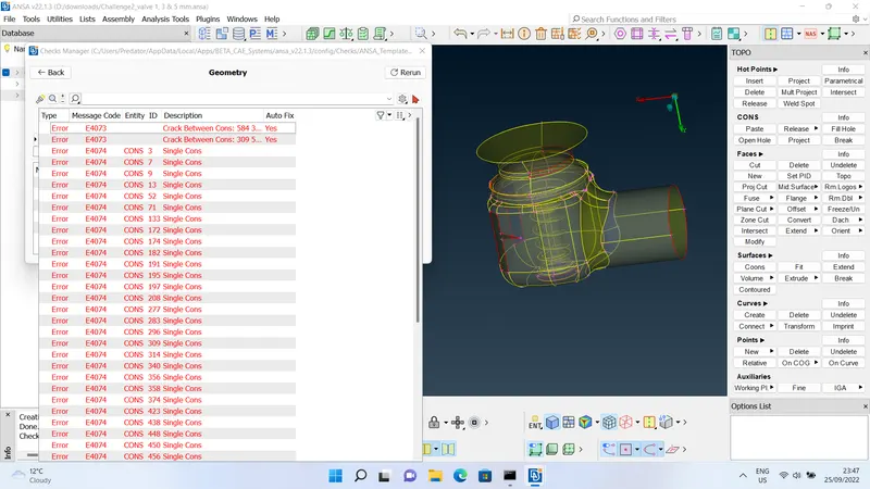
- to check the geometrical errors select the drop down menu from the tools tab>>checks>>geometry. Tick the boxes for triple cons and single cons, then press execute command to perform the checks.
- if there is any errors in model, they will be shown on the prompt window and selection can also be made through that window. as shown in the below picture
topology cleanup:
- to eliminate all the errors shown above, we need to define new surfaces at the location of single cons in order to make them as double cons.
- to define a surface, enable topo mode>> select new from the faces column>>it prompts a small window consists of four options(exsiting surface, planar, fitted and coons)>> select an appropriate option based on the location to define a new surface.
- i will be showing applications for each of the following:
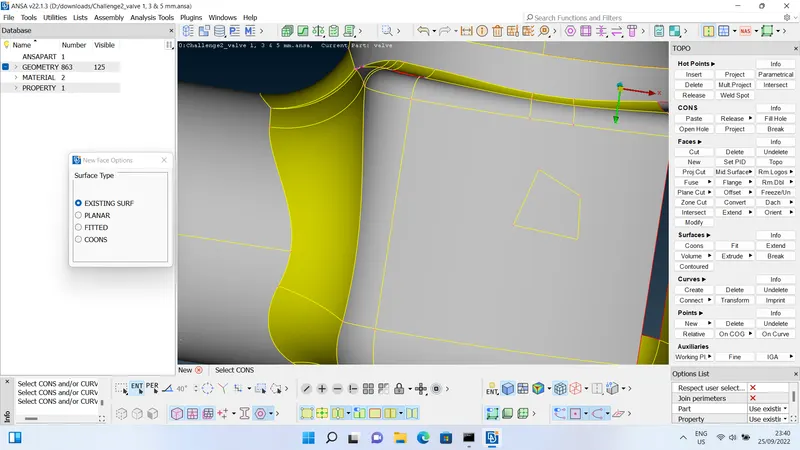
- existing surface: there is a trapezoidal cut on a surface of the valve as shown in the figure below, as it is a cut on a surface select the existing surface option.
 .
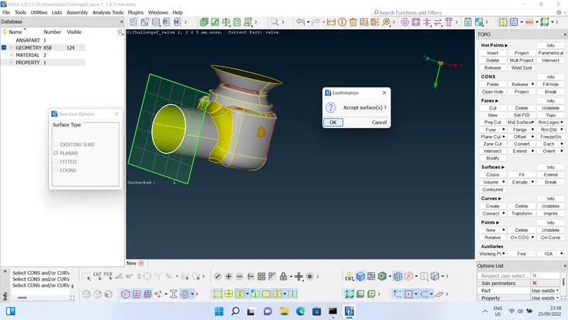
. - planar: this type can used to define a surface on a linear plane, this cannot be used to generate curved surfaces. this generates as shown below
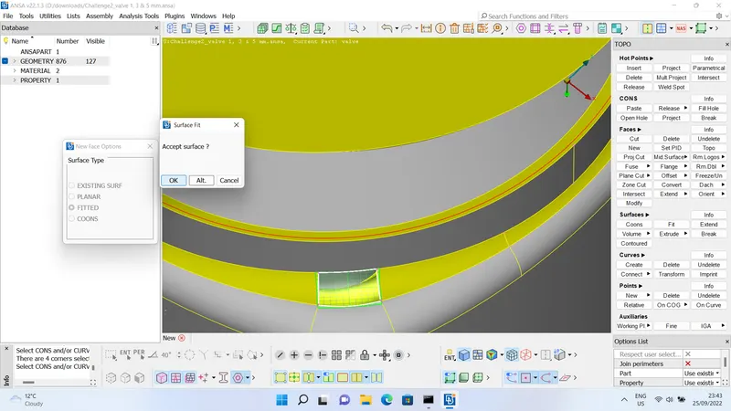
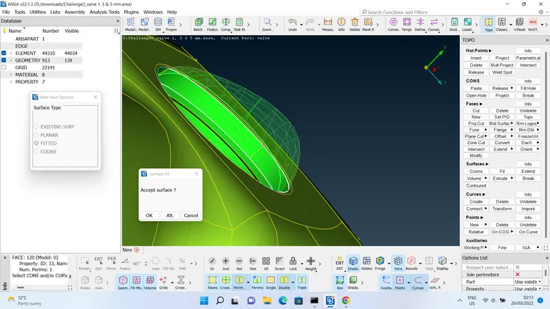
- fitted: this command can be used to create patching surfaces for small holes and irregular shapes also. as shown below
 .
. - coons: this options helps to define surfaces from edge to edge of the selection and regularly known shapes. as shown below
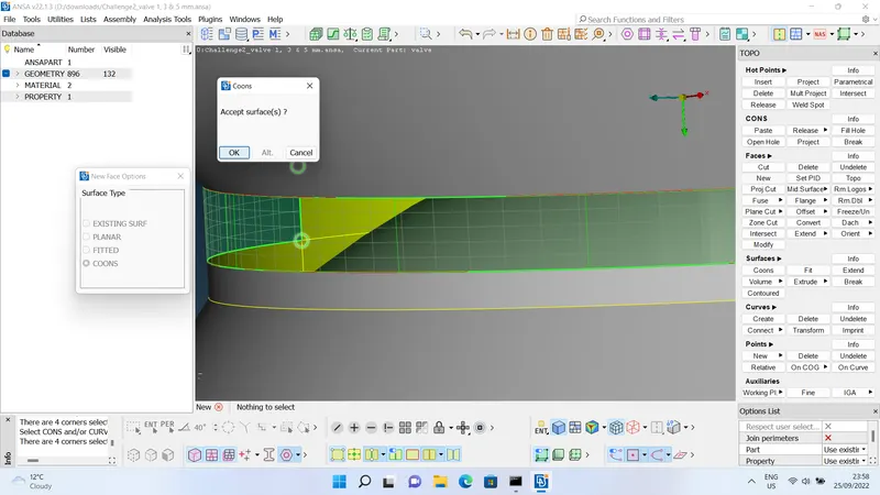
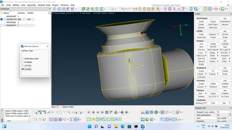
- usage of coons for an irregular shapes and fitted for an boundary less shapes doesn't define desirable surfaces. as shown below
 .
. - PID creation and allocation to different parts of the model:
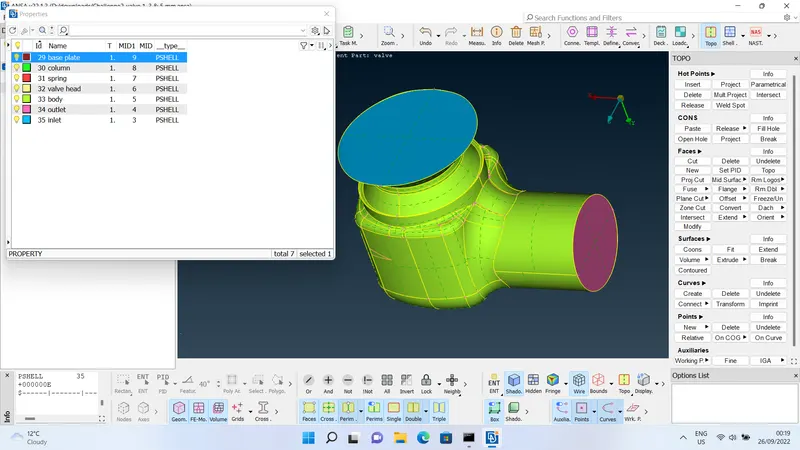
- PID is a Property ID which adds colour to selected entity, so that selection and isolation of the entities can be made fast and easy.
- PID can created and applied from properties list, colours for the PID can be edited with the help of colour pallette of dedicated PID.
- i have allocated PID for all the parts of the 3d model as shown
 .
.
Meshing:
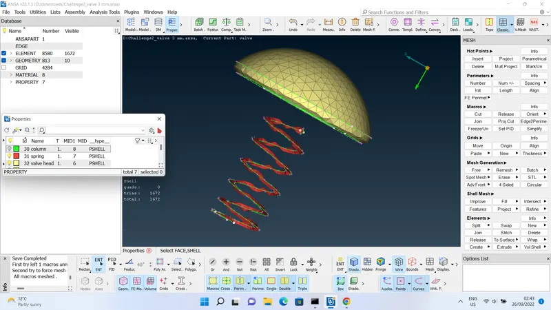
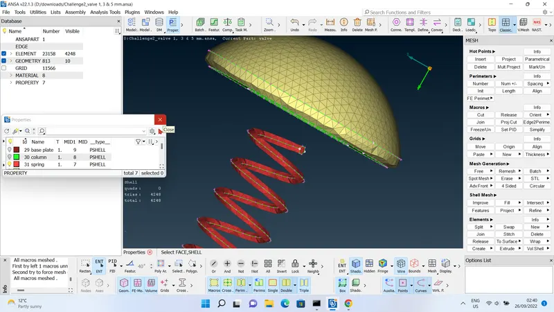
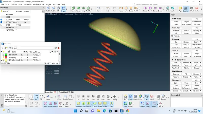
- as we discussed in the challenge 1, firstly enable classic mesh module>> insert the length for perimeter and macros, then insert the mesh element type and target length from mesh properties utility. next select the mesh type to generate mesh. i have meshed the model with 3 different target lengths to observe the results. after a very keen observation valve head and spring are affected areas by changing the target length,as shown below
 .
.
LEARNING OUTCOMES:
- i have learnt to define new surfaces to cleanup and perform checks for the geometry.
- learnt the different options to define surfaces.
- creating PID and allocating PID for different parts of geometry.
RESULTS:
- after meshing with tree different target lengths and comparing them, the meshing with 1mm target length proved effective by acquiring maximum percentage of geometry to obtain better results.