Week 2 Challenge
Answer to the Question No.1
Aim: Aim to the question is how will assign the circular column. and unit system in .std modal file.
Introduction: in this question we have to answer theb following questions:
- How will you assign Circular section to column
- How will you assign Unit system to a .std model file?
- What are the parameters to be specified while using “Bay Frame” option?
- Name few codal standards incorporated in STAAD Pro software.
- How will you specify the design compressive strength for a RCC section?
Procedure:
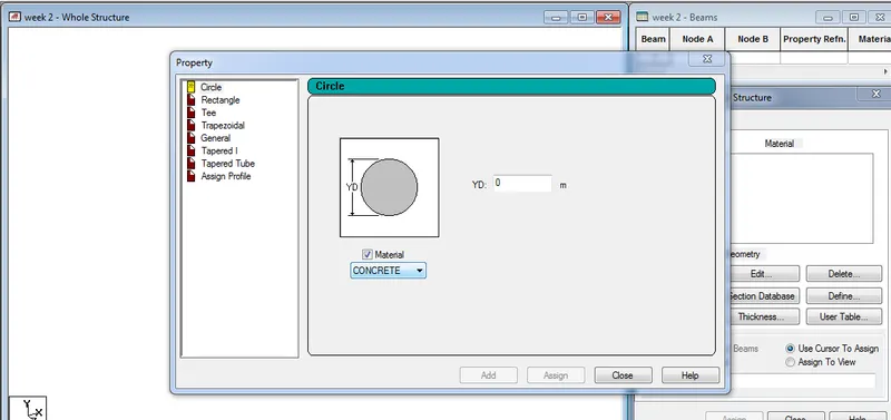
1. How will you assign Circular section to column?
1)Answer:
- Open the staad pro software
- Create modal in the staad.pro
- Go to the properties in that Define parameeters
- Assign the circular Shape of the column
- put the Radious of the Circular coulm
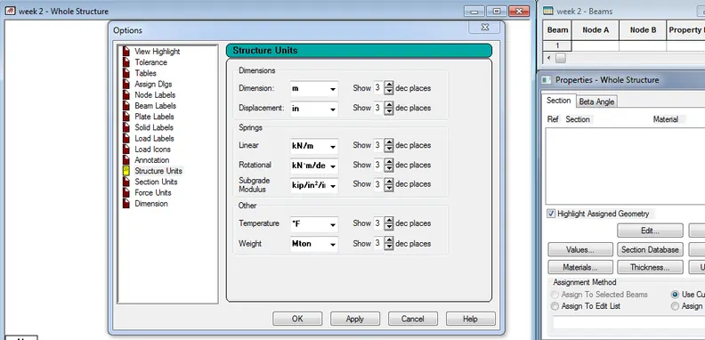
2. How will you assign Unit system to a .std model file?
2)Answer:
- Open the staad pro software.
- Go to the file menu and then settings
- open the structural setting
- change the dimension as the required unit.
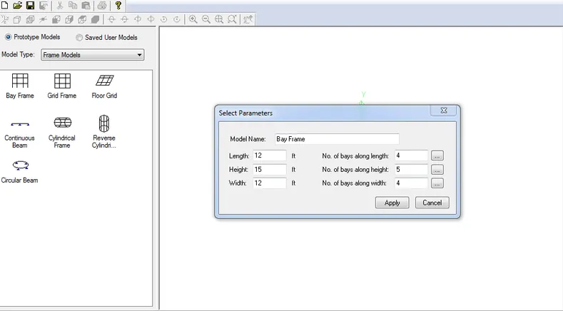
3.What are the parameters to be specified while using “Bay Frame” option?
3)Answer
- We create the parameter of the design by bay frame by clicking on the Structural wizard option
- click on the fram modal option
- next click to the way bay frame
- now enter the parameter like the length, breadth, height and the bay frame along the length
4.Name few codal standards incorporated in STAAD Pro software.
4)Answer:
- In Staad pro the Codal standard are incorporated for the Steel, Concrete, Aluminum.
- For the Steel the codal provision are IS 800 , IS 800 : 2007, IS 800:2007 WSD , IS 801
- For the concrete the Codal provision are the IS 456 and IS 13920 for the Seismic Design
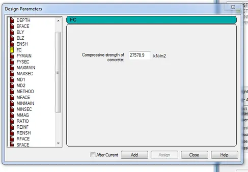
5. How will you specify the design compressive strength for a RCC section?
5)Answer:
- First go to the design option in the tab
- next click on the define parameter
- we see the Fck compressive strength of RCC section is Given as 25000 kNm
Result: I write all the answers of the given question with screenshot which attached with questions and steps
Answer to the Question No.2
Aim: Aim to the question is State the “Input” steps involved in RCC design and also Explain the difference between Fixed and Enforced support condition in STAADPro.
Introduction: in this question, we have to answer the following questions:
- State the “Input” steps involved in RCC design
- Explain the difference between Fixed and Enforced support condition in STAADPro.
Procedure:
1.State the “Input” steps involved in RCC design
1)Answer:
For design RCC we have to input the following steps:
- Geometry: The Node location and the node spacing are given
- Properties: Specify the Sectional properties of the section
- materials: Specify the properties of the material
- Specifications: The specifications are given
- Support: The end support are to be given
- Loading: Need to provide the loading pattern and the loading combination
- Analysis: Need to Analysis the modal and all the Input Specification are Given
- Design: Finally, the Design are to be done
2. Explain the difference between Fixed and Enforced support condition in STAADPro.
2)Answer:
Difference between Fixed and Enforced support conditions in STAADpro.
In STAAD pro Software support displacement loads cannot be applied to such models when the FIXED type of support is specified.
For the Enforced ut type, there is no. provision to specify, there is no provision to specify a spring constant.
The only choices, which are built into the program are zero stiffness.
Result: i completely write State the “Input” steps involved in RCC design and also i Explain the difference between Fixed and Enforced support condition in STAADPro.
Answer to the Question No.3
Aim: In this question we have to Explain the steps involved in analysis of a model using STAAD Pro sequentially.
Introduction: in this question, we have to answer the following questions:
1. Explain the steps involved in analysis of a model using STAAD Pro sequentially.
2. Explain the two ways in which a structural framework/model can be created in STAAD Pro software.
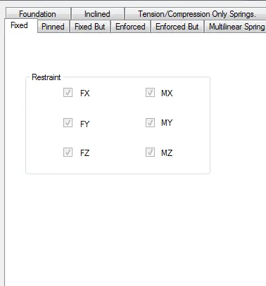
3. Elaborate the different support conditions in STAAD Pro.
4. How will you extract the stress distribution for a staircase slab?
5. Explain the different ways to view SFD & BMD in STAAD Pro.
Procedure:
1. Explain the steps involved in analysis of a model using STAAD Pro sequentially.
1)Answer:
Following steps are involved in analysis of a modal are.
- Before analysis of the modal the load pattern and the load combination are to be provided the modal
- next go to the analysis option
- Define Command
- Select the data for the analysis of the modal by perform analysis.
- this is depends on the support conditions.
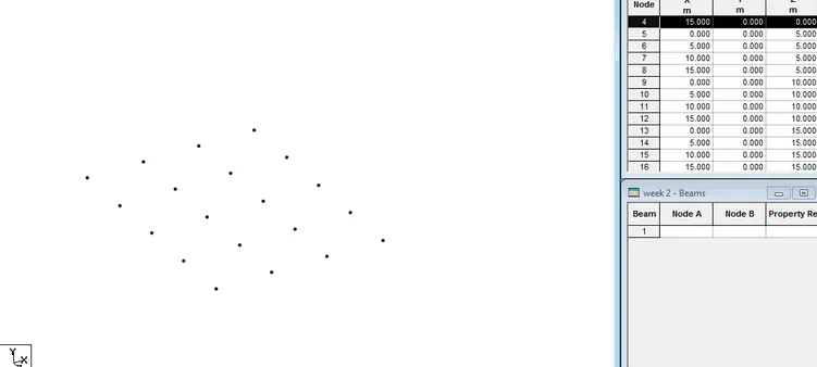
2. Explain the two ways in which a structural framework/model can be created in STAAD Pro software.
2)Answer:
The two ways to model the a structural framework is:
- Creating Modal by Node by Node
- Creating modal by Bay frame by
3. Elaborate the different support conditions in STAAD Pro.
3)Answer
4. How will you extract the stress distribution for a staircase slab?
4)Answer:
- The Design of the Staircase slab is done by Node placement
- The creation of plate is used in stair case
- BY using Generate mesh
- The stress distribution for the staircase slab is done by viewing the color in the slab of the design
5. Explain the different ways to view SFD & BMD in STAAD Pro.
5)Answer:
- After completion of the Design the staad-pro will automatically provide the BMD & SFD
- By Entering to the Post processing process click on ok
- By clicking the beam results Deflection command
- Reaction clicks the beam deflection
Result:I Explain the steps involved in analysis of a model using STAAD Pro sequentially. Also i write all are the answer of the Question.
Answer to the Question No.1
-: PRACTICAL:-
Aim: in this we ave to practice to make the
Introduction: in this question we have to do the followings things:
Simply Supported Beam
a. A Simply supported beam with two point loads symmetrically placed
b. Span L = 20m
c. Load P = 50kN each
d. Both P located at 5m from each support
B.Fixed Beam
a. Span L = 16m
b. Uniformly Distributed Load w=9kN/m
Procedure:
1) Answer:
GIven Data:
a. A Simply supported beam with two point loads symmetrically placed
b. Span L = 20m
c. Load P = 50kN each
d. Both P located at 5m from each support
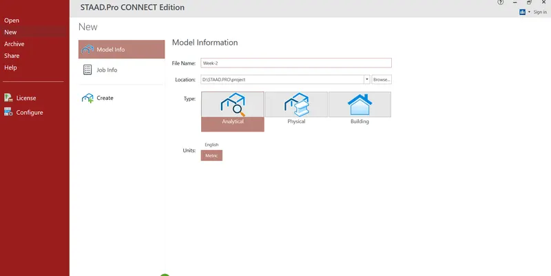
Step-1
- First Open the STAAD PRO software
- Go to Modal Information.
- Select Analytical Modal
- And Select Metric Unit.
Step-2
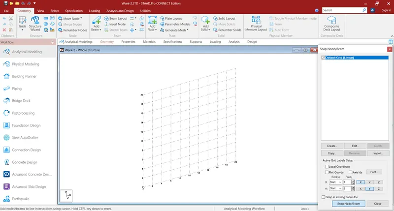
- Go to Grid
- Coose selects to beam
- Select put
Step-3
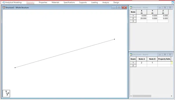
- Creates the notes in geometry tab as per the questions
- Now go to the geometry tab select add beam and draw the beam by using beam cursor
Step-4
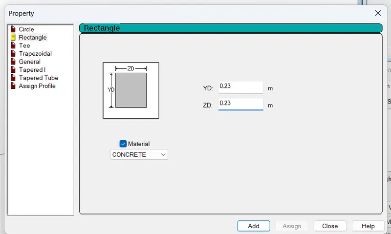
- Click on Define
- Add the section here
- choose rec. and put the data required.
- YD = 0.23 , ZD = 0.23 Mateial = concrete
Step-5
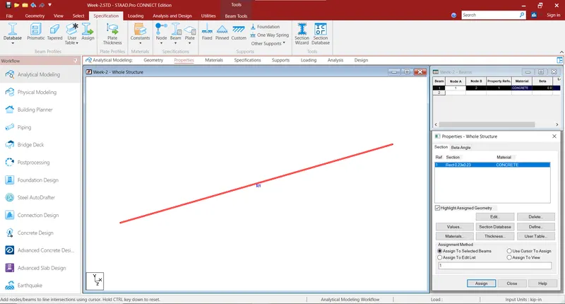
- Now Assign the Mateial
Step-6
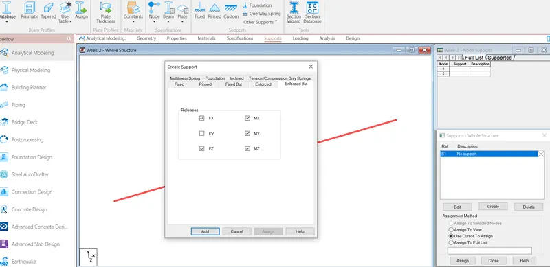
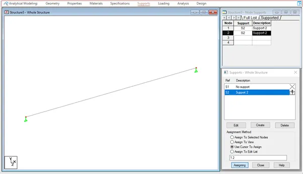
- Select SUPPORTS-TAB
- Supports-Whole Structure dialogue box opens
- Click on create option
- For Roller support, click Create
- select Fixed But and Release FX and MZ
- click Add.
Step-7
- Then to assign Support at the two ends of beam,
- Select Use Cursor to Assign option to assign the supports.
Step-8
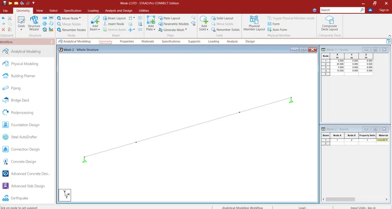
- Go to geometry tab and add nodes at 5m and 15m
Step-9
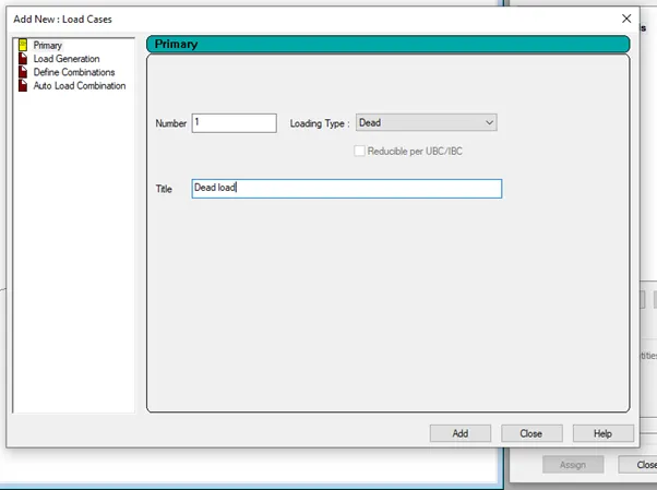
- click Load Cases < Add < Add New : Load Cases.
- Add New: Load Case dialogue box opens.
- select Primary
- Number = 1, Loading Type =Dead, Title = DL.
- Select Dead Load(DL)
Step-10
- Click on Load & Definition Tab
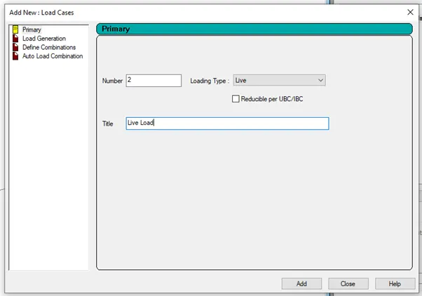
- click Load Cases < Add < Add New : Load Cases.
- Add New: Load Case dialogue box opens.
- select Primary
- Number = 2, Loading Type =Live, Title = LL
- Click on Load & Definition Tab
- click Load Cases < Add < Add New : Load Cases.
- Add New: Load Case dialogue box opens.
- select Primary
- Number = 2, Loading Type =Live, Title = LL
Step-11
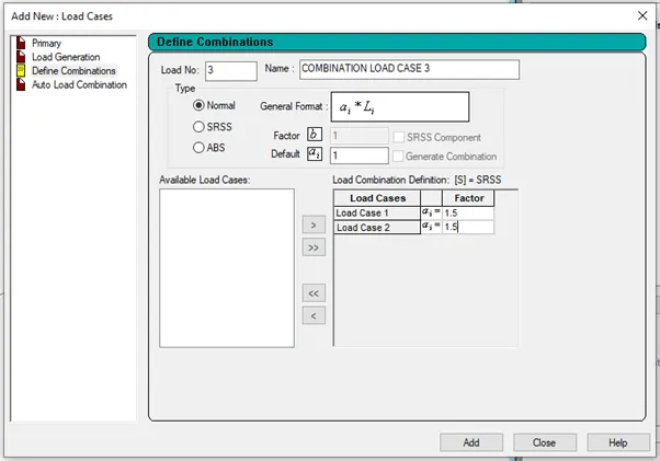
- select Define Combination
- Number = 3,
- Name: Combination oad Case 3
- Factor: 1.5
Step-12
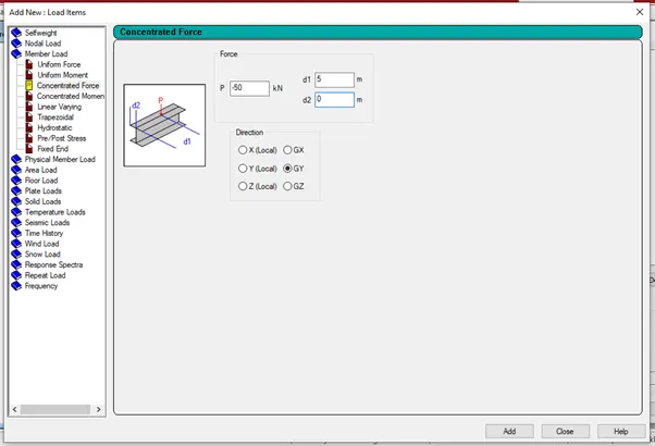
- Select Live Load
Step-13
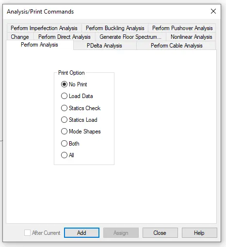
- Click on ANALYSIS TAB
- Analysis-Whole Structure dialogue box opens
- Click on Define Commands
- Analysis/Print Commands dialogue box opens
- Select Perform Analysis
- Print options : No print and
- click Add.
Step-14
- After adding Analysis/print command, click Run analysis.
- Then we should get the Analyzed model with 0 Errors
- select Go to post processing Mode and click Done.

Step-15
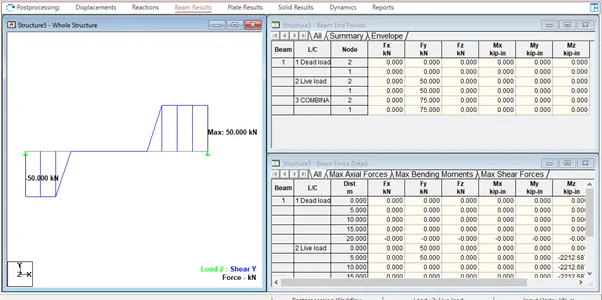
- Go to result tab
- Go to view result
- Check SFD and BMD by Click On SFD And BMD Tool.
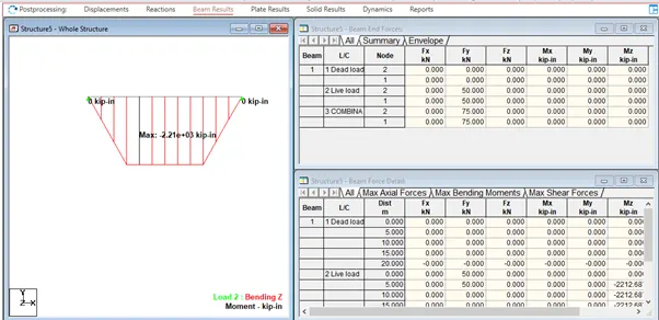
Step-16
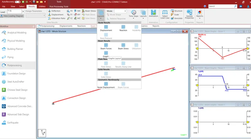
- Click on RESULTS Tab
- Go to View Results Palette
- Click on Layout
- Click on Graph to view SFD and BMD
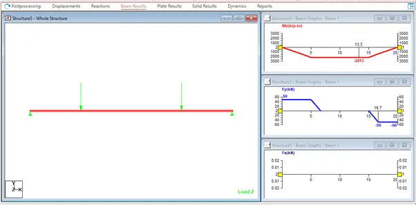
Given Data: B
Step-1
- Fixed Beam
a. Span L = 16m
b. Uniformly Distributed Load w=9kN/m - Open the new STADD.Pro file
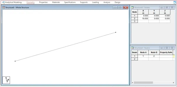
- Create the nodes in geometry tab as per the question
- Click on GEOMETRY TAB
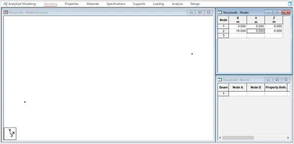
- In Structure Pallette,Select Grids and choose Beam Grid
- Enter the data to create Nodes in Nodes Column
- Node 1 : X=0, Y=0 ,Node 2: X=16, Y=0
Step-2
- Click on Define
- Add the Section here
- Select Rectangle and fill the data required.
- YD= 0.23m, ZD=0.23m, Material = Concrete and
- click Add.
Step-3
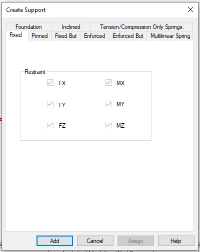
- Select SUPPORTS TAB
- Supports-Whole Structure dialogue box opens
- Click on create option
- select Fixed and click Add.
Step-4
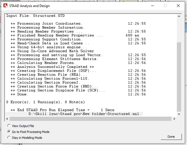
- After adding Analysis/print command, click Run analysis.
- Then we should get the Analysed model with 0 Errors
- select Go to post proccessing Mode and click Done
Step-5
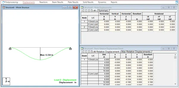
- It will ask us to Select Load Cases and Combinations.
- Select Created DL and LL,
- Click OK to view Displacement of applied Load cases.
Step-6
- Click on RESULTS Tab
- Go to View Results Palette
- Check SFD and BMD by Click on SFD and BMD tool.
- To view SFD of the model select FY icon present at the toolbar.
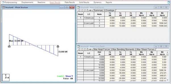
Step-7
- To view SFD of the model select Mz icon present at the toolbar.
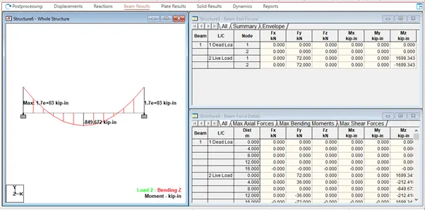
Step-7
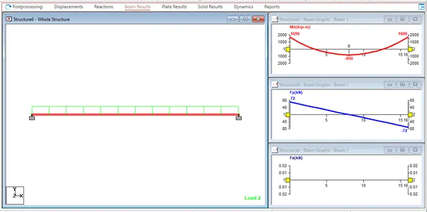
- Click on RESULTS Tab
- Go to View Results Palette
- Click on Layout
- Click on Graph to view SFD and BMD
RESULT:-
- Analyzed the given structural elements and validated the results.
- A. Simply Supported Beam