Week 2 Challenge
AIM:-
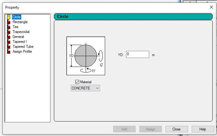
1. 1. How will you assign Circular section to column?
Procuder:-
Answar:-
- First Go toi the Properties
- Than Selct the Define
- Open this Diloge box Properties
- And Give the Radius of the member
- Now Create the Circular Column
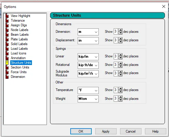
2. How will you assign Unit system to a .std model file?
Answar:-
- First Go toi the View
- Than Selct the Option Display
- Open this Diloge box options
- Than Selct the Structural Units
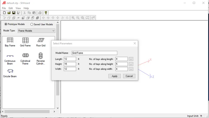
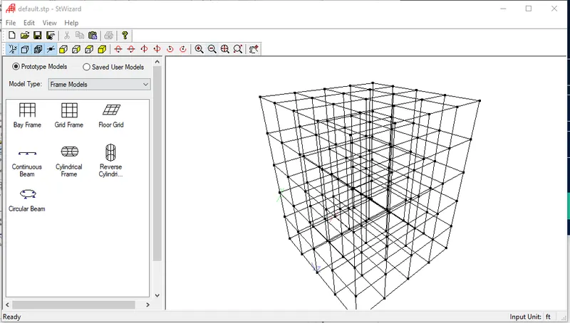
3. What are the parameters to be specified while using “Bay Frame” option?
Answar:-
- Go to geometry tab in that select structural wizard
- that select frame model in that select bay frame
- Give the parameters like length, height, width,
- No. of bays along length, No. of bays along height and No.
- of bays along width
4. Name few codal standards incorporated in STAAD Pro software.
Answar:-
Euro code, ACI, IS code
5. How will you specify the design compressive strength for a RCC section?
Answar:-
- In design select materials as concrete
- select the code and then go to define
- parameters and select FC then specify the value
2) 1. State the “Input” steps involved in RCC design.
Answar:-
- Steps involved in RCC design are
- Geometry
- Properties
- Materials
- Specification
- Support
- Loading and Load combinations
- Analysis
- Design

2. Explain the difference between Fixed and Enforced support condition in STAADPro.
Answar:-
- When the fixed type of support is specified, for those degrees of freedom which are to be treated as fully restrained, STAAD
- assumes the displacements to be known quantities whose value is zero. Hence, these degrees of freedom are not considered
- for the stiffness matrix and their value is not calculated
- When the enforced type of support is specified, for those degrees of freedom which are to be treated as restrained, STAAD
- assign a spring with a spring stiffness – translational stiff springs for translational restraints and rotational stiff springs for
- rotational restraints. Those degrees of freedom which are free to displace are assigned springs of zero stiffness. Hence for all
- the 6 degrees of freedom at such supports, the displacements are calculated. The one which have a stiff spring with end up
- having a negligible displacement and those with zero stiffness springs will have a displacement based on the structure
- geometry, properties and loading
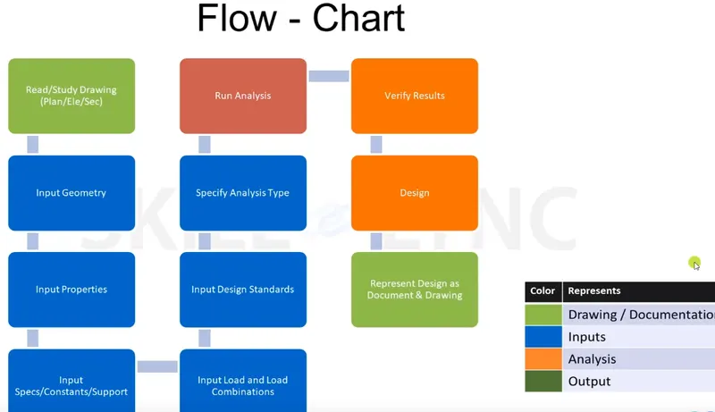
3) 1. Explain the steps involved in analysis of a model using STAAD Pro sequentially.
Answar:-
- Read or study drawings (Plan/Elevation/Section)
- Input Geometry
- Input Properties
- Input Specifications/Constants/Supports
- Run analysis
- Specify analysis type
- Input design standards
- Input load and load combinations
- Verify results
- Design
- Represent design as document and drawing
2. Explain the two ways in which a structural framework/model can be created in STAAD Pro software
Answar:-
- Node by node method
- Grid method
- Structural wizard method
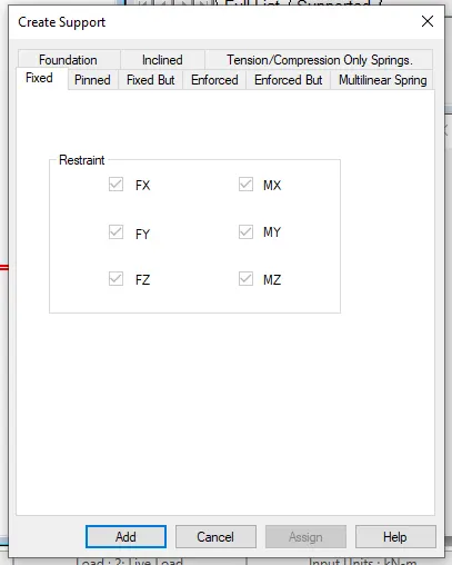
3. Elaborate the different support conditions in STAAD Pro.
Answar:-
- Fixed support
- Pinned support
- Fixed but support
- Enforced support
- Enforced but support
- Multilinear spring support
- Foundation support
- Inclined support
- Tension/Compression Only Springs support
4. How will you extract the stress distribution for a staircase slab?
Answar:-
- Create the staircase by using the nodes in the geometry panel
- After creating the nodes assign the plate elements as the slab property after that define load cases and calculate the area load
- acting on the staircase and apply load cases and load combination to the staircase slab and then create a mesh on the plate element
- After that run the analysis and go to post processing mode and click on plate result option in that select stress distribution
- result and choose the stress type accordingly and that stress distribution result is displayed
- Maximum and minimum stress values are displaced
5. Explain the different ways to view SFD & BMD in STAAD Pro
Answar:-
- After completing the design and running the analysis software will provide the BMD and SFD
After the analysis click on Post processing mode and click OK
- Go to deflection command and click on beam result
In reaction command click the beam deflection
Practical :-
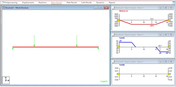
1. Analyze the following structural elements and validate the results
A. Simply Supported Beam
a. A Simply supported beam with two point loads symmetrically placed
b. Span L = 20m
c. Load P = 50kN each
d. Both P located at 5m from each support
Answar:-
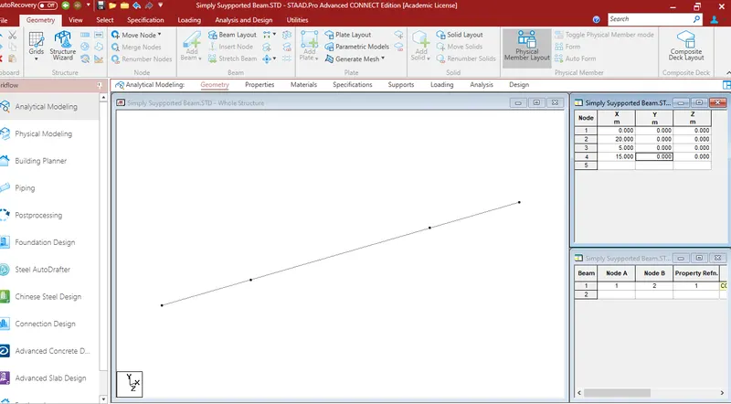
- Open the new STADD.Pro file
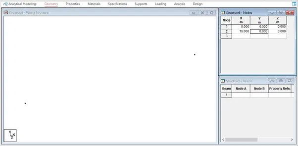
- Create the nodes in geometry tab as per the question
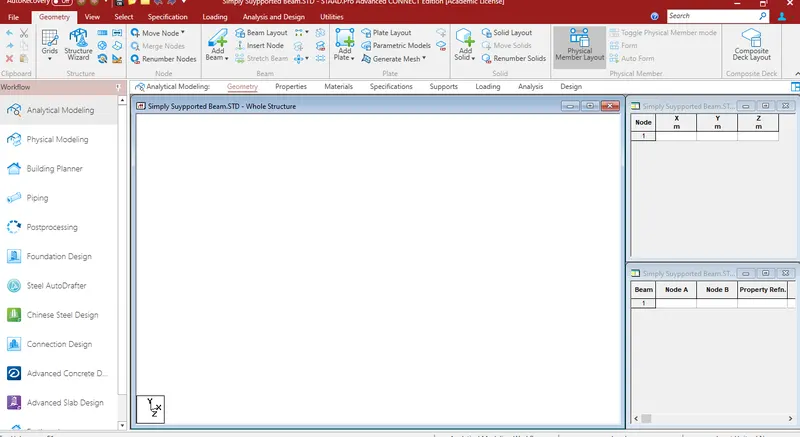
- Go to geomerty tab select add beam and draw the beam by usinf beam cursor

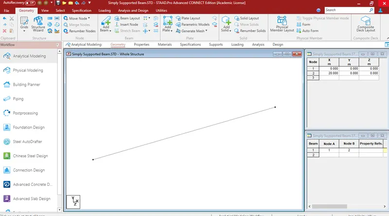
- Go to properties tab and select define and give the rectagular dimensions for the beam
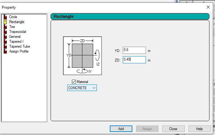
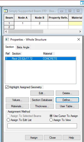
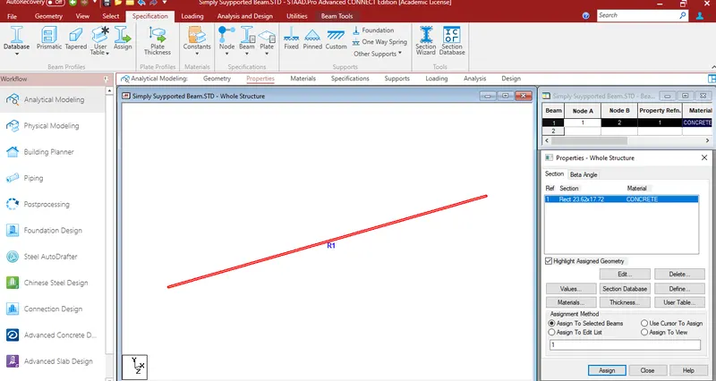
- Select the created beam and assign the rectangular property to the beam
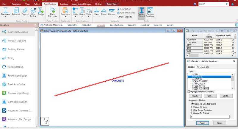
- Go to material tab give the materialas concrete
- As per the question load P is located at 5m from each support
- Go to geometry tab and add nodes at 5m and 15m
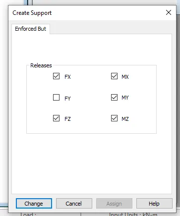
- Go to support tab and create a enforced but supportand click on add and add the support to the beam using node cursor
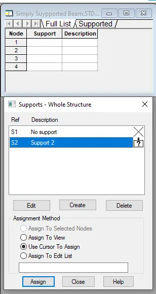
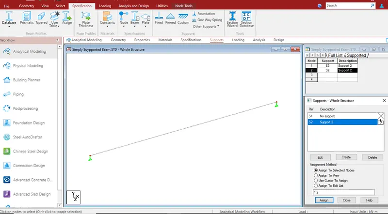
- Go to loading tab add the load cases
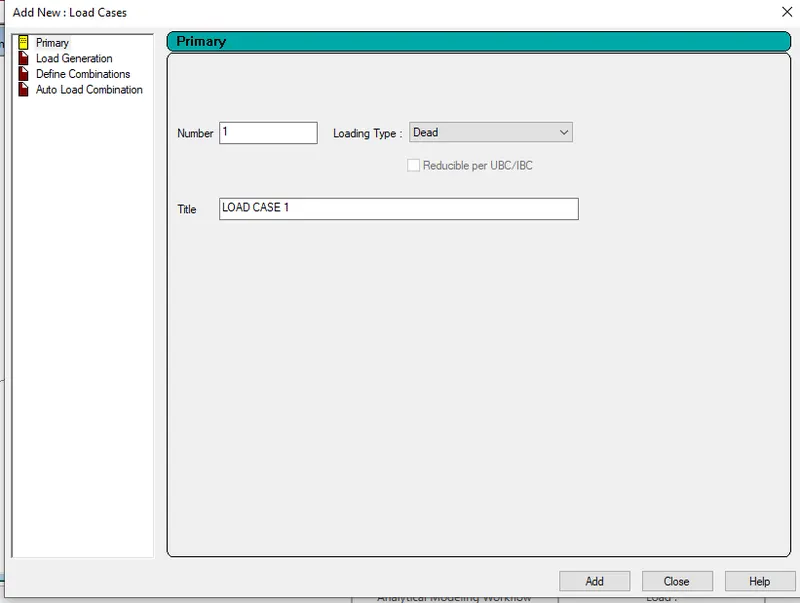
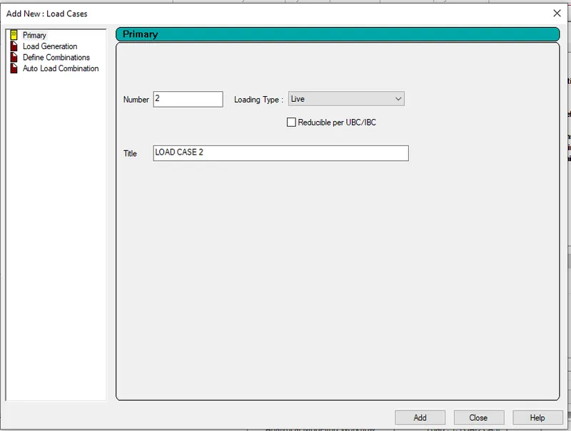
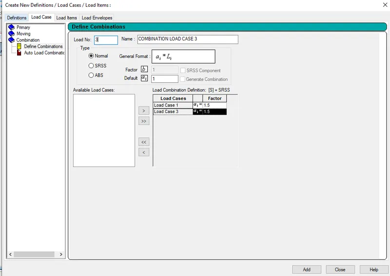
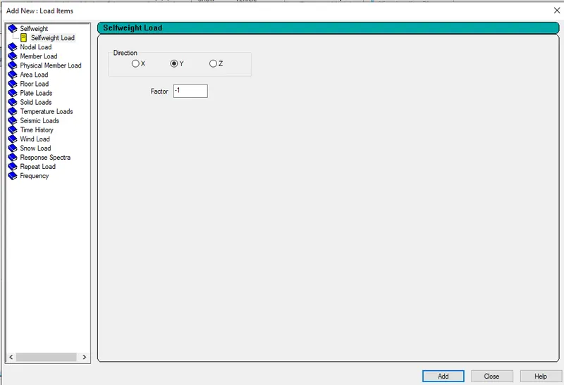
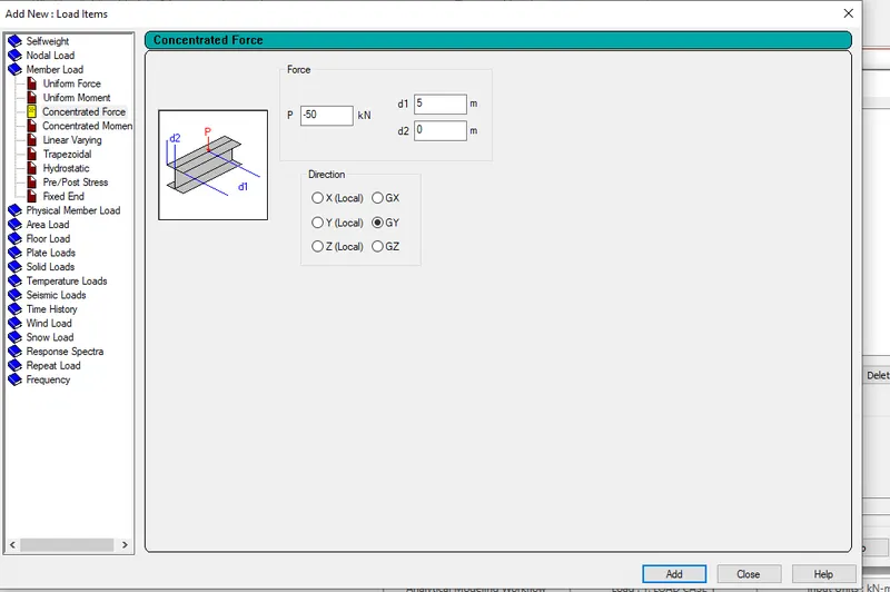
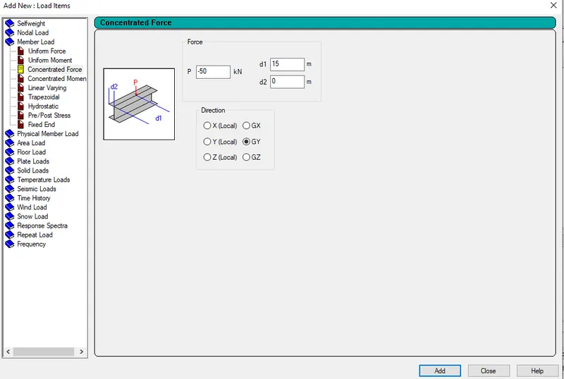
- Assign the loads to the beam using use cursor to assign
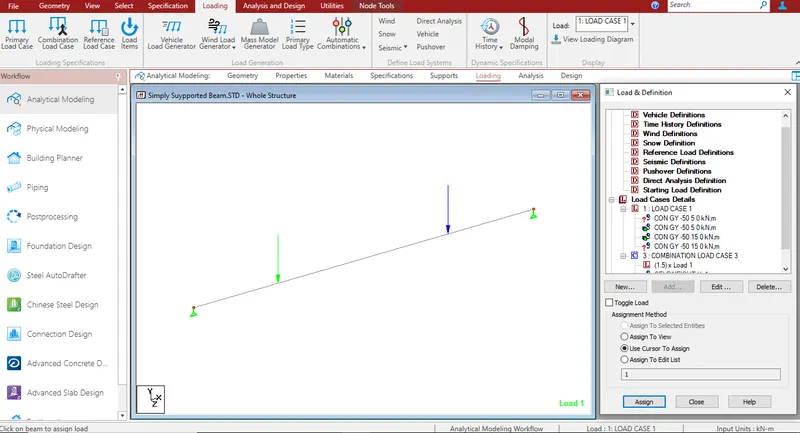
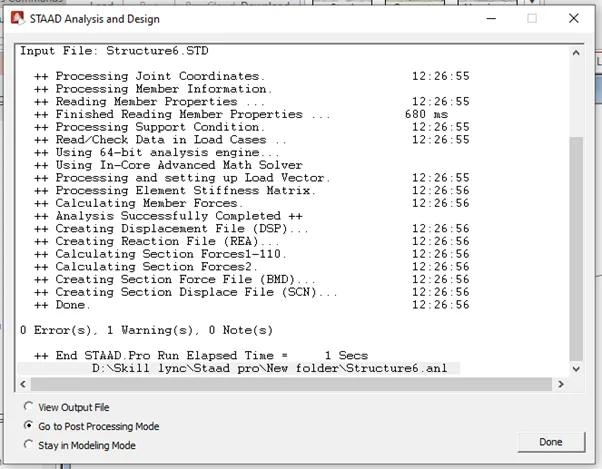
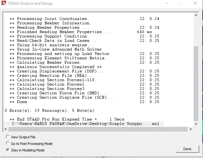
- Go to analysis tab and select analysis command and do perform analysis

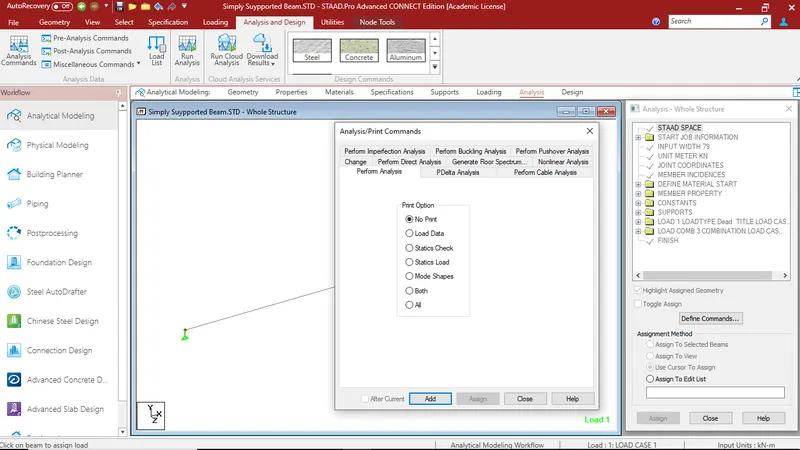
- Run the analyis
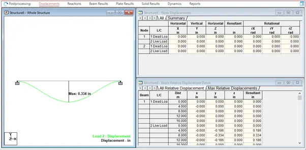
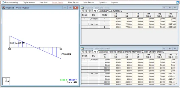
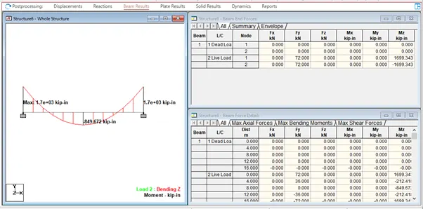
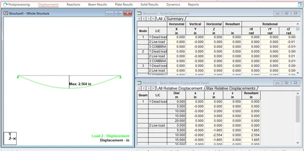
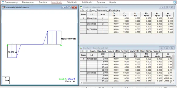
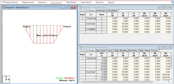
Result:-
B.Fixed Beam
a. Span L = 16m
b. Uniformly Distributed Load w=9kN/m
Answar:-
Ans :-
- Open the new STADD.Pro file
- Create the nodes in geometry tab as per the question
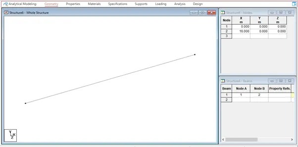
- Go to geomerty tab select add beam and draw the beam by usinf beam cursor

- Go to properties tab and select define and give the rectagular dimensions for the beam
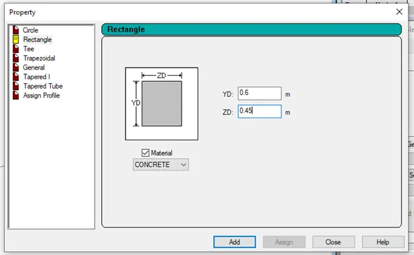
- Select the created beam and assign the rectangular property to the beam
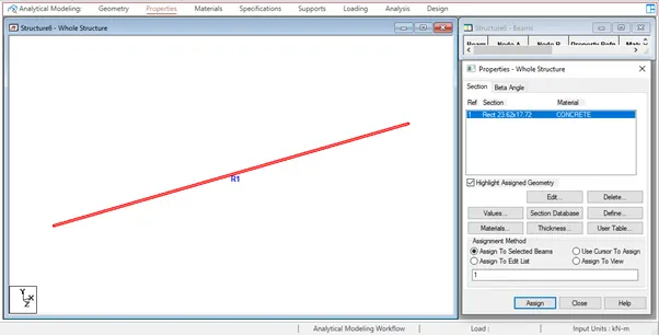
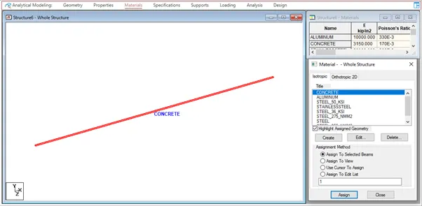
- Go to material tab give the materialas concrete
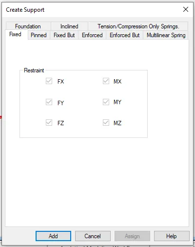
- Go to support tab and create a fixed support and click on add and add the support to the beam using node cursor

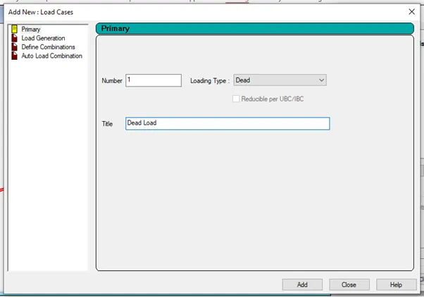
- Go to loading tab add the load cases
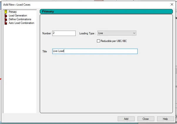
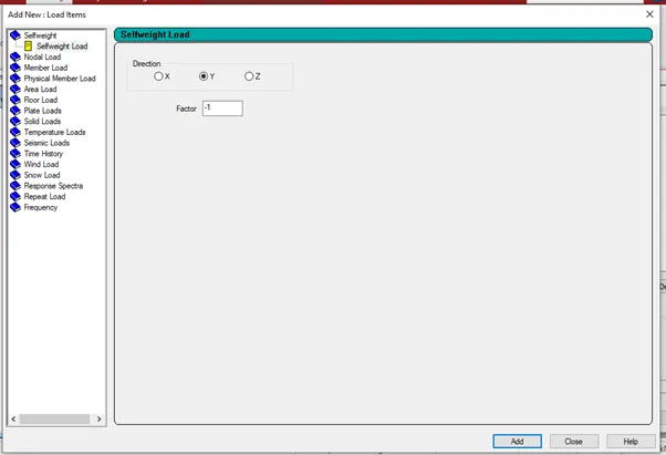
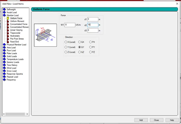
- Assign the loads to the beam using Assign to selected beam
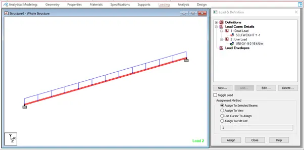
- Go to analysis tab and select analysis command and do perform analysis

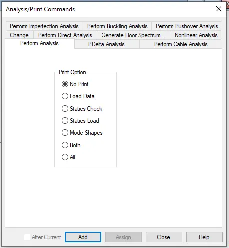
- Run the analyis

Result:-