Week 2 Challenge
Q.1
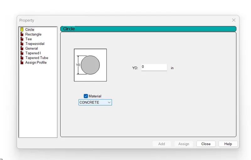
AIM- How will you assign circular section to column?
Assign a circular section for column-
Procedure- Under the properties icon we define the shape of geometry like if we want to select circular column than we will select circular shape and set its diameter.
Q.1B
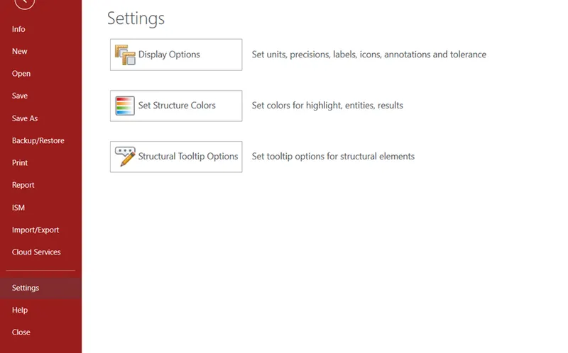
AIM- How we can assign unit system in std.pro?
Procedure-
- Open the file tab select new model, here we will see the model information under this model information we can set units of model like English and Metric unit.
- File tab choose setting option here we can also set units.
Q.1C
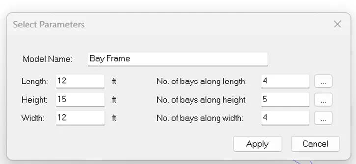
AIM- What are the parameter to be specified while using bay frame option?
PARAMETER UNDER THE BAY FRAME-
- Length, height, Width and No. of bays along length, No. of bays along height, No. of bays along width
Q.1D
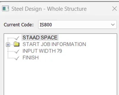
AIM- Name of few codal standard incorporated in stadd pro software.
Standard code incorporated in std.pro-
IS456 – For reinforced concrete design
IS800 – For steel structure design
Q.1E
AIM- Design compressive strength specify for RCC section.
Procedure-
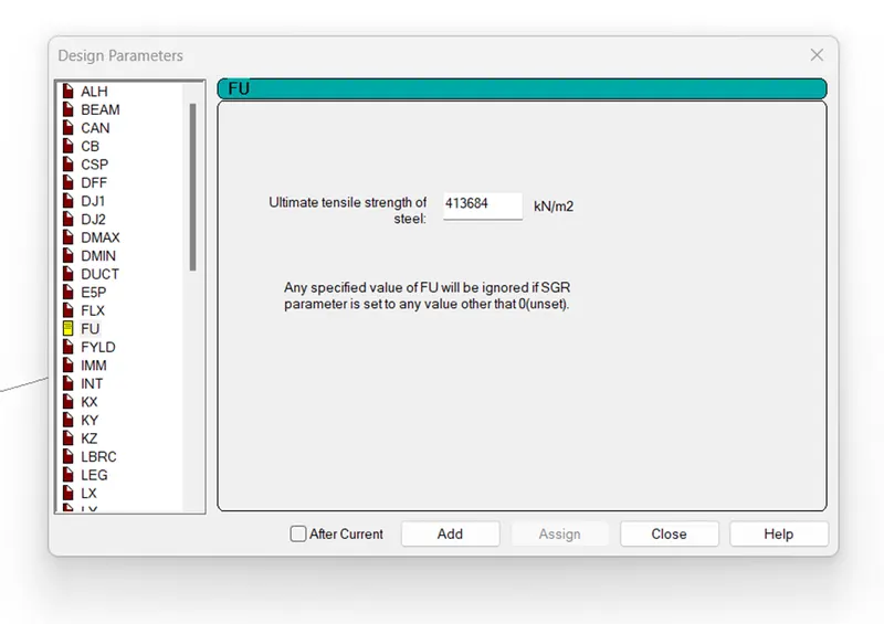
- In menu bar we will select the Design tab under this design tab we click on define parameters.
- Now we see that a dialogue box opened here we can choose any parameter to design RCC section. Here we can also choose compressive strength (fck) of RCC section.
Q.2
AIM-What is the input step involved in RCC design?
RCC Design input step-
- Geometry- In first step geometry of member design with the use of nodes like beam section, column section etc.
- Properties- Properties of any geometry have to decide after geometry option IN this nproperty option we give the width and depth of geometry and assign the shape of property.
- Material- Next we assign the material of section like wood, concrete etc.
- Specification- We can set specification of section and can edit specification of any structure component.
- Supports- Here we add the support to geometry like fixed support, hinge support, roller support etc.
- Loading- After setting of support of any member we will assign the loads to the member like live load, dead load, wind load, earthquake load etc.
- Analysis- Analysis step give us a opportunity to analysis of structure mean we can calculate here Bending moment, shear force, deflection and can show BMD and SFD of any beam section.
- Design- Under this step we able to design any member of structure.
Q.2B
AIM- Explain the difference between fixed support and enforced support condition in std.pro.
FIXED SUPPORT-
- In fixed support no displacement occurs.
- Degree of freedom on fixed support is zero.
Enforced support-
- Enforced support also work as fixed support but Enforced but support work differently compare to fixed support.
- In Enforced but support we can set displacement of support.
Q.3
AIM- Explain the step involved in analysis of model using stadd pro sequentially.
Procedure-
- Firstly we set the shape and properties of any structure component.
- After assign loading on the structure component and analysis it.
- We choose the option analysis in stadd and perform the analysis like linear analysis, Pdelta analysis, cable analysis
- We run the analysis and find out the results like for beam we can take BMD AND SFD and we can also show the displacement of beam etc.
Q.3B
AIM- Explain the two ways in which a structural framework/model can be created in stadd pro software.
Method of Structural framework/model –
- Nodal table method
- Bay frame method
Q.3C
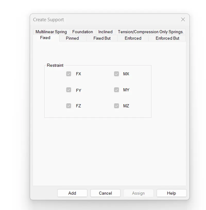
AIM- Elaborate the different support condition in stadd pro.
Support conditions-
- Fixed support
- Fixed but support
- Enforced support
- Enforced but support
- Pinned support
- Inclined support
- Foundation
- Tension/Compression Only Springs
Q.3D
AIM-How will you extract stress distribution for a stair case slab?
Procedure-
- With the use of node we create a free standing stair case.
- Next we provide properties, support, loading condition on stair.
- Now we create the analysis for staircase under the plate result option.
- Under the plate result we can show different type of stress condition like Max. absolute stress, Max. top principal major stress in the form of colour variation.
Q.3E
AIM- Explain the different ways to view SFD and BMD in stadd pro.
- Under the Analysis tab when we done the analysis we take the results like reaction, Moment and SFD,BMD directly.
- We can also take the results under postprocessing option.
PRACTICAL QUESTION
AIM-
Analyze the following structural elements and validate the results
A. Simply Supported Beam
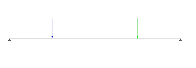
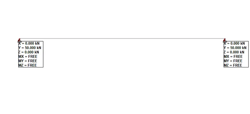
a. A Simply supported beam with two point loads symmetrically placed
b. Span L = 20m
c. Load P = 50kN each
d. Both P located at 5m from each support
INTRODUCTION-
- In stadd pro we can analysis any structure and can get results related to structure.
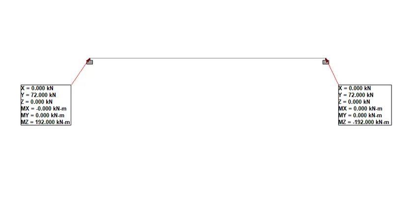
- For the given beam detail we calculate all the reaction and moment which is generated in beam by stadd software.
Procedure-
- Go to the file option and select new model with appropriate name, geographic location and appropriate unit.
- Set the origin of node and set the 20m node in x-direction and create a beam between the node.
- Select properties tab and define the properties for beam like size and shape of beam.
- Set the material concrete for beam.
- Fix the support to beam if we want to create simply supported beam than add hinge support to beam.
- Apply point load of 50 KN in downward direction 5m from both the support.
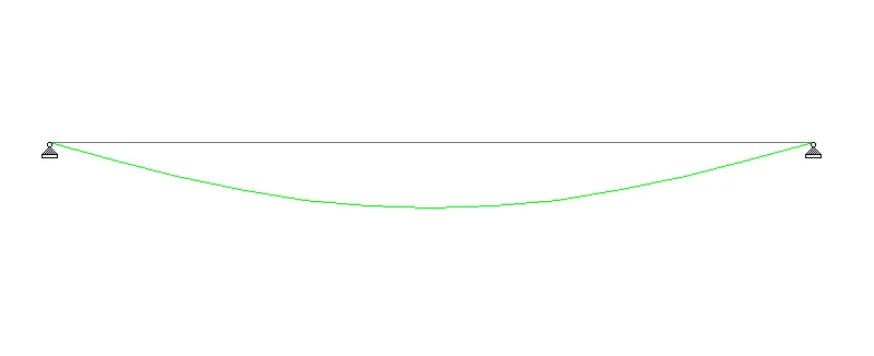
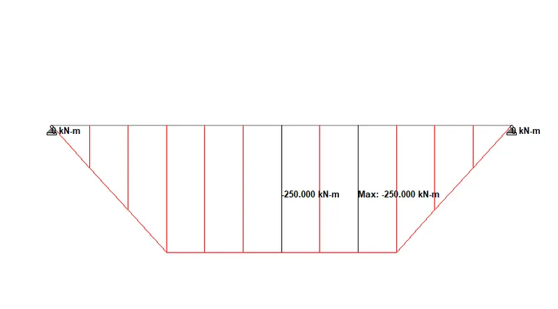
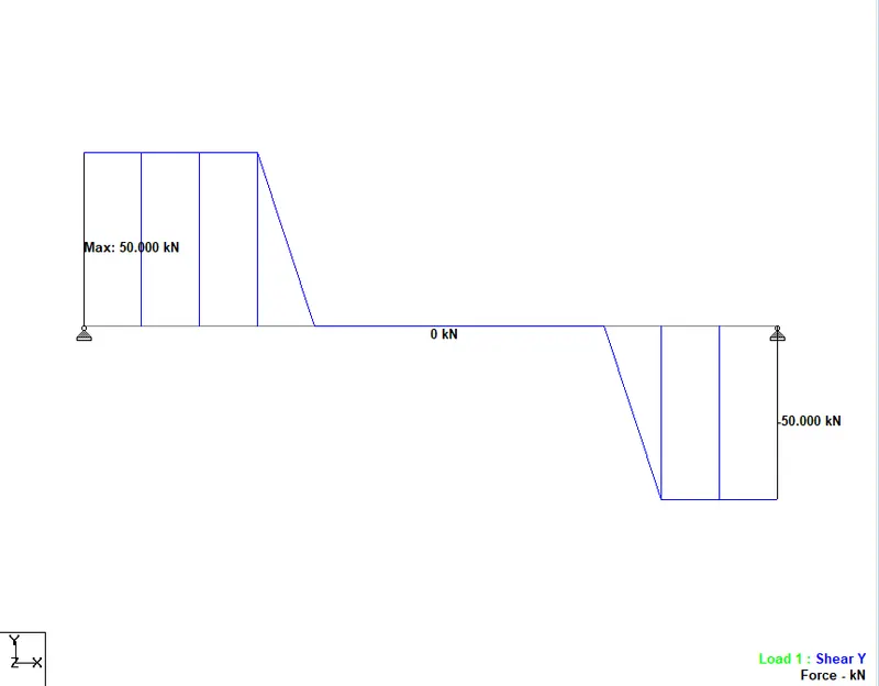
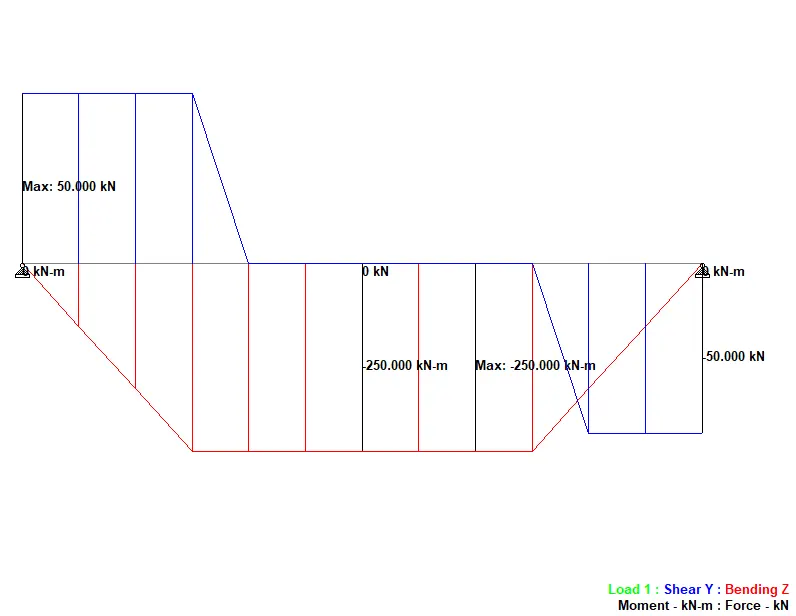
- Analysis the beam for loading condition under analysis tab and extract the result like reaction value, moment value and shear force diagram and bending moment diagram and displacement etc.

RESULT-
For simply supported beam stadd pro gives all the results which is used to design a beam like SFD, BMD and deflection etc.
FIXED BEAM ANLYSIS-
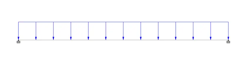
AIM- Analysis a fixed beam of
a. Span L = 16m
b. Uniformly Distributed Load w=9kN/m
INTRODUCTION-
- In stadd pro we can analysis any structure and can get results related to structure.
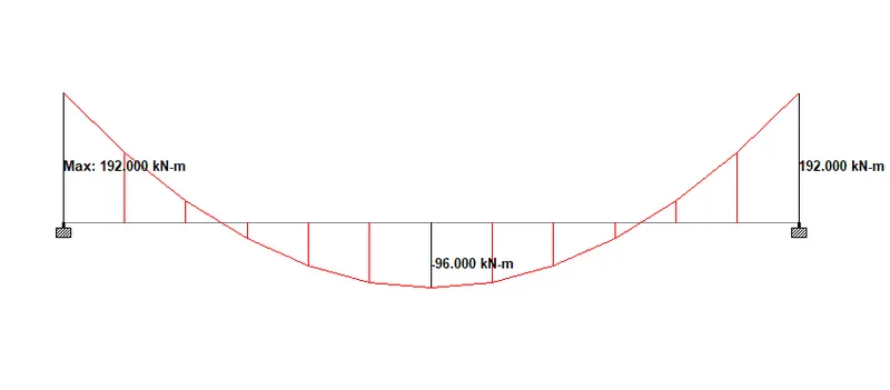
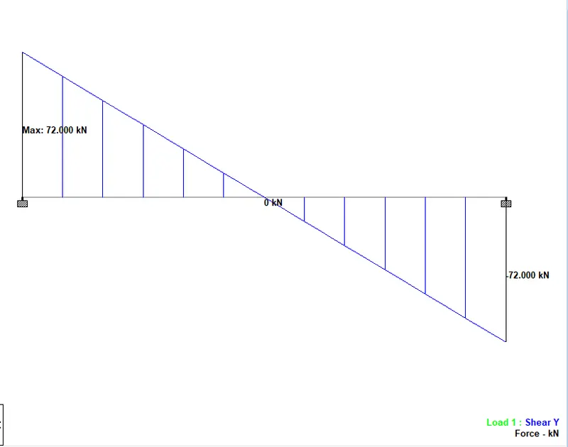
- For the given beam detail we calculate all the reaction and moment which is generated in beam by stadd software.
Procedure-
- Go to the file option and select new model with appropriate name, geographic location and appropriate unit.
- Set the origin of node and set the 16m node in x-direction and create a beam between the node.
- Select properties tab and define the properties for beam like size and shape of beam.
- Set the material concrete for beam.
- ADD the support to beam if we want to create Fixed supported beam than add fixed support to beam.
- Apply UDL of 9 KN/M in downward direction.
- Analysis the beam for loading condition under analysis tab and extract the result like reaction value, moment value and shear force diagram and bending moment diagram and displacement etc.
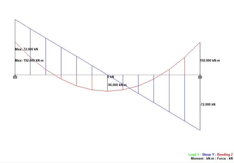
RESULT-
For simply supported beam stadd pro gives all the results which is used to design a beam like SFD, BMD and deflection etc.