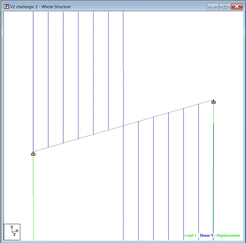
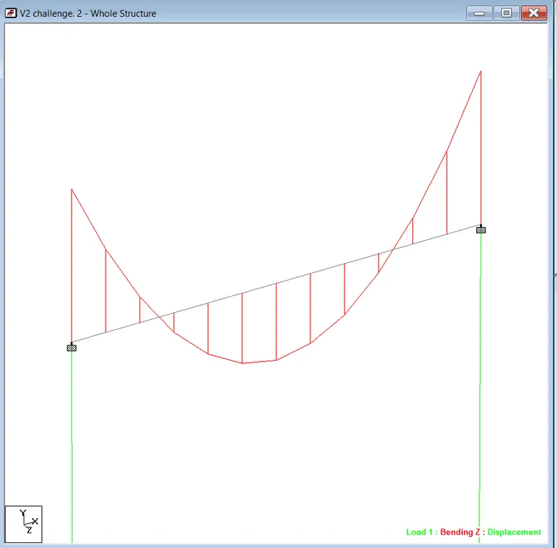
Week 2 Challenge
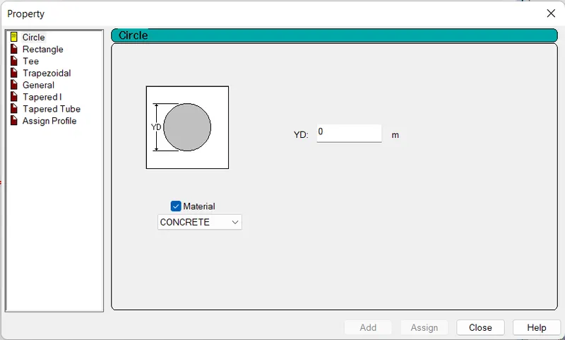
- How will you assign Circular section to column?
- Click on properties icon.
- Here we have to click on define.
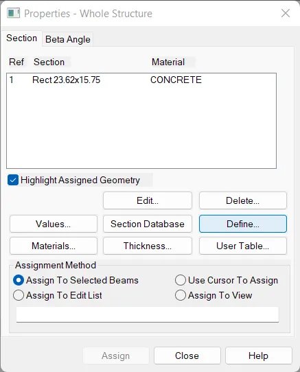
- A dialogue box will appear.
- From here, select the circular section.
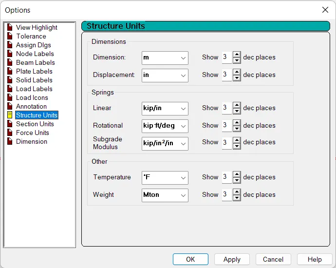
- How will you assign Unit system to a .std model file?
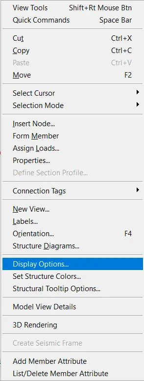
- Right click on the display option.
- From here, select the structural unit.
- What are the parameters to be specified while using “Bay Frame” option?
- Length of frame
- Height of frame
- Width of frame
- Number of bays along length
- Of bays along height
- Of bays along width
- Name few codal standards incorporated in STAAD Pro software.
There are mainly 3 codes used
- Is code.
- Euro code.
- ACI code.
- How will you specify the design compressive strength for a RCC section?
The compressive strength of RCC section. Can be designed by using Is code for 56.
- In STAAD Pro we can design it from Design tab.
- Select concrete.
- For compressive strength, click on FC. Structured. Then Enter the value.
- State the “Input” steps involved in RCC design.
- Geometry- First, we have to create the geometry as pr architectural drawing in the geometry tab of the staad pro
- Properties- In the property we have to define the member shape and size for column beam slab
- Materials- We to define the material of member such concrete steel timber etc
- Specifications- Any special designations to be followed while analysing are mentioned in this section.
- Supports- In this we can assign support to the member like fixed, pinned, roller
- Loading- We have to define the type of load to the structure at any direction
- Analysis-Computational analysis is executed based on the selected method in the software
- Design- Finally, the building sections are designed and the area of reinforcements is extracted via design report

- Explain the difference between Fixed and Enforced support condition in STAADPro.
- Fixed support.
In the Fixed support condition, the translational and rotational movement are restraint means end condition where all degrees of freedom are restricted in the horizontal, vertical and lateral movement. Staad assumes the displacement to be known quantities whose value is zero. Hence, those degrees of not considered for the stiffness matrix, and their value is not calculated.
- Enforced support.
In the enforced support condition, the degree of freedom is restrained. The software considers these as springs of high stiffness as opposed to fixed supports. It is only essential to define supports as enforced when you have FE models involving plates/solids and for which you need to impose support displacement loads
- Explain the steps involved in analysis of a model using STAAD Pro sequentially.
- You need to prepare the geometry tab.
- Then specify the properties tab.
- Then assign the materials tab.
- Run Design Tab
- Assign specifications tab and run analysis.
- Explain the two ways in which a structural framework/model can be created in STAAD Pro software.
- Node system.
Node is simply defined as a point. A point where boundary condition applied, Stiffness of structure are changed, materials discontinuities, Geometrical discontinuities etc..
- Structural wizard method.
Structure Wizard Used to parametrically generate a structural model and then transfer and superimpose it on the current structure in STAAD.Pro. Opens when Geometry > Run Structure Wizard is selected in the STAAD.Pro window.
- Elaborate the different support conditions in STAAD Pro.
- Multilinear Spring
- Foundation
- Inclined
- Tension Compression Only Spring
- Fixed
- Pinned
- Fixed But
- Enforced
- Enforced But
- How will you extract the stress distribution for a staircase slab?
- Create the model of stair case
- Add plate and define the section as a plate element
- Assign and specify the material
- Generate quadrilateral messing for it
- Assign the fixed support and define the load cases and combination
- Add the plate load and self-weight
- Analysis the modal then goes to post processing
- Check plate result and stress
- Stress distribution result will be shown in different colour for different zone
- Explain the different ways to view SFD & BMD in STAAD Pro.
For view SFD and BMD in Staad Pro. We have to follow these steps.
- First we have to do analysis. In the Staad Pro
- Click on the post processing icon in the left side of your screen in the Staad Pro
- Then from the results tab.
- You can specify the BMD and SFD.
Practical
1. Analyze the following structural elements and validate the results
A. Simply Supported Beam
Given:
a. A Simply supported beam with two point loads symmetrically
b. Span L = 20m
c. Load P = 50kN each
d. Both P located at 5m from each support
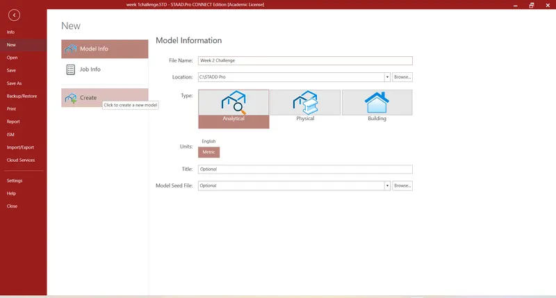
Step 1: Open the new model Staad Pro
- Name the model.
- Click on create.
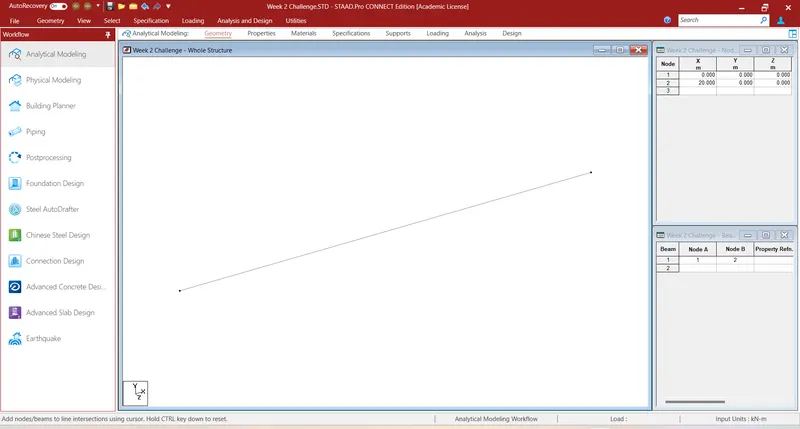
Step 2. Drawing the beam of 20 m.
- With the help of notes. We have draw 20 metres span beam.
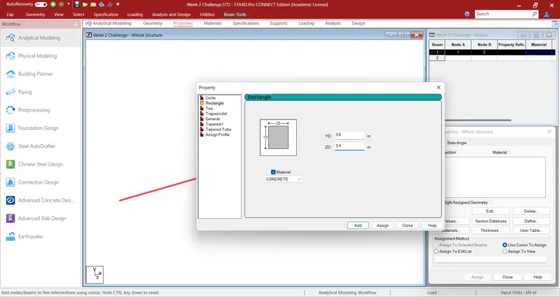
Step 3. Assigning the Properties.
- Click on properties tab.
- Click on define.
- Select rectangular section and enter the value.
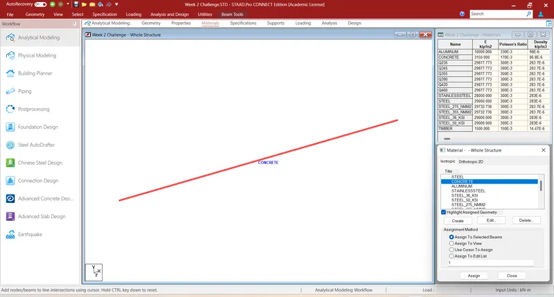
- Now select the beam and click on assign to the selected beam.
Step 4. Assigning the supports.
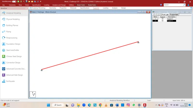
- Click on support tab.
- Now click on create.
- Now Add the fixed support.
- Now select the assigning using cursor. And. Assign the support. On the every end of the beam.
Step 5. Assigning the loading.
- Click on loading tab.
- Click on load case detail.
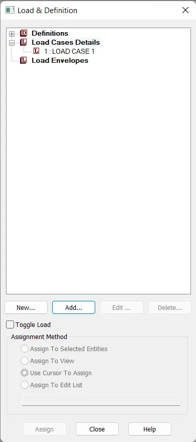
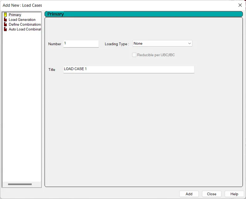
- Now click on add and name. Load case one from the none properties.
- Now add concentrated load.
- Assign it to the Beam
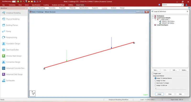
Step 6. Run the analysis.
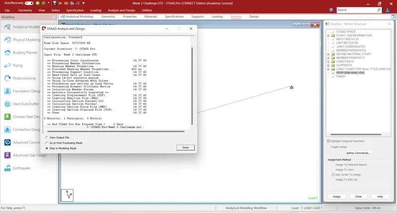
- Click on analysis and details tab from the title box.
- Define the commands.
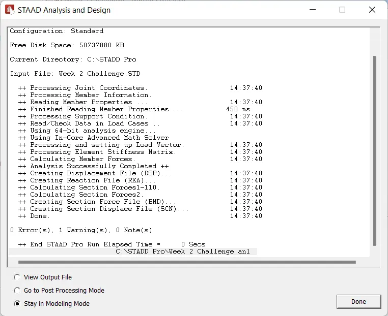
- Now click on the run analysis.
- After analysis, check the results, there should be no errors.
Step 7. Drawing SFD and BMD.
- Click on. Post processing icon on your left side.
- Now select the load case and click on apply.
- From the results step you can. See the SFD and BMD.
B.Fixed Beam
a. Span L = 16m
b. Uniformly Distributed Load w=9kN/m
Procedure:
Step 1: Open the new model Staad Pro
- Name the model.
- Click on create.
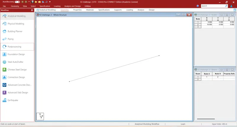
Step 2. Drawing the beam of 16 m.
- With the help of notes. We have draw 16 metres span beam.
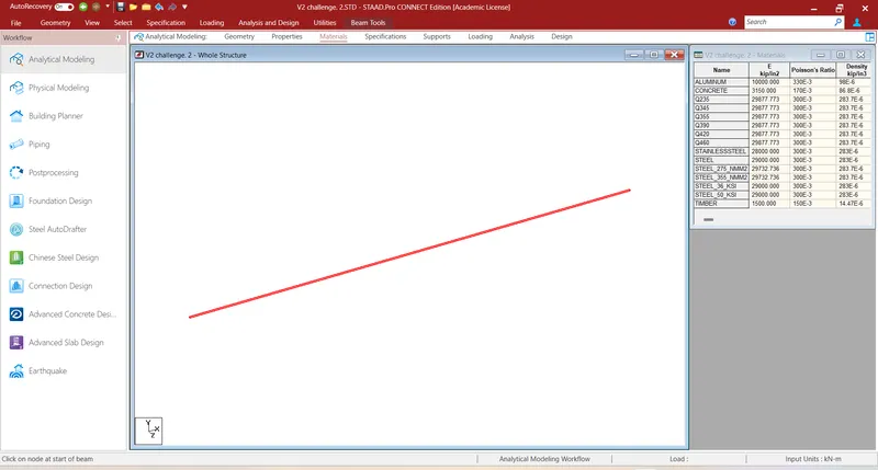
Step 3. Assigning the Properties.
- Click on properties tab.
- Click on define.
- Select rectangular section and enter the value.
- Now select the beam and click on assign to the selected beam.
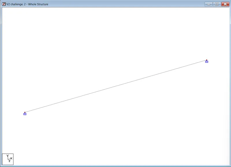
Step 4. Assigning the supports.
- Click on support tab.
- Now click on create.
- Now Add the fixed support.
- Now select the assigning using cursor. And. Assign the support. On the every end of the beam.
Step 5. Assigning the loading.
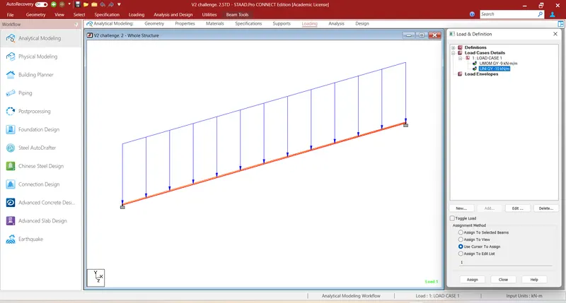
- Click on loading tab.
- Click on load case detail.
- Now click on add and name. Load case one from the none properties.
- Now add Uniform
- Assign it to the Beam
Step 6. Run the analysis.
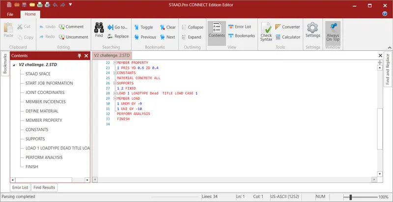
- Click on analysis and details tab from the title box.
- Define the commands.
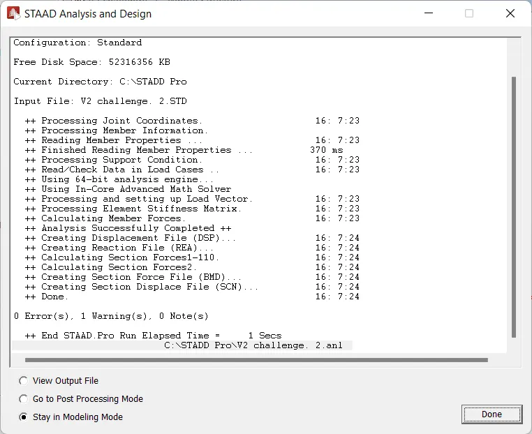
- Now click on the run analysis.
- After analysis, check the results, there should be no errors.
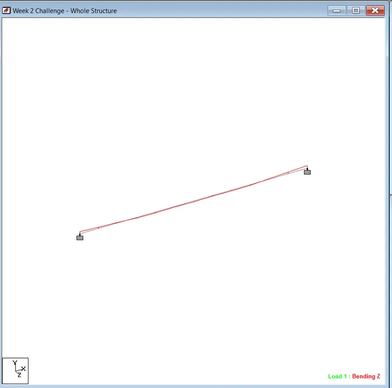
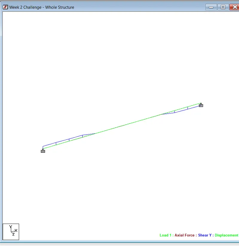
Step 7. Drawing SFD and BMD.
- Click on. Post processing icon on your left side.
- Now select the load case and click on apply.
- From the results step you can. See the SFD and BMD.