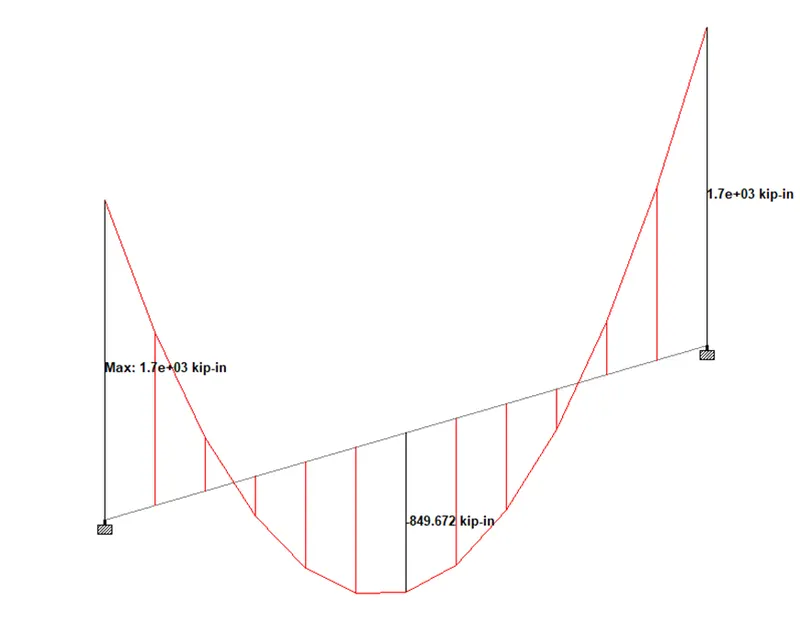
Week 2 Challenge
1.
a. How will you assign the Circular section to a column?
Ans:
- Create a new model for the column
- Create the geometry first enter the origin (0,0,0) for the first node in the node table
- since it is a column (vertical member) you should copy-paste the 2 nd node in the Y direction
- Next, specify the property as we want to select the cross-section of the column since it is a circular column we want to provide the diameter of the column
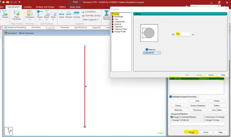
- click ok now the property for the column has been created now you can assign the property to the member
- Now the circular column has been created.
b. How will you assign the Unit system to a .std model file?
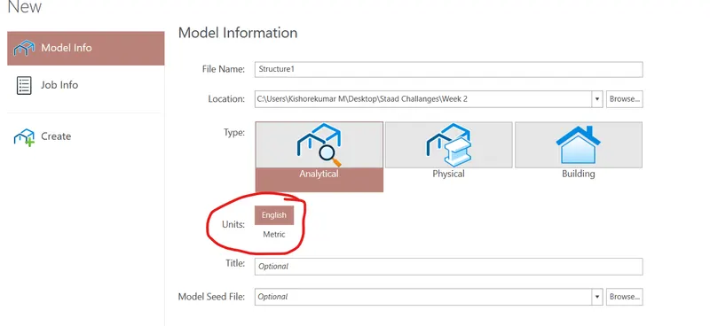
Ans: We can assign the unit system for a model in two ways in the initial stage of creating the model and also after
creating the initial model we can change the units with the menu options
you can choose the unit systems with which the model has to be created whether as a metric system or an English unit system
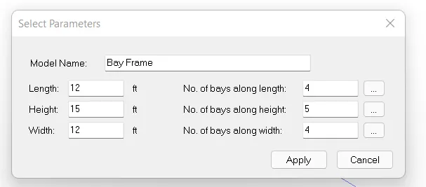
c. What are the parameters to be specified while using “Bay Frame” option?
Ans: Structure wizard is an option provided by default in staad pro to create the model at an easy process
Goto--> Geometry ---> structure wizard ---> select frame models from the model type drop-down list and select the Bay frame option
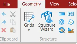
After selecting the option you want to input the parameters like length of the building, width, height, No of bays along the length, No of bays along the height, No of bays along the width as shown in the image below
d. Name a few codal standards incorporated in STAAD Pro software.
Ans:
- Euro Codes.
- American Codes.
- ACI Codes.
- IS codes.
- BS Codes.
- ASCE Codes.
- CAN/CSA Codes.
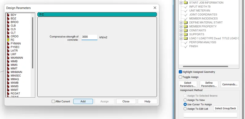
e. How will you specify the design compressive strength for an RCC section?
Ans:
- First click on the analysis and design panel there select the design option
- When the design option is selected then the steel design whole structure dialogue box open
- Then change the design from steel to concrete in the ribbon tab
- Then select the IS 456 code from the current code tab
- Then click on the design parameters
- Then select the compressive strength of the concrete, The compressive strength of concrete notation is Fc
- Enter the value into the tab
- For Ex:- If we want to assign the compressive strength as M-30 then give the 3000KN/m^2 value
- After assigning the value click on add then click on close
2.
a. State the “Input” steps involved in RCC design.
Ans:
- Geometry.
- Properties.
- Materials.
- Specifications.
- Supports.
- Loading.
- Analysis.
- Design.
- GEOMETRY: So the geometry panel mainly deals with the initial part of the modeling in the STAAD Pro software. In the geometry panel, we can draw the entire building using the geometry panel. The whole building is drawn within the geometry input as per the Architectural layout that we have received.
- Properties: So in the Properties panel we assigned the various properties to the model like beams, columns, plates, etc using this property panel.
- Materials: As the name suggests, we assigned different materials to the model using the material panel.
- Specifications: In the specification panel we assigned the designations that were to be followed while analyzing.
- Supports: In this panel, we assign the base supports and the boundary conditions. All the things that are related to the loadings that we are going to assign in the model are done in this loading panel.
- Analysis: In the analysis panel, the computational analysis is executed. After doing the above steps we need to analyze the building for its safety of the building and this analysis of the building is to be done in the analysis panel.
- Design: The final step in modeling in STAAD Pro software is the Design. So after doing the analysis, the building sections are designed and the detailed reinforcement design according to the design that we have done so far is extracted through design input.
b. Explain the difference between Fixed and Enforced support conditions in STAADPro.
Ans:
The FIXED type of support is specified, for those degrees of freedom that are to be treated as fully restrained, STAAD assumes the displacements to be known quantities whose value is zero.
When the ENFORCED type of support is specified, for those degrees of freedom that are to be treated as restrained, STAAD assigns a spring with a very high spring stiffness. Those degrees of freedom that are free to displace are assigned springs of zero stiffness. Hence, for all the 6 degrees of freedom at such supports, the displacements are calculated.
3.
a. Explain the steps involved in the analysis of a model using STAAD Pro sequentially.
Ans: STAAD Pro Analysis Solution Steps
The two ways in which a structural framework/model can be created in STAAD Pro software are:
- Node by Node method.
- Structure wizard method.
NODE-BY-NODE:
- So the first way to model a building is by adopting the node-by-node method.
- In this method, we assign the nodes as per the architectural drawings that are placed manually by placing the coordinates.
- We can assign the nodes to our building by using the geometry panel.
- And these nodes can be transitionally repeated based on the building dimensions and the levels.
STRUCTURE WIZARD:
- So the second method is the structure wizard method to model a building.
- This method is an automated method as compared to the node-by-node method.
- We can create trusses, frames, and other structures just by using this method.
There are different support conditions which are available in the standard pro they are,
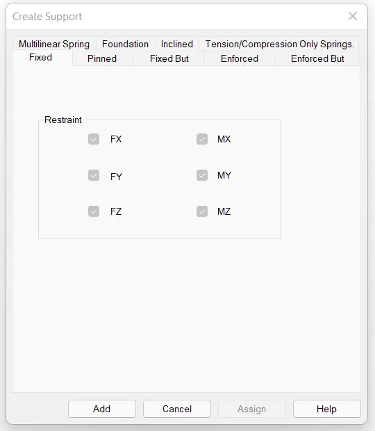
Fixed support: fixed support can carry moment, vertical And horizontal reactions, the DOF in fixed support is 0
Pinned support: pinned support can only support vertical and horizontal reactions, DOF in pinned support is 1
Fixed But: type of support is specified, for those degrees of freedom which are to be treated as fully restrained with some displacements
ENFORCED or ENFORCED BUT type of support is specified, for those degrees of freedom that are to be treated as restrained, STAAD assigns a spring with a very high spring stiffness - translational stiff springs for translational restraints, and rotational stiff springs for rotational restraints
create the nodes for the going slab and landing slab
- After creating the nodes for the going slab and landing slab assign the plates to the slabs either clockwise or anti-clockwise
- Goto properties and assign the properties for plate thickness
- Generate the mesh for the plate as quadrilateral meshing and generate it.
- Apply the loads and perform the analysis
- After the analysis, part defines the design parameters for design and run the analysis
- Go to --> Results --> plate results --> Diagram dialog box ---> Plate stress contour --> select the load case for the combination and stress type as maximum absolute ---> click to apply to view the stress contours for the staircase slab.
The different ways to view the SFD and BMD in STAAD Pro software have been discussed below:
- In order to view the SFD and BMD in the software, first create the model using the nodes method in the geometry panel.
- After creating the nodes, go to the Properties panel and assign the properties to the model.
- And after that give the specification to the model according to the architectural layout.
- Assign the support conditions, after assigning the support condition to the model do the analysis.
- After completing the analysis successfully, now go to the post-processing mode.
- Then there will be another dialogue box, in that dialogue box there will be an option called beam result just click on that option.
- After clicking the option a tool palette will appear on the screen.
- Here we can see different values such as Shear force or the Bending moments.
- So in order to see the shear force diagram, click on the Fy option and if we want to see the bending moment diagram then click on the option Mz.
- So this is the procedure by which we can see the Shear force and Bending moment diagram easily.
Practical
1.
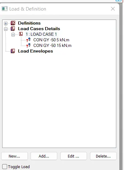
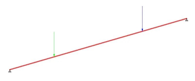
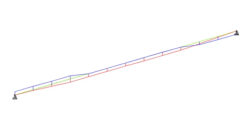
a. To create a 20m with two-point loads
Procedure:
- Create a geometry for a beam of span 20m as shown below
- Create support specifications that satisfy the SS condition using fixed but condition
As for SS condition we need to restrain Fx and Fy alone and of roller support, we want to restrain Fy on the other end as shown above image
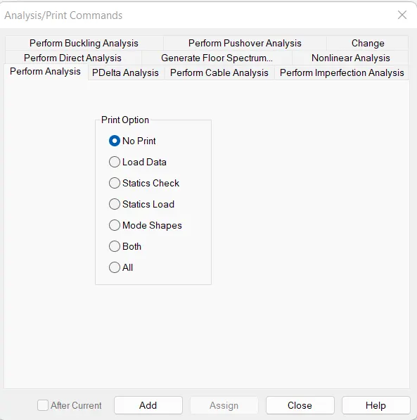
- Analyze the beam by adding perform analysis command
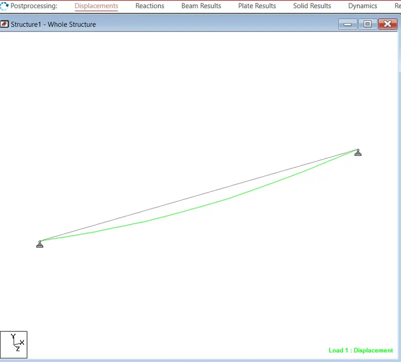
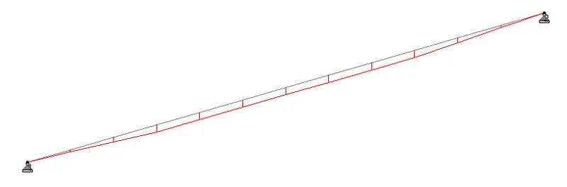
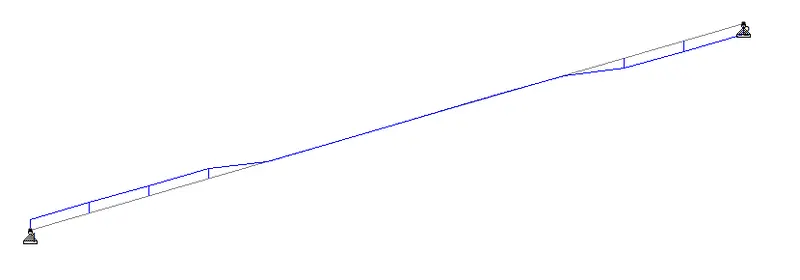
- Now we can see the SF and BM from the beam results from the post-processing results
BMD
SFD
b.
- First of all, draw the beam of length 16m. And to draw the beam of 16m using the node-by-node option.
- After creating the nodes now draw the beams just as shown in the below-given image:
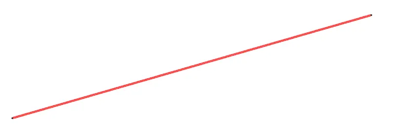
- After creating the beam of 16m length now add the properties to the slab.
- Add a rectangular section to the beam just as shown in the below-given image:
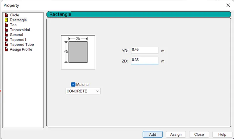
- Now click on the Add option and select the added section and choose the option assign to the view and then click on the option Assign and click just as shown in the below-given image:
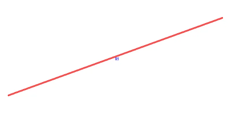
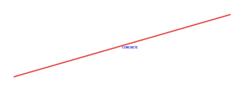
- Now after assigning the property, now we will be assigning the material as Concrete.
- In order to assign the material go to the material panel and then there will be another dialogue box in that dialogue box choose the desired material and assign it to the beam just as shown in the below-given image:
- After assigning the material, now we have to assign the support conditions to the beam, both ends are fixed.
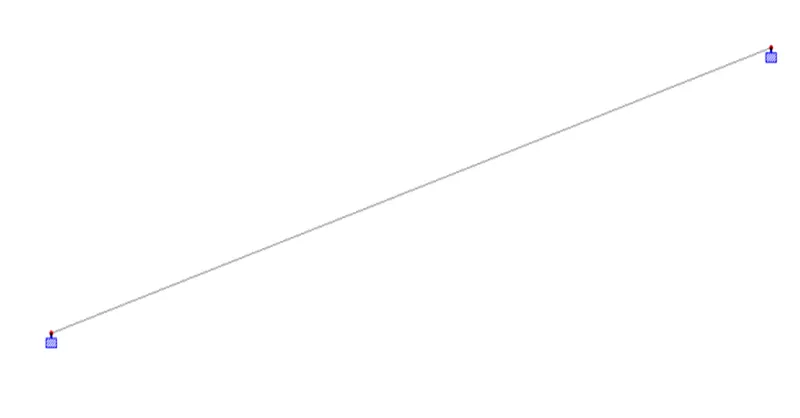
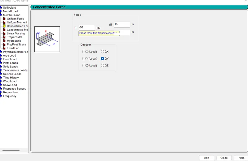
- And now assign the point load of 9 KN just as shown in the below given image:
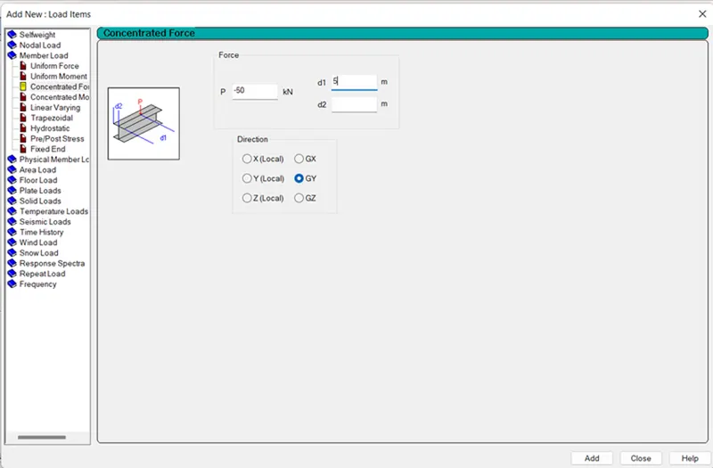
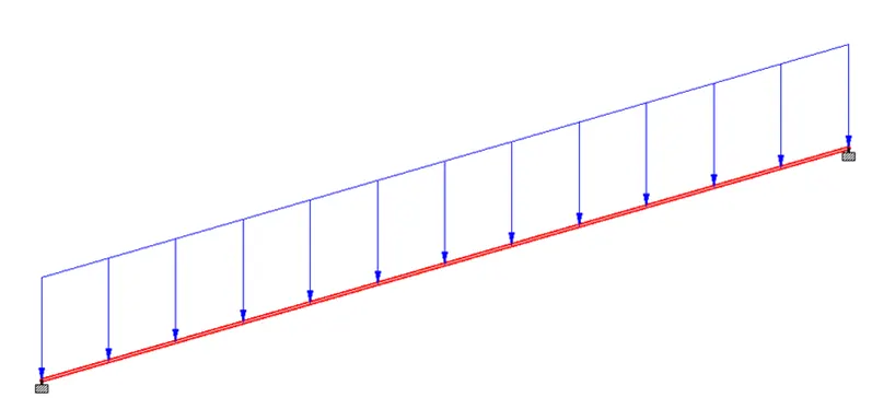
- Now the UDL of 9 KN have been assigned at beam just as shown in the below given image:
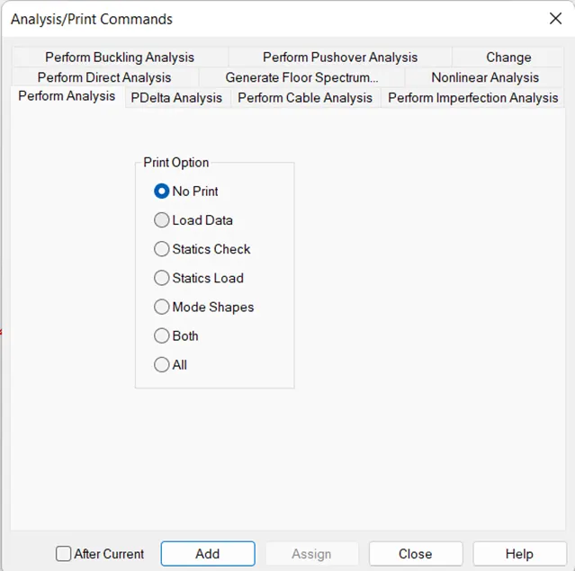
- After assigning the loads we will be doing the analysis, in order to run the analysis set the analysis method and run the analysis just as shown in the below given image:
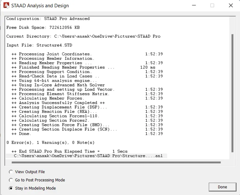
- The analysis has been done:
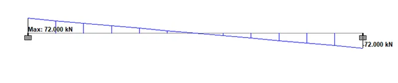
- After doing the analysis go to the post-processing mode and select the load cases and check the SFD & BMD diagrams just as shown in the below given image:
SHEAR FORCE DIAGRAM:
BENDING MOMENT DIAGRAM: