Drafting of various geometries using Chamfer, Fillet tool in AutoCad
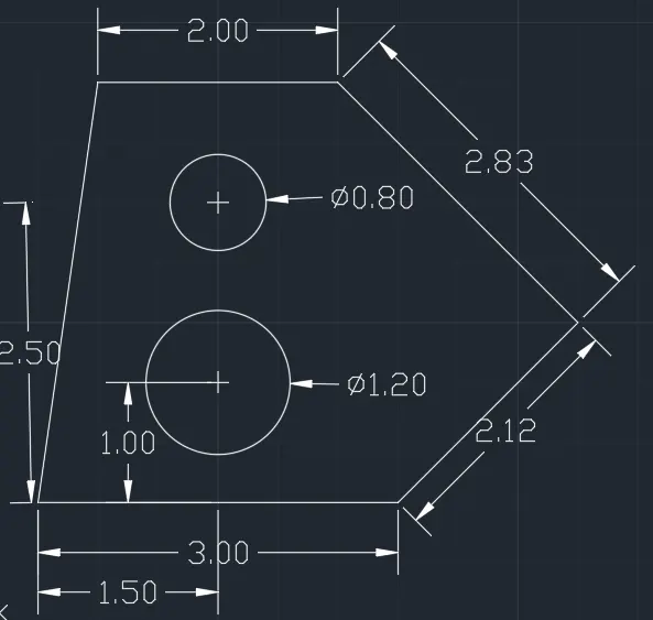
1. Aim: To draw the given drawings by using AutoCAD.
Procedure:
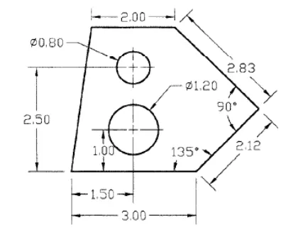
- In the command box type units and select decimal unit.
- In the command box type line
- In the command box specify first point as 1,1
- In the command box type @3<0
- In the command box type @2.12<45
- In the command box type @2.83<135
- In the command box type @2<180
- In the command box type close.
- In the command box type line
- In the command box type specify first point as 1,1
- In the command box type @1.5<0 (line 1)
- In the command box type @1<90(line 2)
- In the command box type circle and select center and diameter.
- In the command box specify the point 2.5,2
- In the command box Radius of 1.2
- And delete the line 1&2
- In the command box type line
- In the command box type specify first point as 1,1
- In the command box type @1.5<0 (line 1)
- In the command box type @2.5<90(line 2)
- In the command box type circle and select center and diameter.
- In the command box specify the point 2.5,3.5
- In the command box Radius of 0.8
- And delete the line 1&2
- enter
Result:
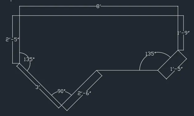
2. Aim: To draw the given drawings by using AutoCAD.
Procedure:
- In the command box type units-type-Architectural-precision- 0'-0"
- Select polar tracking is 45-90-135-180
- In the command box type line
- specify the first anywhere
- In the command box type @2'-6"<225
- In the command box type @3'<135
- In the command box type @2'-5"<90
- In the command box type @8'<0
- In the command box type @1'-9"<270
- In the command box type @1'-5"<225
- In the command box type close
Result:
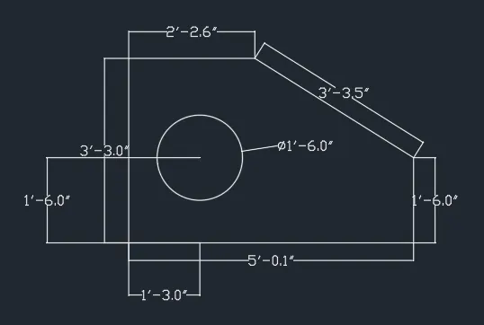
3.Aim: To draw the given drawings by using AutoCAD.
Procedure:
- In the command box type units-type-Engineering-precesion- 0'-0"
- Select polar tracking is 90-180-270-360
- In the command box type line
- specify the first anywhere
- In the command box type @1'-6.0"<270 (A)
- In the command box type @5'-0.1<180 (B)
- In the command box type @3'-3.0"<90 (C)
- In the command box type @2'-2.6"<0 (D)
- In the command box type close (E)
- In the command box type line
- specify the first point at C
- In the command box type @1'-3.0"<0 (line 1)
- In the command box type @1'-6.0"<90 (line 2) (F)
- In the command box type circle of center and radius
- specify point at F
- draw the circle dia as 1'-6.0"
- delete line 1&2
Result:
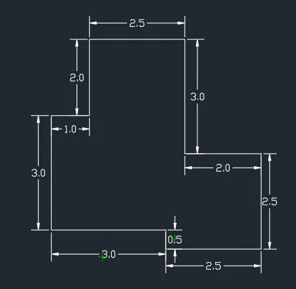
4.Aim: To draw the given drawings by using AutoCAD.
Procedure:
- In the command box type units-type-decimal-precision- 0.00
- In the command box type line
- specify the first anywhere
- In the command box type @2<0
- In the command box type @2.5<270
- In the command box type @2.5<180
- In the command box type @0.5<90
- In the command box type @3<180
- In the command box type @3<90
- In the command box type @1<0
- In the command box type @2<90
- In the command box type @2.5<0
- In the command box type close
Result:
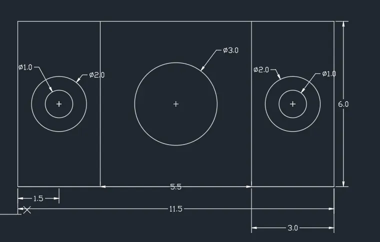
5. Aim: To draw the given drawings by using AutoCAD.
Procedure:
- In the command box type units-type-decimal-precision- 0.00
- In the command box type line
- specify the first point as 1,1
- In the command box type @11.5<0
- In the command box type @6<90
- In the command box type @11.5<180
- In the command box type close
- In the command box line
- Specify the point as 4,1
- In the command box type @6<90
- In the command box type line
- specify the point as 8.5,1
- In the command box type @6<90
- In the command box type circle
- specify the point at center of the left rectangle
- Draw the two circles of dia as 1 and 2
- In the command box type circle
- specify the point at center of the right rectangle
- Draw the two circles of dia as 1 and 2
- In the command box type circle
- specify the point at center of middle rectangle
- Draw the two circles of dia as 3
Result:
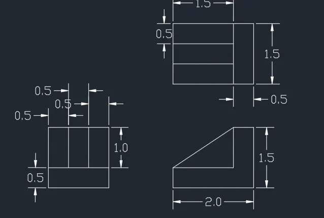
6. Aim: To draw the given drawings by using AutoCAD.
Procedure:
- In the command box type units-type-decimal-precision-0.00
- First draw the left side rectangle.
- In the command box type line
- specify the first point anywhere
- In the command box type @1.5<0
- In the command box type @1.5<90
- In the command box type @1.5<180
- In the command box type @1.5<270
- In the command box type offset
- In the command box type distance 0.5
- With the help of offset get the horizontal line as 0.5
- With the help of offset get 2 vertical lines as 0.5
- Enter
- draw the right top side rectangle.
- In the command box type line
- specify the first point anywhere
- In the command box type @2<0
- In the command box type @1.5<90
- In the command box type @25<180
- In the command box type @1.5<270
- In the command box type offset
- In the command box type distance 0.5
- With the help of offset get 2 horizontal lines as 0.5
- With the help of offset get the vertical line as 0.5
- Enter
- Draw the middle right side
- In the command box type line
- specify the first point at the exact right top side rectangle
- In the command box type @2<0
- In the command box type @1.5<90
- In the command box type @0.5<180
- In the command box type @1<270
- In the command box type @1.5<180
- In the command box type @0.5<270
- In the command box type line
- join the top to lines
- enter
Result:
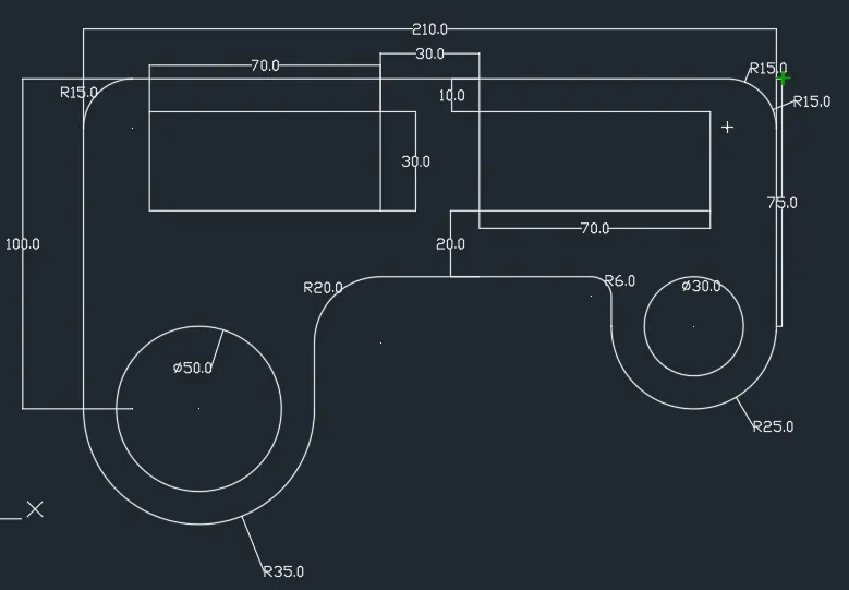
7. Aim: To draw the given drawings by using AutoCAD.
Procedure:
- In the command box type units-type-decimal-precision-0.00.
- In the command box type line
- specify the first point keep anywhere
- In the command box type @100<90 (Point A)
- In the command box type @210<0 (B)
- In the command box type @75<270(C)
- In the command box type line
- Specify the first point at point A
- In the command box type @70<0 (line 1)
- In the command box type @40<90 (D)
- In the command box type @15<270 (E)
- In the command box type @50<0 (line 2)
- In the command box type circle
- select center and diameter 50 at the midpoint of line 1
- In the command box type arc and select start, center, length
- In the command box type select point start at a center to the midpoint of line1
- In the command box type arc length is 70
- In the command box type circle
- select center and diameter 30 at the midpoint of line 2
- In the command box type arc and select start, center, length
- In the command box type select point start at a center to the midpoint of line2
- In the command box type arc length is 50
- delete line 1&2
- In the command box type line
- In the command box type first point at A
- In the command box type @20<0 (Line 3)
- In the command box type @10<270 (line 4)
- In the command box type @70<0
- In the command box type @30<270
- In the command box type @70<180
- In the command box type @30<90
- Delete line 3&4
- In the command box type line
- In the command box type first point at B
- In the command box type @10<270 (line 5)
- In the command box type @20<180 (line 6)
- In the command box type @70<180
- In the command box type @30<270
- In the command box type @70<0
- In the command box type @30<90
- Delete lines 5&6.
- In the command box type fillet
- In the command box type of radius is 15
- In the command box type select lines at point A&B
- In the command box type fillet
- In the command box type of radius is 20
- In the command box type select lines at point D
- In the command box type fillet
- In the command box type of radius as 6
- In the command box type select lines at point E
Result:
8. Aim: To draw the given drawings by using AutoCAD.
Procedure:
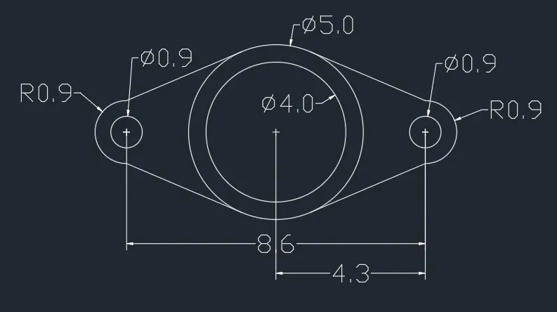
- In the command box type units-type-decimal-precision-0.000
- In the command box type line
- specify the first point keep anywhere
- In the command box type distance as 8.55
- In the command box type circle
- In the command box type select as center and diameter
- In the command box type draw the circle at both the end of the line.
- In the command box type diameter as 0.9
- In the command box type circle
- In the command box type select as center and radius
- In the command box type draw the circle at both the end of the line.
- In the command box type radius of 0.9
- In the command box type circle
- In the command box type select as center and diameter
- In the command box type draw the 2 circles at the midpoint of the line.
- In the command box type diameter as 4&5
- in object snap on the tangent.
- Draw tangent lines through the end circles to the center circle.
Result:
9. Aim: To draw the given drawings by using AutoCAD.
Procedure:
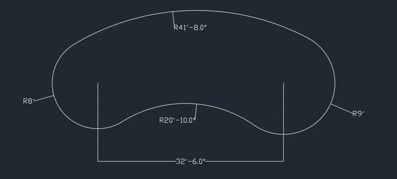
- In the command box type units-type-engineering-precision-0.000
- In the command box type line
- specify the first point keep anywhere
- In the command box type distance as 32'-6"
- In the command box type circle
- In the command box type select as center and diameter
- In the command box type draw the circle at left side of the line.
- In the command box type diameter as 8'
- In the command box type circle
- In the command box type select as center and radius
- In the command box type draw the circle at the right side of the line.
- In the command box type radius of 9'
- In the command box type circle
- In the command box type select as center and radius
- In the command box type draw the circle at the both sides of the line.
- In the command box type radius of left side is 33'-8" and right side is 32'*8"
- Now these two circle bisect at bottom
- In the command box type circle
- In the command box type select as center and radius
- In the command box type draw the circle at a point the bottom bisect of the circles.
- In the command box type radius of 41'-8"
- Now trim the unwanted lines.
- Now at the both of line.
- In the command box type circle.
- In the command box type select as tangent,tangent and radius.
- select the two circles as tangent.
- In the command box type radius of 20'-10"
- and trim the cruve.
- enter
Result:
10. Aim: To draw the given drawings by using AutoCAD.
Procedure:
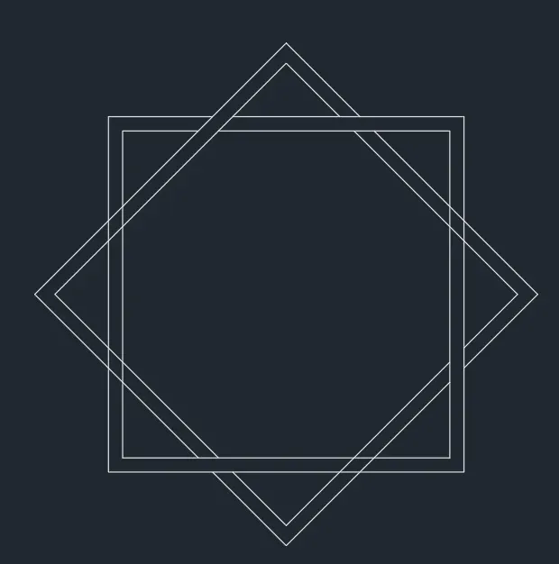
- In the command box type units-type-decimal-precision-0.000
- In the command box type rectangle
- In the command box type rec size is 5*5
- In the command box type rotate the rectangle to diman shape.
- In the command box type offset of some distance.
- anw trim the unwanted lines.
Result:
11. Aim: To draw the given drawings by using AutoCAD.
Procedure:
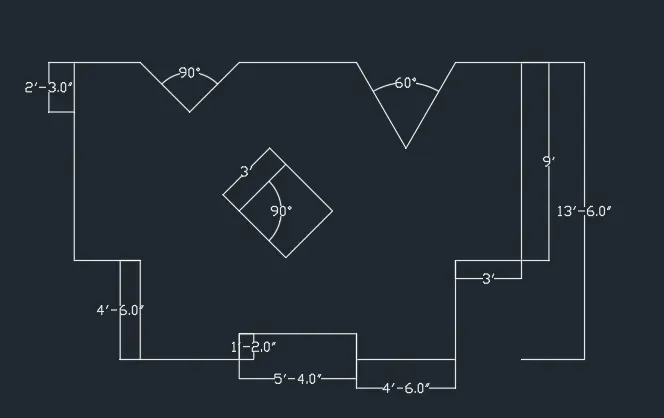
- In the command box type units-type-engineering-precision-0.000
- In the command box type line
- specify the first point keep anywhere
- In the command box type @9'<270
- In the command box type @3'<0
- In the command box type @4'-6"<270
- In the command box type @4'-6"<0
- In the command box type @1'-2"<90
- In the command box type @5'-4"<0
- In the command box type @1'-2"<270
- In the command box type @4'-6"<0
- In the command box type @4'-6"<90
- In the command box type @3'<0
- In the command box type @9'<90
- In the command box type @3'<180
- In the command box type @3'-7"<270 (line 1)
- In the command box type @4'-6"<180 (line 2)
- In the command box type @3'-7"<90 (line 3)
- Draw a two lines from the midpoint of line 2
- And join the two lines to line 1&3
- Delete line 1,2&3
- In the command box type line
- In the command box type @5'-4"<180 (line 4)
- In the command box type @2'-8"<270 (line 5)
- In the command box type @4'-6"<180 (line 6)
- Draw a two lines from the midpoint of line 5
- And join the two lines to line 4&6
- Delete line 4,5&6
- In the command box type line
- specify line at first point
- In the command box type @6'-9"<270
- In the command box type @7'-6"<0 (A)
- In the command box type rectangle
- specify at the point A
- And rec size is 3*3 of angle is 45
- Enter.
Result: