Week 2 Challenge
1.1, Ans:
- Assign circular section to column,
- In properties tab select the Define button Create beam or column.
- In the define we have to select the circular section and give Diameter for the column and Assign material type as concrete.
1.2, Ans:
- Unit system to .std model file.
- To assign units GO to VIEW menu and select Setting.
- Select Unit setting where we can change setting.
1.3, Ans:
- Parameter to be specified using in Bay frame option,
- Length , breadth and width are the parameters are specified in Stuctural wizard to Bay frame option.
- It is avaliable in geometry Tab.
- Click frame model on the bay frame.
- And specify parameters.
1.4, Ans:
- Codal standard incorprated with STAAD PRo.
- For Load we have IS 875 part 1 & 2
- For Steel IS 800 - 2007
- For Concrete IS 456 - 2000
- For Sesmic IS 1893 - 2016 , 13920 - 2016
- For Wind IS 875 Part 3.
1.5, Ans:
- Design compressive strength of RCC member,
- In general goto Define and define parameter
- Click the button and in the tab select FC and include value
- Select Fy and include the value.
2.1, Ans:
- Steps Involved in RC designs,
- Geometry : Node location and node detail are given
- Load defination : Load cases are define and assign the value.
- Property : To define the material type of the structure .
- Design standard : Define all data like compressive strength, Fck ,Fy min and max steel requirement etc as per IS 456 -2000
- Design parameters commands : There are some command lines and select design of column or beam type.
- Analysis : Select the analysis type.
2.2, Ans:
- Fixed support:
- In this type of support are 3 force and 3 moments are avaliable and then executed.
- For Enforced Support :
- The all supports are fixed with 3 force and 3 moments with certain negilance we can add or remove the force and moment which is required.
3.1, Ans:
- Steps involved in Analysis of model using STAAD PRO,
- Run Analysis from the Analysis Ribbon
- Then Analysis command click add performance analysis
- Then Run the Analysis once again the result will be done.
3.2, Ans:
- The 2 ways where structural model or frame can be made using STAAD PRO,
- BY Using Node
- Here we can assign nodes value by adding nodes in it then create beam or column model .
- By Using BAY Frame
- In this method we can add direct what kind of work we are going to do we can add frame , truss, etc.
3.3, Ans:
- Differen support condition in STAAD PRO
- FIXED
- All Transitional and rotation are fixed
- FIXED BUT.
- All are fixed but we can add are remove the transitional force in it.
- PINNED
- Three Transitional are fixed but rotaion are free to move.
- ENFORCED
- It is same as fixed all are fixed.
- ENFORCED BUT
- Here all are free to move with certain execuption
- INCLINED
- Here restiction at joints only rotaion are free.
3.4, Ans:
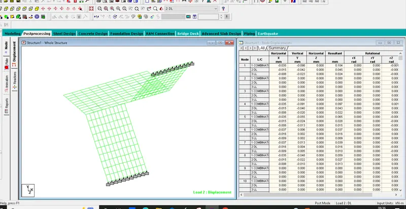
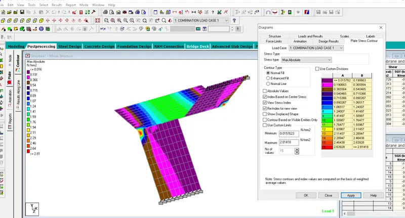
- Extract the stress distribution for a staircase slab,
3.1.5, Ans:
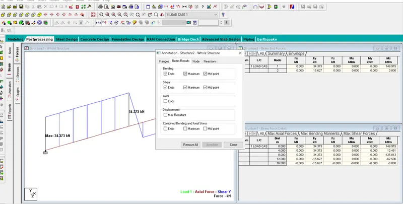
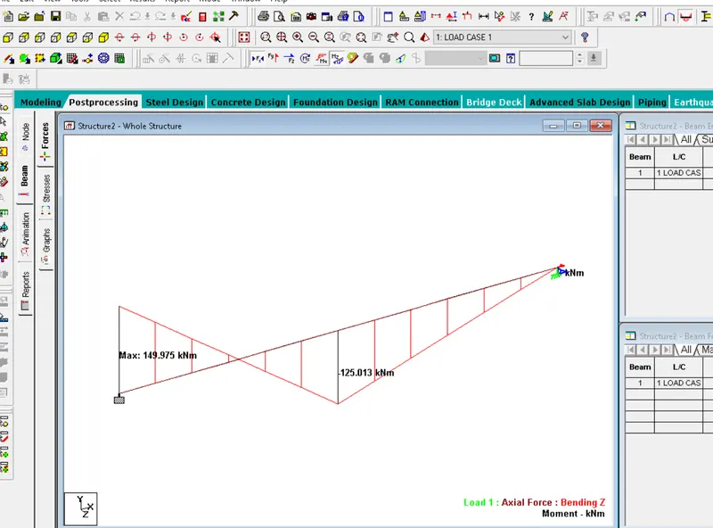
- Different views to view Bending moment and Shear stress,
- Once the analysis is done we can get in to result tab and select view value and we can get annotation diolag box
- There we can get the BM and SF value.
- In the Above ribbon tab there will be short cut to open SF and BM to view the value.
PRACTICALS :
A. Simply Supported Beam
a. A Simply supported beam with two point loads symmetrically placed
b. Span L = 20m
c. Load P = 50kN each
d. Both P located at 5m from each support
PROCEDURE :
- Create a Model using plane open STAAD PRO.
- Once the Model is created then go to Geometry click NODe and give the points (0,0,0) and (16,0,0)
- The two nodes are created then Click ADD BEAM option from Point to point.
- Draw the beam Once created Assign material property Clicking Define and add the beam size with rectangular or circular.
- Once created assign the beam property concrete click the selected beam radio button and assign the property.
- Then go to support and assign PINNED support and assign using click on crusor and apply it.
- The click Load and Definition then click the load case details and add load Dead load and ADD self weight of - 1 kn /m
- Then ADD load LIVE LOAD and ADD POINT LOAD on node then assign -50 kn/m.
- Then create load combination with Dead load and Live load of combination 1.5
- Assing the value to loads to the beam then analysis and print the option then click ok.
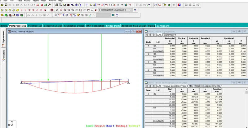
B.Fixed Beam
a. Span L = 16m
b. Uniformly Distributed Load w=9kN/m
PROCEDURE :
- Create a Model using plane open STAAD PRO.
- Once the Model is created then go to Geometry click NODe and give the points (0,0,0) and (16,0,0)
- The two nodes are created then Click ADD BEAM option from Point to point.
- Draw the beam Once created Assign material property Clicking Define and add the beam size with rectangular or circular.
- Once created assign the beam property concrete click the selected beam radio button and assign the property.
- Then go to support and assign PINNED support and assign using click on crusor and apply it.
- The click Load and Definition then click the load case details and add load Dead load and ADD self weight of - 1 kn /m
- Then ADD load LIVE LOAD and Uniform distrubtion load 9 kn/m.
- Then create load combination with Dead load and Live load of combination 1.5
- Assing the value to loads to the beam then analysis and print the option then click ok.
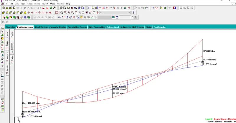
- Hence Proved.