Week 2 Challenge
Que 1. -
1. 1. How will you assign the Circular section to the column?
ANS -
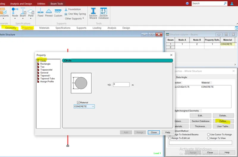
To Assign a circular section to the column. click on the column and after that select geometry or select a property. when we open a there is opening a browser in the right side. in that section there is a option is define click on that and it is allowed to define a section. click on circuler and after that provide a dia.
2. How will you assign Unit system to a .std model file?
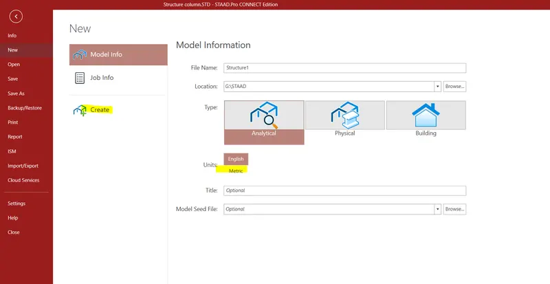
ANS - UNIT SYSTEM - To assign the unit system to the. std file. when we open a staad pro in first orientation page there is a model information page in that page we can set up unit system.
3. What are the parameters to be specified while using “Bay Frame” option?
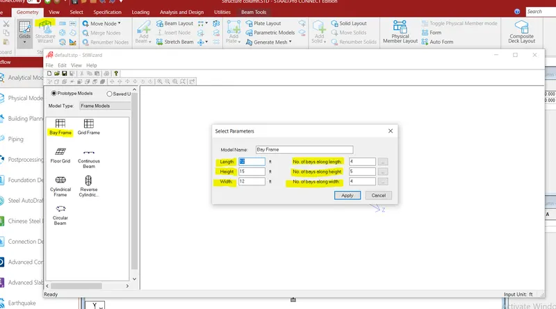
ANS - the following three parameters are specified while using bay frame option.
1. length
2. height
3. width
along with this there is a option for how many numbers u provide along with height length and width. for bays.
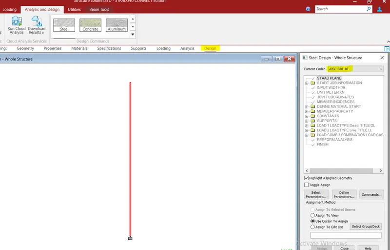
4. Name few codal standards incorporated in STAAD Pro software.
ANS - IN the Disgine option there is a more than 20 codal provisions incorporated in the software. which we used to design the object.
1. IS 456 - for rcc design
2. IS 800 - 2007 FOR STEEL DESIGN.
3. IS 432 FOR MILD STEEL
4. IS 1893 - 2016 FOR BUILDING DESIGN
ALONG THIS AISC, BSS SP ALSO AVAILABLE IN STAAD PRO SOFTWARE AND USE TO DESIGN THE MODEL.
5. How will you specify the design compressive strength for a RCC section?
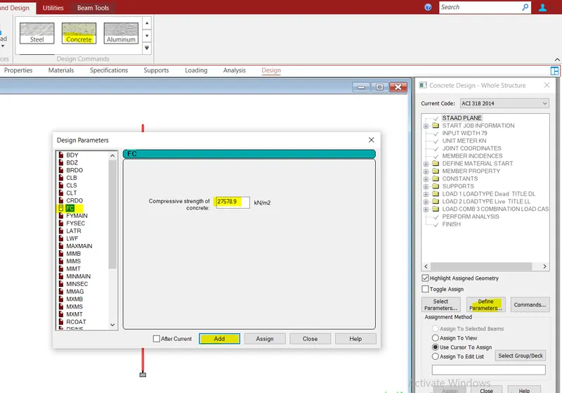
ANS - Specifying design compressive strength for an Rcc Section - to define compressive strength for a RCC section. click on design option in staad pro after that select a concrete in beam tool. after that select define parameters. after that click on Fc and it opens a compressive strength concrete in that putting the value of the compressive strength of a rcc sction.
QUE . 2
1. State the “Input” steps involved in RCC design.
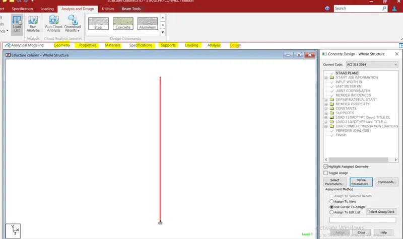
ANS - The following steps were use to design a rcc design.
1. geometry
2. properties.
3. specification.
4. supports
5. loading
6. analysis
7. design
after clicking on the prototype and after doing the analysis.
2. Explain the difference between Fixed and Enforced support conditions in STAADPro.
ANS - FIXED SUPPORTS -
when the fixed type of support is specified. for that degree of freedom which are to be treated as fully restrained. staad assumes the displacements to be known quantities whose value is zero. hence that degree of freedom are not considered for the stiffness matrix. and their value is not calculated.
Enforced type of support -
this suport is specified. for that degree of freedom which is to be treated as restrained. staad assign a spring with a spring stiffness translation spring stiff spring for translational restraints and rotational stiff spring for rotational restraints those degrees of freedom which are free to displace are assigned springs are of zero stiffness. hence all the 6 degrees of freedom at such supports the displacement calculated. the ones which have a spring stiff spring will end up having a negligible displacement based on the structure goemetry propertiies and loadings.
QUE .3
1. Explain the steps involved in the analysis of a model using STAAD Pro sequentially.
ANS -
The following steps were use to analysis of the model using staad pro.
1. geometry
2. properties.
3. specification.
4. supports
5. loading
6. analysis
7. design
after clicking on the prototype and after doing the analysis.
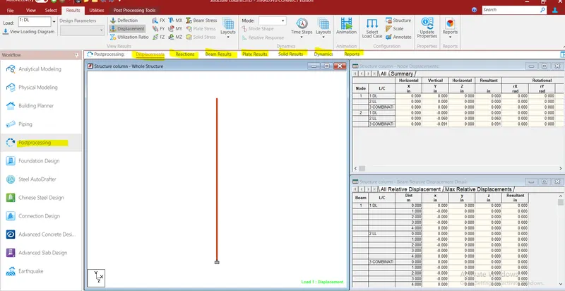
after completing this all the above steps click on the postprocessing option and analysis the model.
after that the window will show the different result who related to the model.
1. displacement
2. reactions
3. beam result
4. plate result
5. solid result
6. dynamic
7. result.
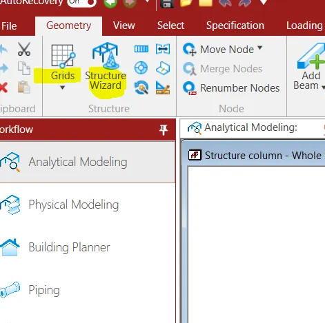
2. Explain the two ways in which a structural framework/model can be created in STAAD Pro software.
ANS - The foloowing two ways in which structural model are creating using staad pro.
1. by grid
2. structure wizard
3. Elaborate the different support conditions in STAAD Pro.
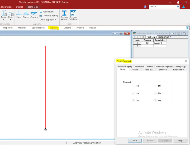
ANS -
For assign support to the model click on support and after that. create a support and it will open window to define various supports.
4. How will you extract the stress distribution for a staircase slab?
ANS - The following steps were use to define stress distribution of the staircase.
1. create the respective nodes of a stair slab
2. Assign plate element as slab property
3. define load cases and calculate the area load acting on to the stair slab
4. apply the load cases and combinations to the plate element as area load
5. mesh plate element.
6. go for the analysis and go for thr post-processing mode
7. select plate result plate stress contour
8. under the stress type choose the appropriate stress type
5. Explain the different ways to view SFD & BMD in STAAD Pro.
ANS -
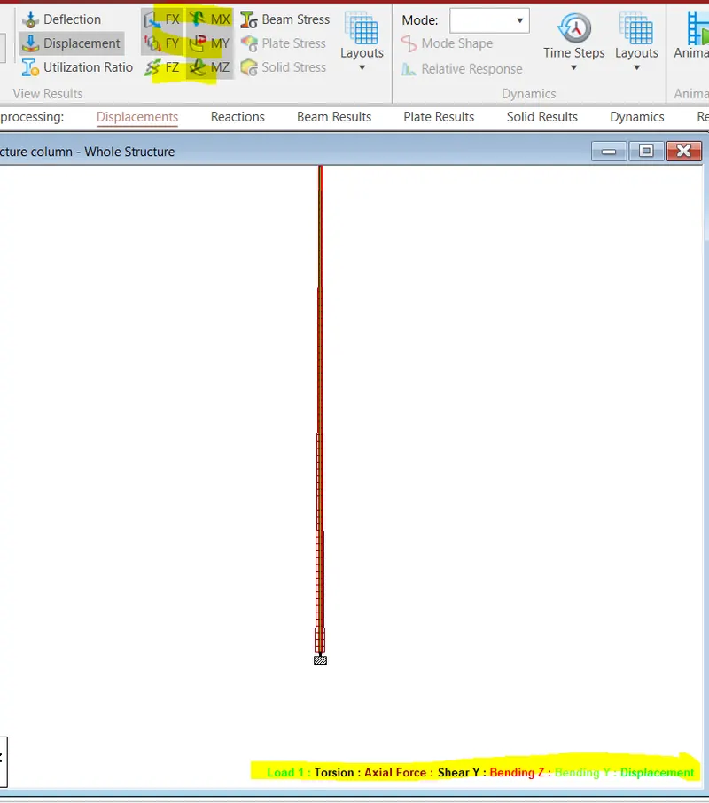
TO VIEW SFD and BMD click on post processing mode in that mode select annotate option in that option select select the beam result for bending and moment
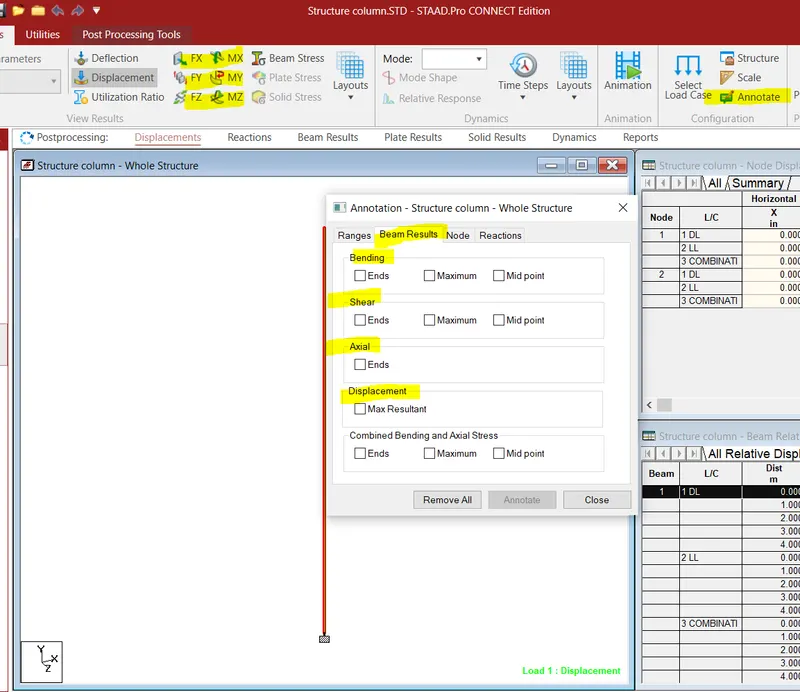
for saw the graphical representation click on fx mx my fy fz mz.
PRACTICAL -
1. Analyze the following structural elements and validate the results
A. Simply Supported Beam
a. A Simply supported beam with two point loads symmetrically placed
b. Span L = 20m
c. Load P = 50kN each
d. Both P located at 5m from each support
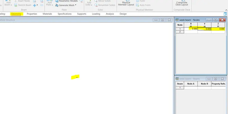
ANS - to create a simply supported beam tick on the create a node providing a 0 meter leangth in x,y, and z direction.
after that
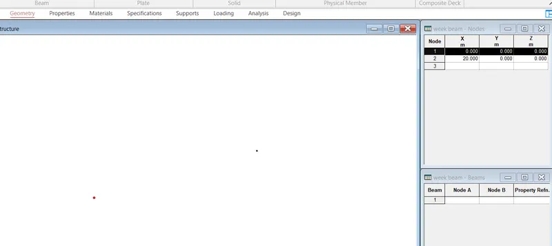
after that selecting a created node and copying it in x direction and provide 20m. length to the node.
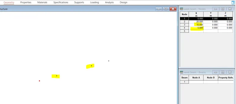
to assign point load 5m. from both the end. selecting a node cursor and in right side provide -5m. and left side provide 5m. node to the point.
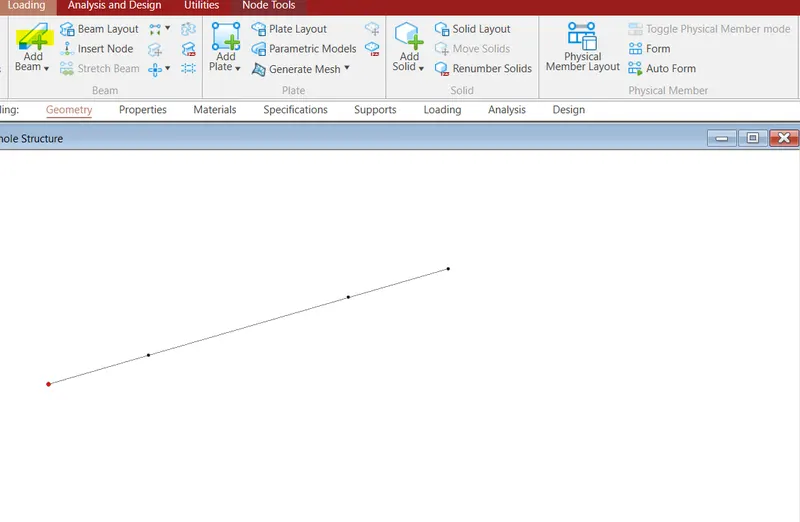
after. select a beam cursor and create a beam having 20m. length.
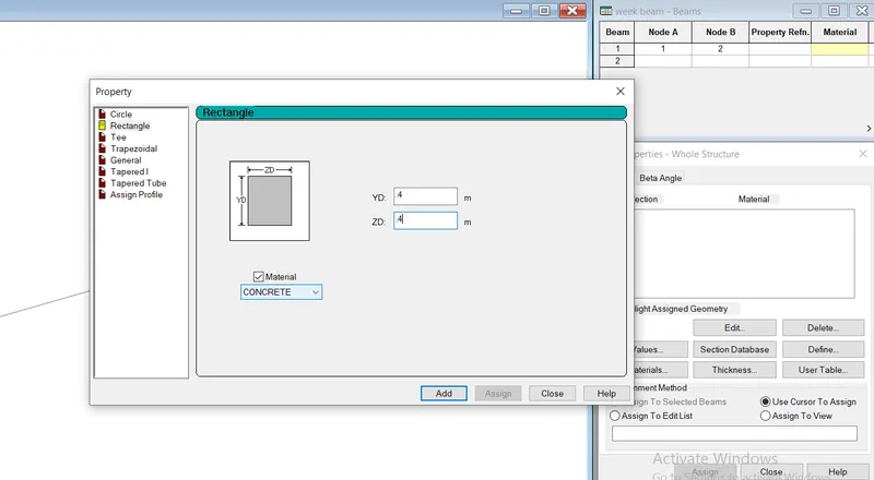
Property - in property defining a rectangular section and provide .4x.4 m size
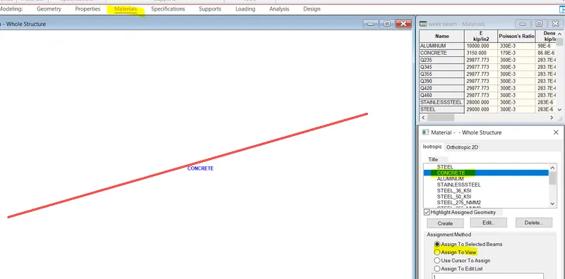
Material - in material select a concrete and after that select assign to view.
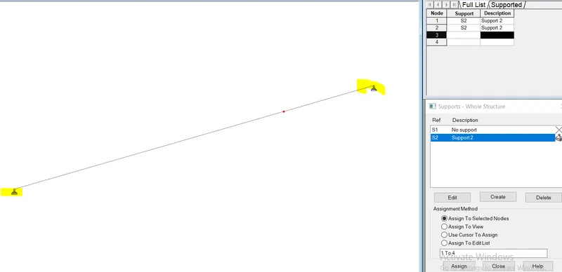
Support - Assign pinned support to the both end.
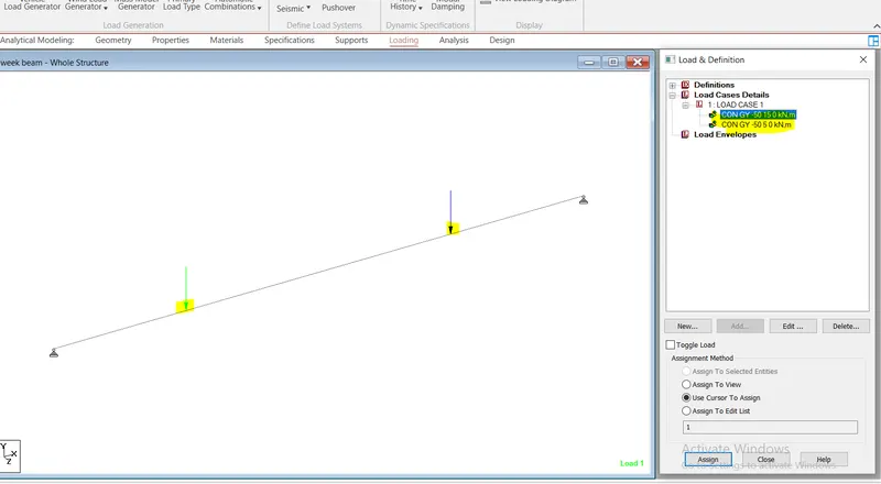
assign point load -
assigning point load of 50kn to both ends. from 5 meters according to quetion. on created nodes which is 5m. from d2 and 15m. from d2
B.Fixed Beam
a. Span L = 16m
b. Uniformly Distributed Load w=9kN/m
ANS -
Geometry - to create a geometry defining a node and copying with 16m. distance
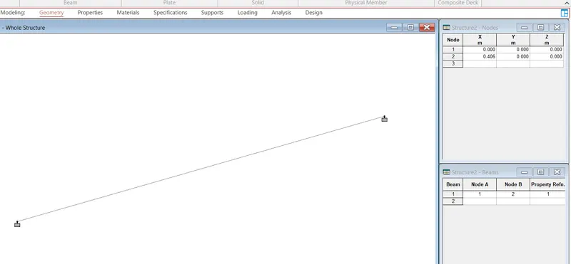
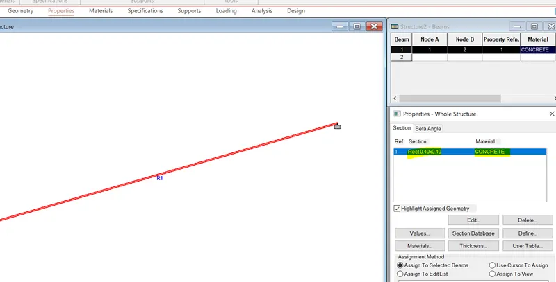
property - providing concrete property and section of .4x.4 m.
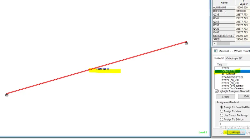
Material - providing material as a concrete.
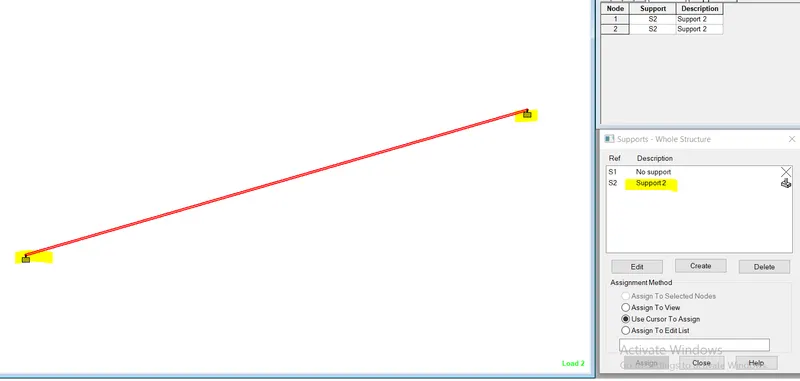
suports - define fixed supports at both the end and assigne it.
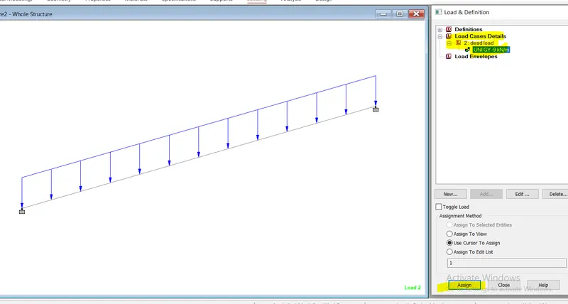
Loadings - in loading create a load casses as a dead load and create udl load about 9 kn. and assign it to the structure.