Creation of geometries by Coordinate system methods using AutoCad
QUE 1
p1 ans
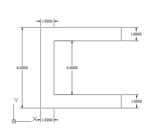
use relative coordinate method for drawing object.
the following points we use to draw and first pont is shoeing the X direction and another point showethe Y DIRECTION.
1. SPECIFYING FIRST POINT WHICH ONE (2,1)
2. @(6,0)
3.@ (0,1)
4. @ (-5,0)
5. @ (4,0)
6. @ ( 0,1)
7. @ (-5,0)
8 . 2 (-1,0)
9. AFTER THAT END POINT ARE CLODE WITH START POINT
THIS ALL POINS ARE USE TO DRAW p1 object.
QUE 2 DRAW P2 OBJECT.
ANS -
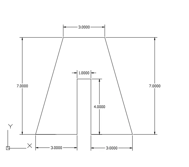
THE FOLLOWING STEPS ARE USE TO DRAW P2 OBJECT .
1. SPECIFYING FIRST POINT WHICH IS (2,1)
2. @3,0
3. @ 0,4
4. @ 1,0
5. @ 0,-4
6. @ 3,0
7. @ -2,7
8. @ -3,0
9. 2 -2,-7
THIS ALL RELATIVE COORDINATE ARE USE TO DRAW P2 OBJECT.
QUE 3 OBJECT P4.
ANS -
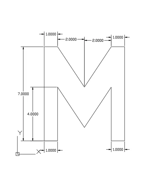
THE FOLLOWING STEPS ARE USE TO DRAW P4 OBJECT.
1. Specifying first point (2,1)
2. @ 1,0
3. @0,4
4. @ 2,-3
5. @ 2,3
6. @ 0,-4
7. @ 1,0
8. @ 0,7
9. @ -1,0
10. @ 0,7
11. @ -1,0
12. @ -2,-3
13. @ -2,3
14. @ -1,0
15. close to start point of the object .
QUE 4 - DRAWING OBJECT P5
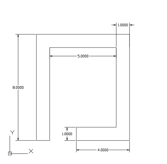
THE FOLLOEING P5 OBJECT DRAW BY THE METHOD OF RELATIVE COORDINATE METHOD .
THE FOLLOWING STEPS INVOLVE IN P5 OBJECT.
1. specifying first point is 2,1
2. @ 1,0
3. @ 0,7
4. @ 5,0
5. @ 0,-6
6. @-3,0
7. @ 0,-1
8. @ 4,0
9. @ 0,8
10. @ -7,0
and close to the start poit of the object.
que 5 drawing p7 object
ans - 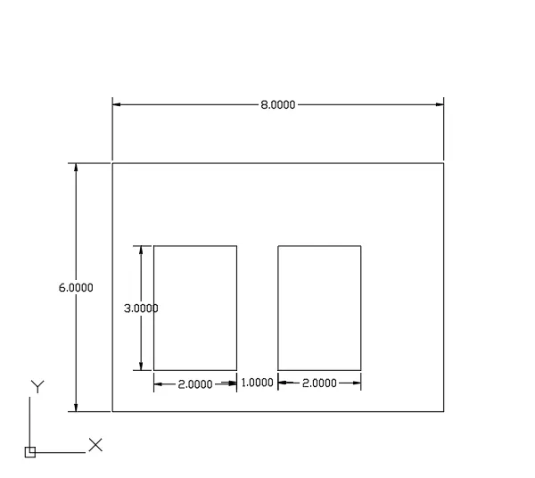
the following steps are use to draw p7 object
1. specifying first point 2,1
2. @ 0,6
3. @ 8,0
4. @ 0,-6
5. after closing the rectangle and pick another line to draw inside recangle,
6. start origine is create by absolute coodinate method and use 3,2 to specify start point of the object.
7. next point is @ 2,0
8. @ 0,3
9. @ -2,0
10. close the inside rectangkle to the start point.
11. for create another rectangle need to start another line to start new origine the origine is. 6,2
12. after @ 2,0
13. @ 0,3
14. @ -2,0
and close to the start point and we obtaind a p7 object.
que 6 -
ans drawing object p8 with relative coordinate syestemand start point are design by absolute coordinate syestem.
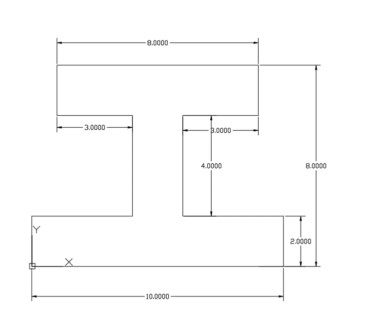
the foloeing steps are useto draw p8 object
1. 1. specify first point is 0,0
2. @10,0
3. @0,2
3. @-4,0
4. 20,4
5. @3,0
6. @0,2
7. @-8,0
8. @0,-2
9. @3,0
10. @0,-4
11. @ -4,0
and close to start point.
QUE 7. DRAW P-9 OBJECT.
ANS - DRAWING OP-9 OJECT WITH RELATIVE CORDINATE SYESTEM .
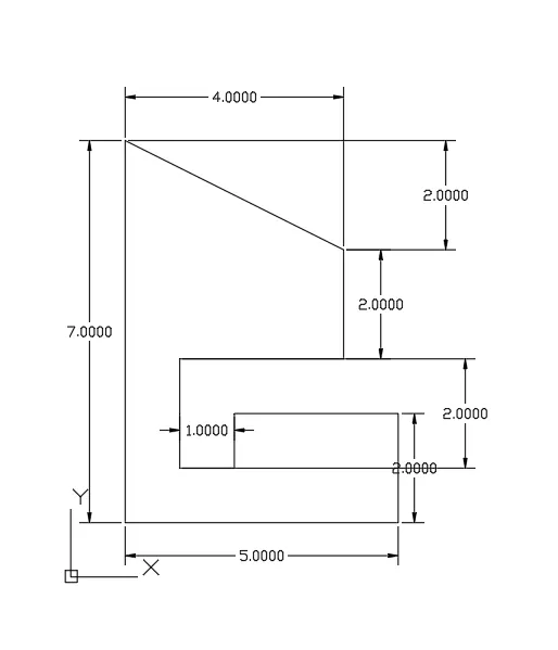
THE FOLLOWING OBJECT DRAW BY RELATIVE COORDINATE SYESTEM.
SPECIFYING ALL STEPS
1. SPEICIFY FIRSTPOINT FROM ORIGIN IS 1,1
2. @5,0
3. @ 0,2
4. @-3,0
5. @0,-1
6. @ -1,0
7. @ 0,2
8. @ 3,0
9. @0,2
10. @ 3,0
11. @ 0,2
12. @-4,2
13 CLOSE TO THE START POINT.
que 8 - draw callenge p - 10
ans - 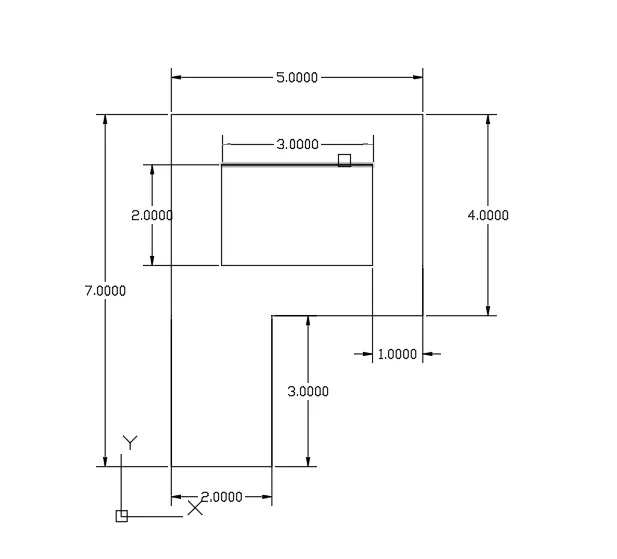
the following p- 10 object draw by using relative coordinate syestem
specifying all steps
1. @ 2,0
2. @ 0,3
3. @ 3,0
4. @ 0,4
5. @-5,0
6. close to start point for inside rectangular we use absolute cordinate syestem to draw rectangle.
7. origin 2,5
8. @3,0
9. @0,2
10. @-3,0
11. @ close to start point .
it is the steps we use to draw p- 10.
QUE 9 -
ANS -
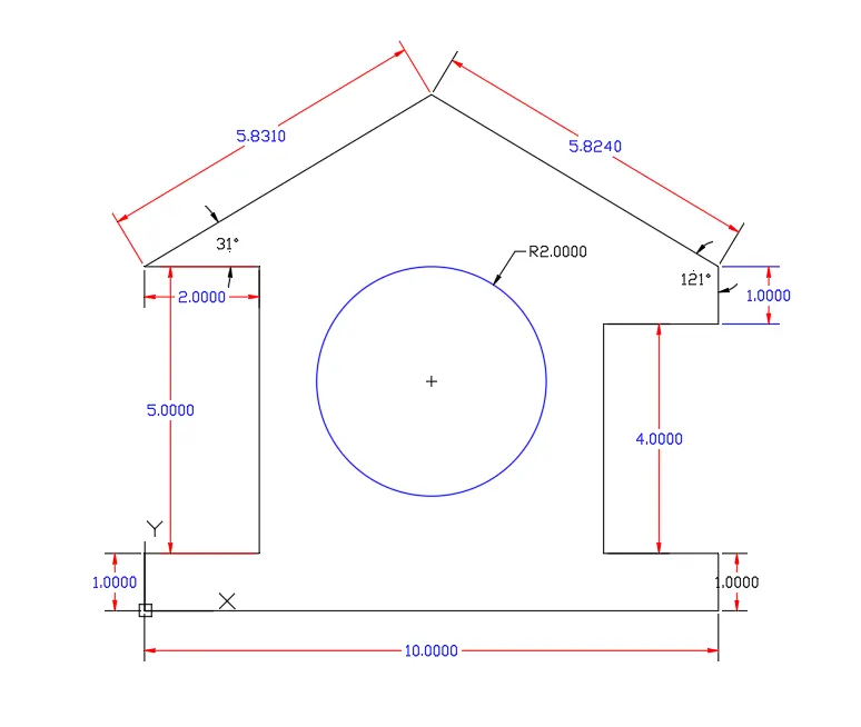
the following steps are use to draw p-10 pbject.
1. specify first point 0,0
2. @10,0
3. @0,1
4. @-2,0
5. @0,4
6. @2,0
7. @0,1
8. @-5,3
9. @-5,-3
10. @2,0
11. @0,-5
12. @-2,0
closed to the end point.
13. CREATE CIRCLE USING 5,4 FROM ABSOLUTE COORDINATE SYESTEM. AND USE RADIUS IS 2 UNIT.
QUE 10. DRAW A QUEEN POST TRUSS.
ANS. - IN DAIGRAM THE UPER ANGLE IS WRONG IS WRONG NEED TO DRAW 45 ANGLE IN THE QUEEN TRUSS DIAGRAMME.
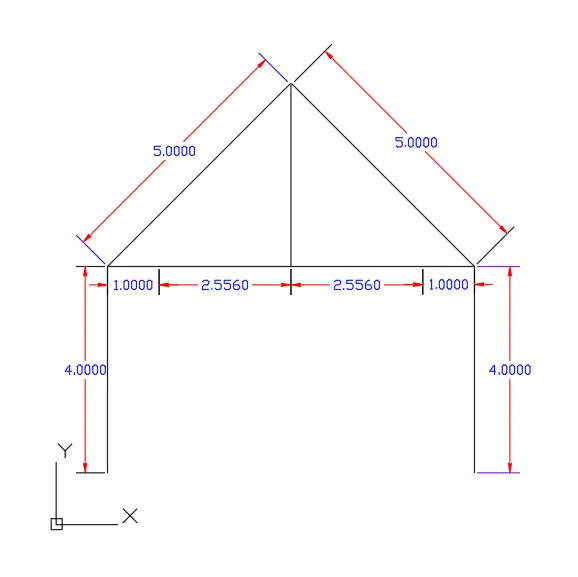
THE FOLLWING POINTS WERE USE IN HE DRAWING QUEEN TRUSS OBJECT.
IN THIS OBJECT 65 ANGLE IS NO CORRECT TO PROVIDE LEANGTH. IN 65 ANGLE WE USE 45 ANGLE TO DRAW OBJECT.
1. specifying first point 1,1
2. @1,4
3. @1,0
4. @2.556,0
5. @2.556,0
6. @1,0
7. @0,-4
8. corner point we use 45 and draw @5,45
9. and other corner we use @5,45. and create a queen truss.
que 11. design a mono pitch
ans.
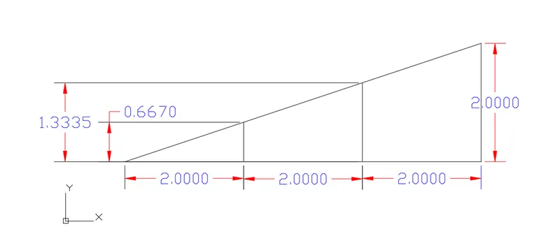
the following points were use to mono pitch.
1. specifying point first 1,1
2. @2,0
3. @2,0
4. @2,0
5. @0,2 upward
6. start slope from start point
7. @0.667,2
it is the whole procces to create mono pitch.