Week 2 Challenge
Q. 1)
1) Ans -
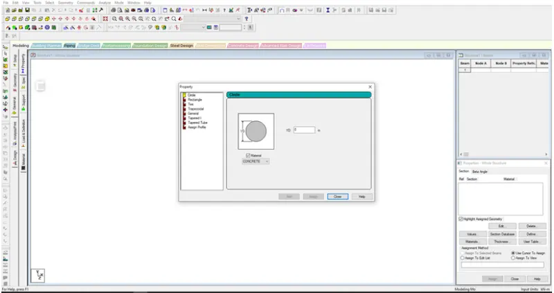
- Select the member
- Go to properties tab
- Click on Define
- Select circle
2) Ans -
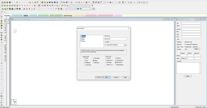
To assign unit system in the stadd pro -
- Go to File menu and then setting
- Open the structural settings
- Change the dimensions
3) Ans -
- Length of the model
- Height of the model
- Width of the model
- No of bays along length
- No of bays along height
- No of bays along width
4) Ans -
- IS 456-2000
- IS 13920-2016
- IS 800-2007
- IS 875-1987
- IS 1893-2016
5) Ans -
- Go to design tab
- Select concrete
- Click on define parameter
- Click on FC and input the compressive strength of the concrete
Q.2)
1) Ans -
- To create Geometry
- Assign Properties
- Specifications
- Assign Support
- Assign Load and load combinations
- Design standards
- Run the analysis
- Checks result
2) Ans -
When the Fixed type of support is specified,for those degree of freedom which are to be treated as fully Restrained STAAD assumes the displacements to be known quantities whose value is zero.hence those degree of freedom are not considered for the stiffness matrix,are their value is not calculated.
when the Enforced type of support is specified,for those degree of freedom which are to be treated as restrained,STAAD assigns with a spring stiffnes translational stiff springs for translational restraints,and rotational stiff spring for rotational restraints.Those degree of freedom which are free to displace are assigned springs of zero stiffness Hence,for all the 6 degrees of freedom at such supports,the displacement are calculated.The ones which have a stiff spring will end up having a negligible displacement,and those with zero-stiffness springs will have a displacement based on the structure geometry properties and loading.
Q.3)
1) Ans -
Steps involved in analysis of models are -
1) Read/Study drawings
2) Input geometry
3)Input properties
4)Input supports
5) Input load and load combinations
6) Input design standards
7) Specify Analysis Type
8) Run Analysis
9) Verify Results
10) Design
11) Represent design as document and drawing
2) Ans -
Structural model can be created by -
- By entering the coordinates of each node in the grid table
- By using Bay option in prototype models
3) Ans -
- Pinned
- Fixed but
- Enforced
- Enforced but
- Multilinear springs
- Tension/Compression only springs
- Foundation
4) Ans -
- After analysis go to the postprocessing
- Select load combinations
- Click on plate result
- Select plate stess contour
- Select load combinations
- Check Max absolute stress
- Check Major principle stress
- Check MX(Local)
5) Ans -
- After analysis
- Go to post processing
- Check SFD and BMD by click on SFD and BMD tool
- Next click on Layout and click on graph to view SFD and BMD
- By double click on Member
Practical -
A) Ans-
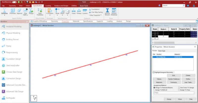
- Open STAAD software
- Create new model
- Select Metric
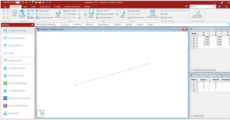
- Go to geometry and give distnace of 0-20 m intable
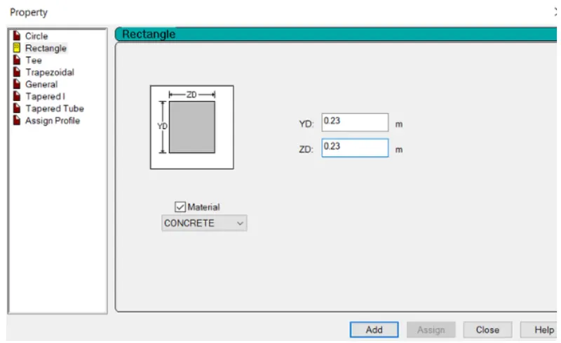
- Go to property and add property of beam
- Choose rectangle and material concrete
- Assign the property to the view.
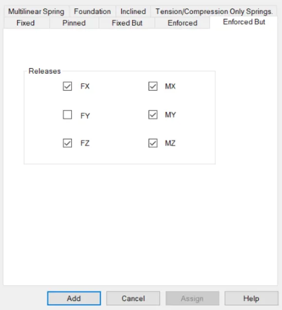
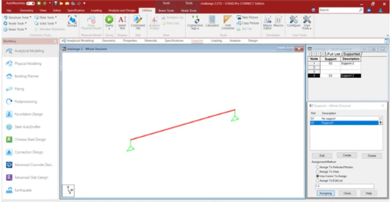
- Go to the support
- Create supports
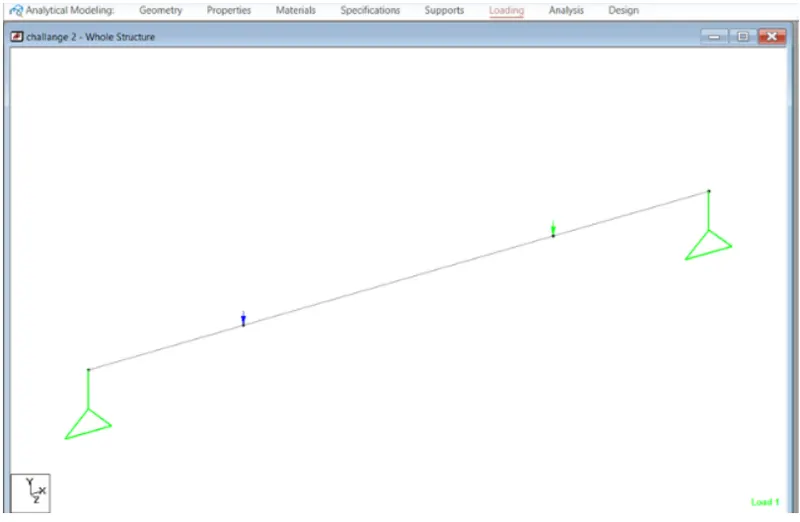
- Create support as simply supported (only Restraint at Fy)
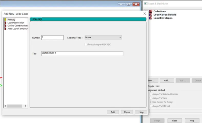
- Go to the loading tab
- Click on load case details
- Add load case
- Add self weight
- Again click on load case
- Click on member load
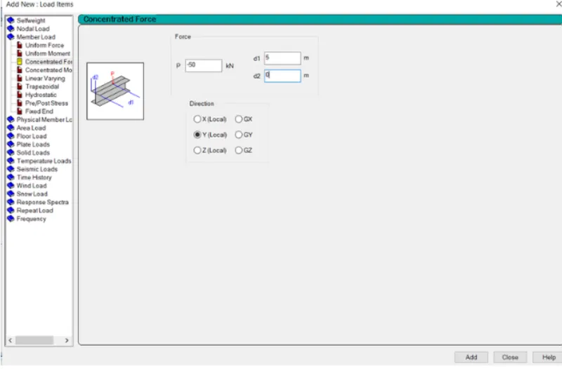
- Add concentrated load of 50 kn at the distance of 5 and 10 m
- Now add the load
- Assign the load to the member
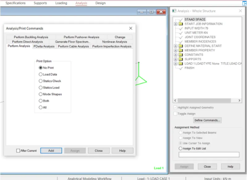
- Now go to Assign gtab
- Click on defiine command and add perform analysis
- After analysis go to postprocessing
- Click on load case
- Check SFD,BMD and Displacement
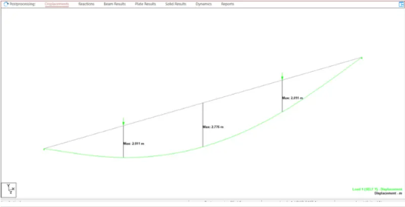
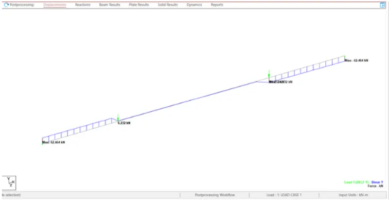
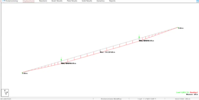
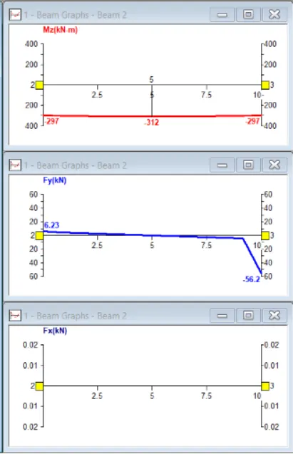
Max BMD = 312 Kn/m
Max SFD = 662 Kn
Max Displacement = 2.776 m
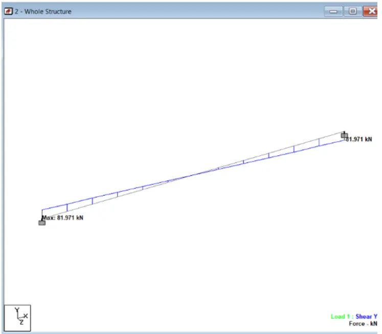
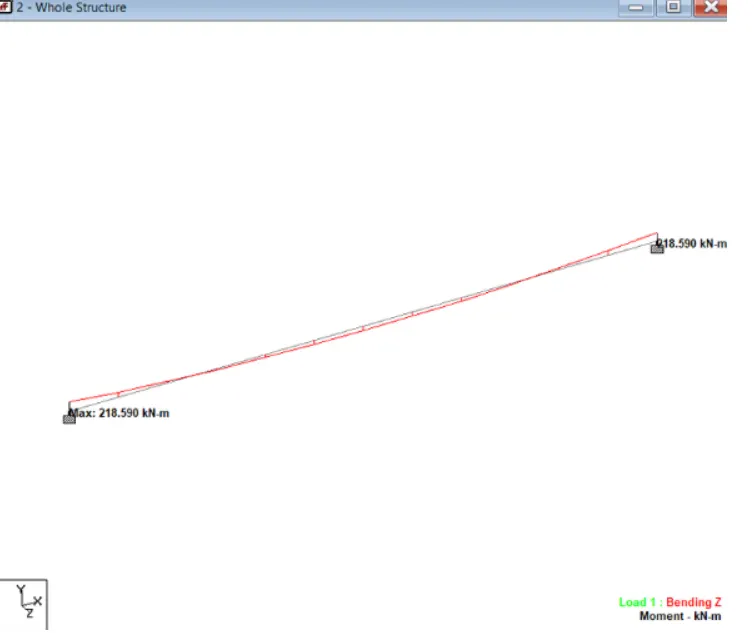
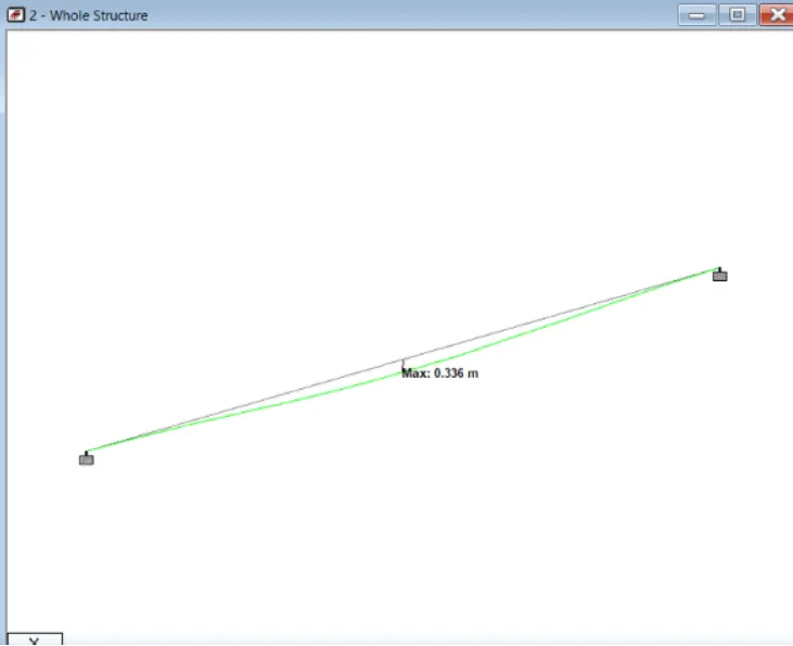
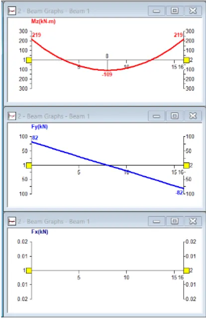
B) Ans-
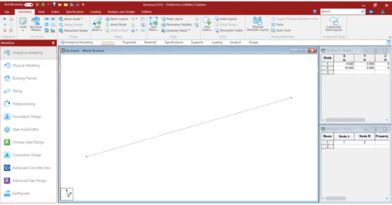
- Go to geometry
- Add length of 16 m in X in table
- Go to property tab
- Add properry as Rectangle and material as concrete
- Assign the property
- Go to support tab
- Add support as Fixed
- assign the support
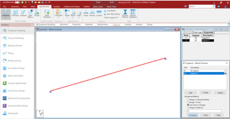
- Go to loading
- Click on laod case
- Add load case
- Add self weight
- Click on menber laod and add uniform load of 9 kn/m
- Assign the load
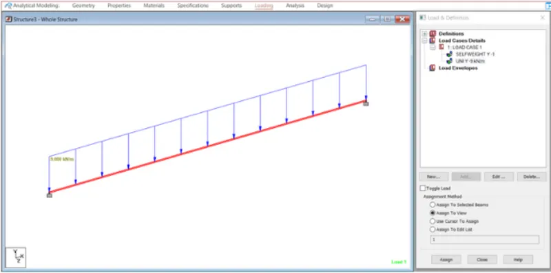
- Now analyse the model
- Click on define command
- Run analysis
- After analysis go to postprocessing
- Add load case
- Check SFD,BMD and displacement