Week 2 Challenge
1
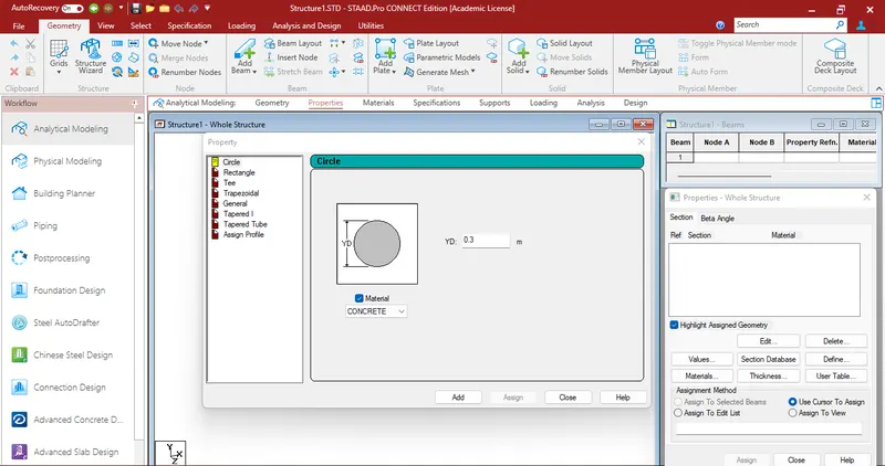
1) Assign Circular section to column :-
* Open the STAAD software.
* Goto properties tab, click on define choose circle then give the dia value.
* Click add and close assign to view.
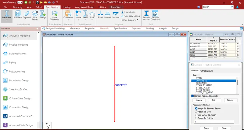
* Goto material tab then select the material and assign property to view.
2) Assign Unit system to a .std model file :-
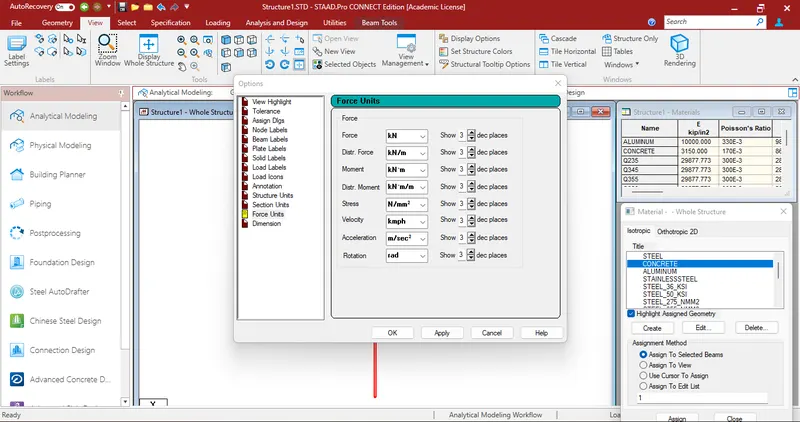
* Open the STAAD software.
* Goto view tab, click on display options then change the units.
* Next click on apply.
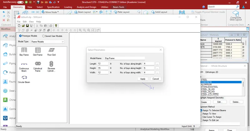
3) The parameters to be specified while using “Bay Frame” option :-
* Length of the model
* Height of the model
* Width of the model
* No of bays along length
* No of bays along height
* No of bays along width
4) Name few codal standards incorporated in STAAD Pro software :-
* IS 456-2000
* IS 13920-2016
* IS 875-1987
* IS 800-2007
* IS 1893-2016
5) Specify the design compressive strength for a RCC section :-
* Open the STAAD software.
* Goto design tab, select concrete click on define parameters.
* In the dialog box, click on FC and give the value.
2
1) The “Input” steps involved in RCC design :-
* Open STAAD software.
* To create geometry
* Assign property
* Assign supports
* Assign loads
* Analyze the models
* Select on design tab
* Select IS code
* Give compressive strength of concrete
* Run the analysis
* Goto postprocessing
* Select beam
* Check the result
2) The difference between Fixed and Enforced support condition in STAADPro :-
| Fixed | Enforced support condition |
| Degrees of freedom which are to be treated as fully restrained, Hence, those degrees of freedom are not considered for the stiffness matrix, and their value is not calculated. | Degrees of freedom which are free to displace are assigned springs of zero stiffness. Hence, for all the 6 degrees of freedom at such supports, the displacements are calculated. |
3
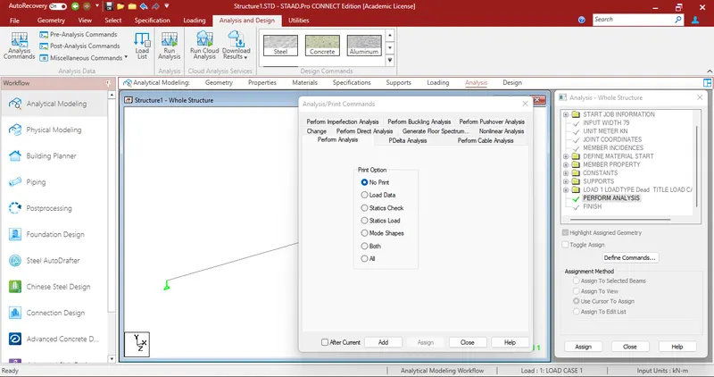
1) The steps involved in analysis of a model using STAAD Pro sequentially :-
* Open STAAD software.
* Go to the Analysis Tab
* Select Define Commands
* A new Window will open
* Click on Performed Analysis
* Click on add and close
* Click on Run Analysis
* Save the File
* Agian Run
* A new window PopUp
* Check any Errors
* Resolve If Any Errors using Commands and Put Plane as space
* Now Again Click on run Analysis
2) The two ways in which a structural framework/model can be created in STAAD Pro software :-
* By analytical model
* By physical model
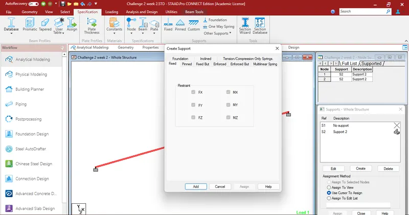
3) The different support conditions in STAAD Pro :-
* Fixed
* pinned
* Fixed but
* Enforced
* Enforced but
* Multilinear spring
* Foundation
* Inclined
* Tension/compression only springs
4) Extract the stress distribution for a staircase slab :-
* Open STAAD software.
* To create geometry
* Assign property
* Assign supports
* Assign loads
* Analyze the models
* Goto postprocessing
* Select load combination
* Click on plate resiults
* Select plate stress contour
* Select load combination
* Check max absolute stress
* Check major principle stress
* Check Mx(local)
5) The different ways to view SFD & BMD in STAAD Pro :-
* Open STAAD software.
* To create geometry
* Assign property
* Assign supports
* Assign loads
* Analyze the models
* Goto postprocessing
* Check SFD and BMD by click on SFD and BMD tool
* Click on layout and click on graph to view SFD and BMD
* By double click on member
Practical :-
A)
Aim :-
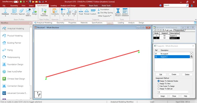
Analyze the following structural elements and validate the results
Simply Supported Beam
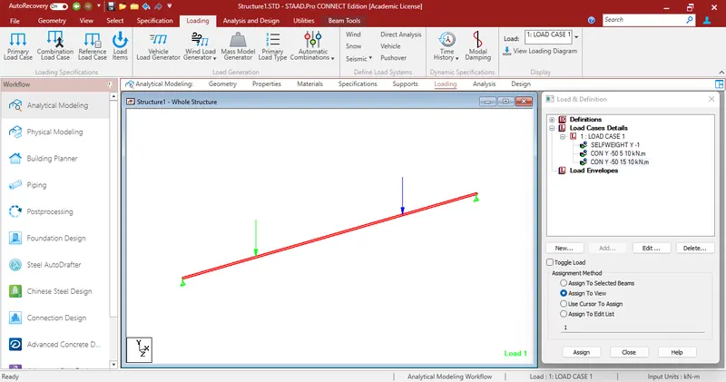
a. A Simply supported beam with two point loads symmetrically placed
b. Span L = 20m
c. Load P = 50kN each
d. Both P located at 5m from each support
Procedure :-
* Open the staad software.
* Units set as m and load as kN.
* In the top dorp down on grids tab, click on beam grid.
* Draw the beam.
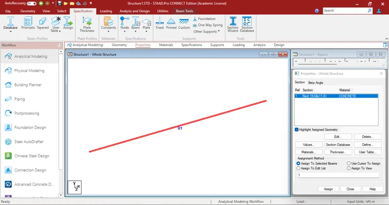
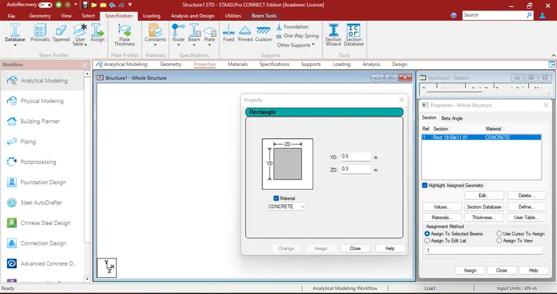
* Goto properties tab, dialog box select define provide the size of beam.
* Goto material tab to assign material.
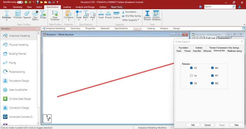
* Goto support tab,click on create then select the supports.
* Finally goto loading tab, dialog box load cases details add load case then edit the load then assign.
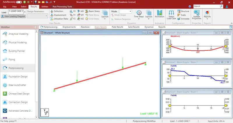
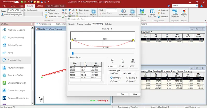
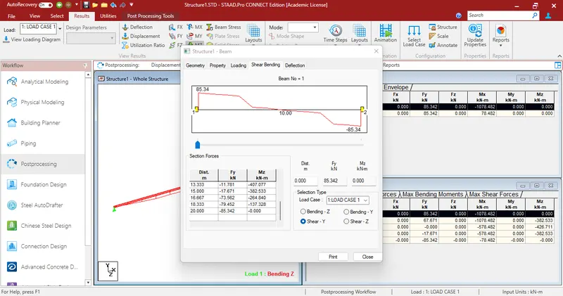
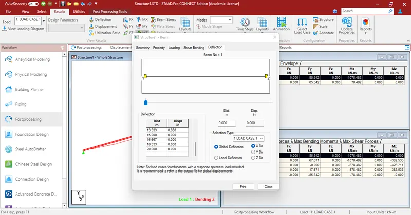
* Finally click on the beam dialog box will be appear select shear bending display the shear and bending moment diagrams.
Result :-
Sucessfully complete analyze the following structural elements and validate the results
Simply Supported Beam
a. A Simply supported beam with two point loads symmetrically placed
b. Span L = 20m
c. Load P = 50kN each
d. Both P located at 5m from each support
Max BMD = 427KN
Max SFD = 85KN
Max Displacement = 2.5KN
B)
Aim :-
Analyze the following structural elements and validate the results
Fixed Beam
a. Span L = 16m
b. Uniformly Distributed Load w=9kN/m
Procedure :-
* Open the staad software.
* Units set as m and load as kN.
* In the top dorp down on grids tab, click on beam grid.
* Draw the beam.
* Goto properties tab, dialog box select define provide the size of beam.
* Goto material tab to assign material.
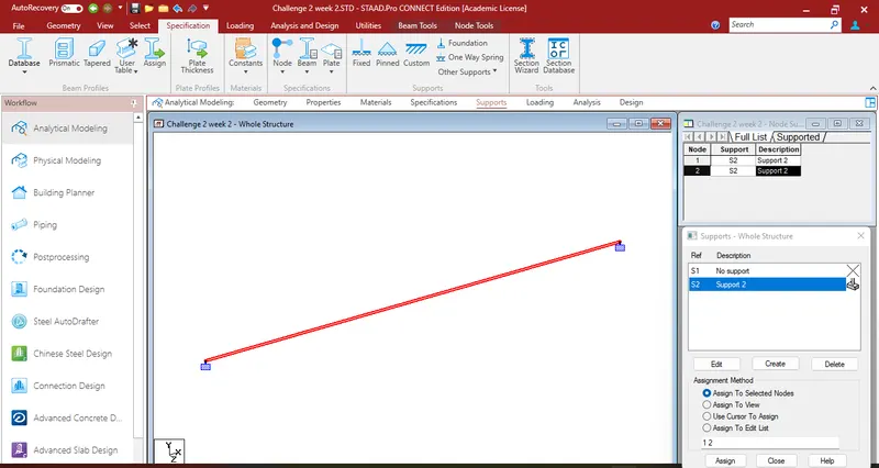
* Goto support tab,click on create then select the supports.
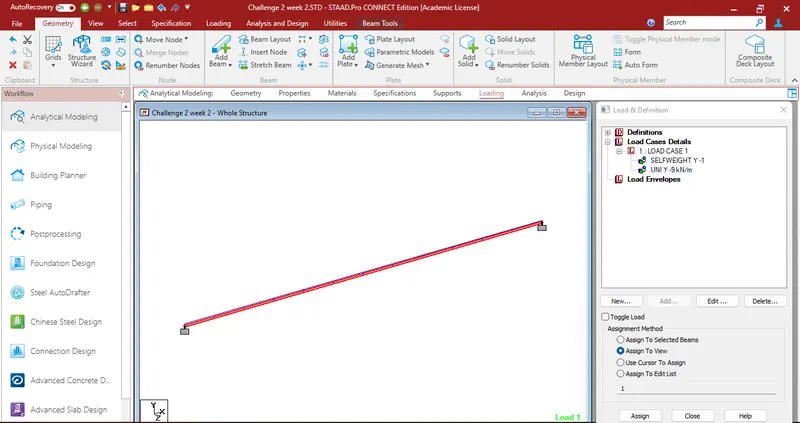
* Finally goto loading tab, dialog box load cases details add load case then edit the load then assign.
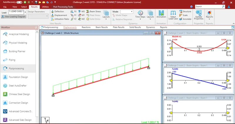
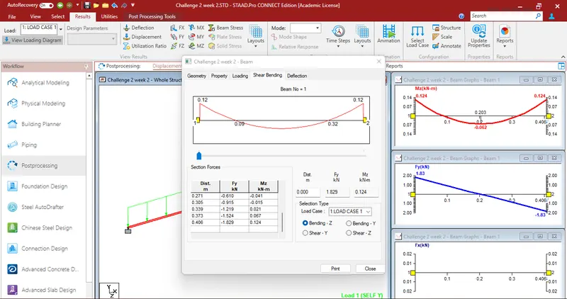
* Finally click on the beam dialog box will be appear select shear bending display the shear and bending moment diagrams.
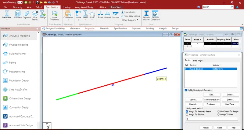
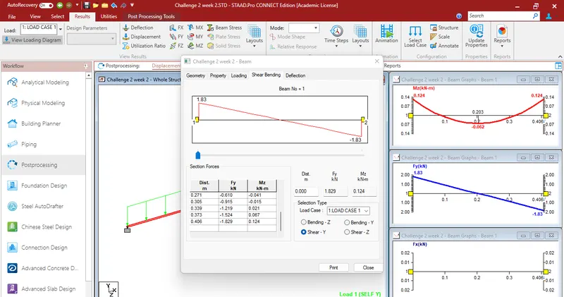
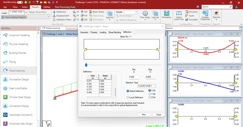
Results :-
Analyze the following structural elements and validate the results
Fixed Beam
a. Span L = 16m
b. Uniformly Distributed Load w=9kN/m
Max BMD = 0.124KN
Max SFD = 1.83KN
Max Displacement = 0.406KN