REVIT_Creation of Basic Drawing_Week2
1)Building Information Modeling (BIM) is a digital representation of physical and functional characteristics of a facility.
A BIM is a shared knowledge resource for information about a facility forming a reliable basis for decisions during its lifecycle; defined as existing from earliest conception to demolition.
BIM covers more than just geometry — it covers “spatial relationships, light analysis, geographic information, and quantities and properties of building components.
The various subsets of BIM are described in terms of dimensions — 3D (object model), 4D (time), 5D (cost), 6D (operation), 7D (sustainability), and even 8D (safety).
Benefits of BIM over 2D CAD tools:
1)Coordination and Collaboration.
2)Conflict detection and Risk Mitigation.
3)High Level of Customisation and Flexibility.
4)Optimization of Schedule and Cost.
5)Easy Maintenance of Building Life Cycle.
6)Faster Drafting without loss of Cost and Quality.
7)Competitiveness
8)Easy access to Information.
7)Competitiveness
8)Easy access to Information.
9)Increase in Efficiency and Productivity.
Advantages of BIM:
There are several advantages of the BIM. Some of them are,
A BIM model will allow you to pre-fabricate important components ahead of time. You won’t have to adjust them based on the building design. Instead such components of are the part of the initial design.
BIM offers a more complete representation of the building’s design. It takes more than the building’s core components into account. For example, BIM allows you to design electrical and HVAC systems, as well as the building itself. This means the project team can make the full advantage of the space and resources available.
BIM pulls documents into a single database. Several people can work on the same model and save it to the cloud. It allows for instant update so you won’t waste the time searching for the documents when you need to make changes.
You can provide much more to your clients in BIM than you could with CAD. The model you give to the clients update constantly as you work on the project. Your client can check in any time, which leads to quicker approval for milestones and more efficient project development.
Resource tracking is key component in BIM model, you’ll can be able to figure out how much resources are required.
2)Categoriesare an import tool within Revit for identifying the inferred type of an element, such as anything in the Walls category should be considered as a wall.
Categories are pre=defined within the software and cannot be added, deleted or renamed.
Families are the collection of like items sharing the same overlook and behaviour.
All elements in the Revit platform are a part of family and they fit into a clearly defined hierarchy.
Revit includes many families such as the “Basic Wall” wall family, the “Single-Flush” door family and many annotation families like “Text” or “Linear Dimension Style.”
Anything in the Revit architecture project is called Element.
Instance Parameter enables us to modify the parameter value separately for every instance.
AIM: To use categories, families, instances and elements.
TOOLS/COMMANDS USED:
Insert
Load Family
Instances
Elements
Categories
PROCEDURE:
Step-1: Go to Revit.
Step-2: Select the insert tool and select the Load Family menu.
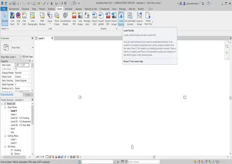
Step-3: A dialog box of categories under families appears.
Step-4: Select an element and select the required instance.
RESULT:
An element is selected from the families.
3)AIM: Setting up a new project and set up the maximum backups to 3.
TOOLS/COMMANDS USED:
File
Save
Manage
PROCEDURE:
Step-1: Open Revit.
Step-2: Open file and choose new and select project.
Step-3: Choose imperial architectural template and click OK.
Step-4: Open the manage tab and select project information.
Step-5: Now a dialog box of project information appears.
Step-6: Fill the details in the project information dialog box.
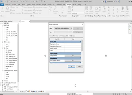
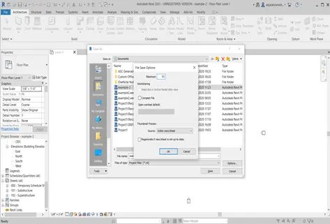
Step-7: Now go the file tab again and click on save as and select project.
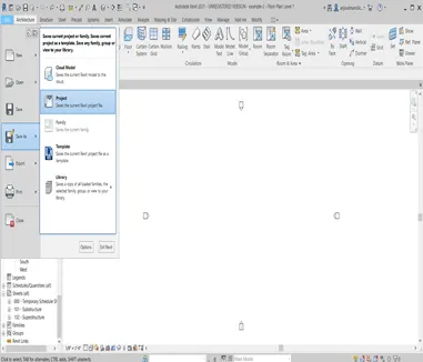
Step-8: Now a dialog box opens, select options.
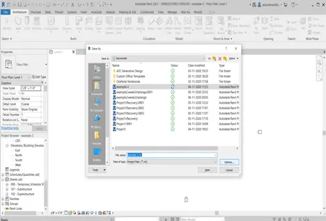
Step-9: Now another dialog box of file save options and change the maximum number to 3.
RESULT:
A project is successfully created and saved. And the maximum backups of the project is set to 3.
4)A) Levels and Gridsare finite planes that help to define project context.
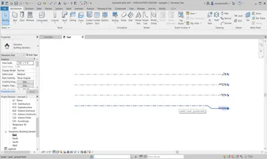
AIM: To create different levels and name them as below,
First Floor @ 10’
Second Floor @ 20’
Roof @ 30’
TOOLS/COMMANDS USED:
Architectural wall
Elevations
Levels
PROCEDURE:
Step-1: Open Revit and select construction template.
Step-2: Go to elevations at the project browser and select east.
Step-3: Now different levels appears on the screen.
Step-4: Make the required changes.
RESULT:
The levels at required measurements are obtained successfully.
B) For transverse grids the naming will be given from bottom to top in an ascending order.
For longitudinal grids the naming will be given from right to left in an ascending order.
Grids can be named either with A, B, C…. Or with 1, 2, 3….
AIM: To form different types of grids.
TOOLS/COMMANDS USED:
Construction template
Grid
Architectural tool bar
PROCEDURE:
Step-1: Open the Revit software and select construction template.
Step-2: Select the architectural tool bar.
Step-3: Now select the grid option at the right corner of the architectural tool panel.
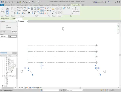
Step-4: Draw five transverse grid lines and name them as A, B, C, D & E of offset 10’.
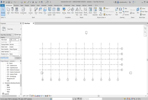
Step-5: Now draw ten longitudinal grid lines and name them 1-10 and of offset 20’.
RESULT:
The grids of required grid lines with given offsets are drawn successfully.
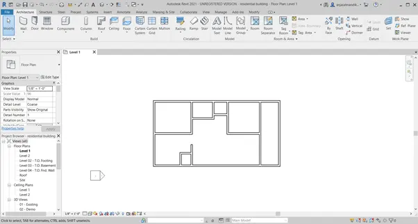
5)AIM: To create a layout of a residential unit.
TOOLS/COMMANDS USED:
Architectural template
Architectural walls
PROCEDURE:
Step-1: Open the Revit software and select the imperial construction template in new tab.
Step-2: Now go to the file tab and save the project name as residential building.
Step-3: Select the wall icon and choose architectural wall.
Step-4: Now place the walls of dimensions 27’-0” X 52’-6”.
RESULT:
A conceptual layout of a residential layout is created successfully.
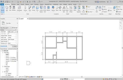
6)AIM: To draft the level of details in the residential layout.
TOOLS/COMMANDS USED:
Annotate tool
Aligned dimension
PROCEDURE:
Step-1: Open the previous residential building project.
Step-2: Measure the dimensions of the walls by using aligned dimension tool.
RESULT:
The dimensions of the rooms in the residential building layout are measured successfully.
7)AIM: To insert the residential building models in the residential building layout.
TOOLS/COMMANDS USED:
Architectural tool bar
Insert tool bar
Load Families
Doors
Windows
PROCEDURE:
Step-1: Go to the previous residential building layout.
Step-2: Select the required doors and windows.
Step-3: Go to insert tool bar and select load families and get the models required for the residential building.
Step-4: Insert the models at their place by place components panel.
Step-5: Change the orientation of the required models by modify tool bar.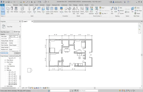
Step-6: Save the project.
RESULT:
The residential building models are inserted successfully in the layout.