Week 2 Challenge
# AIM
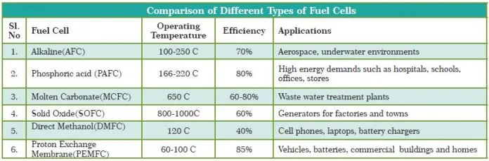
1) Compare four different types of fuel cells and state their applications.
2) Using a plot with energy density and power density on the X and Y axis, arrange various battery types like lithium-ion, lead acid, Nickel Cadmium, Ultracapacitor, and fuel cell.
# EXPLANATION
1) Compare four different types of fuel cells and state their applications.
Fuel Cell
Fuel cells require a continuous input of fuel and an oxidizing agent (generally oxygen) in order to sustain the reactions that generate electricity. Therefore, these cells can constantly generate electricity until the supply of fuel and oxygen is cut off.
Despite being invented in the year 1838, fuel cells began commercial use only a century later when they were used by NASA to power space capsules and satellites. Today, these devices are used as the primary or secondary source of power for many facilities including industries, commercial buildings, and residential buildings.A fuel cell is similar to electrochemical cells, which consist of a cathode, an anode, and an electrolyte. In these cells, the electrolyte enables the movement of the protons.
The reaction between hydrogen and oxygen can be used to generate electricity via a fuel cell. Such a cell was used in the Apollo space program and it served two different purposes – It was used as a fuel source as well as a source of drinking water (the water vapour produced from the cell, when condensed, was fit for human consumption).
Working of Fuel Cell
The working of this fuel cell involved the passing of hydrogen and oxygen into a concentrated solution of sodium hydroxide via carbon electrodes. The cell reaction can be written as follows:
Cathode Reaction: O2 + 2H2O + 4e– → 4OH–
Anode Reaction: 2H2 + 4OH– → 4H2O + 4e–
Net Cell Reaction: 2H2 + O2 → 2H2O
However, the reaction rate of this electrochemical reaction is quite low. This issue is overcome with the help of a catalyst such as platinum or palladium. In order to increase the effective surface area, the catalyst is finely divided before being incorporated into the electrodes.
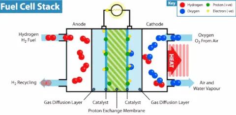
The efficiency of the fuel cell described above in the generation of electricity generally approximates to 70% whereas thermal power plants have an efficiency of 40%. This substantial difference in efficiency is because the generation of electric current in a thermal power plant involves the conversion of water into steam, and the usage of this steam to rotate a turbine. Fuel cells, however, offer a platform for the direct conversion of chemical energy into electrical energy.
Types of Fuel Cell
Fuel cells are classified primarily by the kind of electrolyte they employ. This classification determines the kind of electro-chemical reactions that take place in the cell, the kind of catalysts required, the temperature range in which the cell operates, the fuel required, and other factors. These characteristics, in turn, affect the applications for which these cells are most suitable. There are several types of fuel cells currently under development, each with its own advantages, limitations, and potential applications. Learn more about the following types of fuel cells.
* Polymer electrolyte membrane (PEM) fuel cells
Polymer electrolyte membrane (PEM) fuel cells—also called proton exchange membrane fuel cells—deliver high power density and offer the advantages of low weight and volume compared with other fuel cells. PEM fuel cells use a solid polymer as an electrolyte and porous carbon electrodes containing a platinum or platinum alloy catalyst. They need only hydrogen, oxygen from the air, and water to operate. They are typically fueled with pure hydrogen supplied from storage tanks or reformers.
PEM fuel cells operate at relatively low temperatures, around 80°C (176°F). The low-temperature operation allows them to start quickly (less warm-up time) and results in less wear on system components, resulting in better durability. However, it requires that a noble-metal catalyst (typically platinum) be used to separate the hydrogen's electrons and protons, adding to the system cost. The platinum catalyst is also extremely sensitive to carbon monoxide poisoning, making it necessary to employ an additional reactor to reduce carbon monoxide in the fuel gas if the hydrogen is derived from a hydrocarbon fuel. This reactor also adds cost.
Application:
- PEM fuel cells are used primarily for transportation applications and some stationary applications.
- PEM fuel cells are particularly suitable for use in vehicle applications, such as cars, buses, and heavy-duty trucks.
* Solid oxide fuel cells (SOFCs)
Solid oxide fuel cells (SOFCs) use a hard, non-porous ceramic compound as the electrolyte. SOFCs are around 60% efficient at converting fuel to electricity. In applications designed to capture and utilize the system's waste heat (co-generation), overall fuel use efficiencies could top 85%.
SOFCs operate at very high temperatures—as high as 1,000°C (1,830°F). The high-temperature operation removes the need for a precious-metal catalyst, thereby reducing cost. It also allows SOFCs to reform fuels internally, which enables the use of a variety of fuels and reduces the cost associated with adding a reformer to the system.
SOFCs are also the most sulfur-resistant fuel cell type; they can tolerate several orders of magnitude more sulfur than other cell types can. In addition, they are not poisoned by carbon monoxide, which can even be used as fuel. This property allows SOFCs to use natural gas, biogas, and gases made from coal. High-temperature operation has disadvantages. It results in a slow startup and requires significant thermal shielding to retain heat and protect personnel, which may be acceptable for utility applications but not for transportation. The high operating temperatures also place stringent durability requirements on materials. The development of low-cost materials with high durability at cell operating temperatures is the key technical challenge facing this technology.
Scientists are currently exploring the potential for developing lower-temperature SOFCs operating at or below 700°C that have fewer durability problems and cost less. Lower-temperature SOFCs have not yet matched the performance of the higher temperature systems, however, and stack materials that will function in this lower temperature range are still under development.
* Alkaline fuel cells
Alkaline fuel cells (AFCs) were one of the first fuel cell technologies developed, and they were the first type widely used in the U.S. space program to produce electrical energy and water on-board spacecraft. These fuel cells use a solution of potassium hydroxide in water as the electrolyte and can use a variety of non-precious metals as a catalyst at the anode and cathode. In recent years, novel AFCs that use a polymer membrane as the electrolyte have been developed. These fuel cells are closely related to conventional PEM fuel cells, except that they use an alkaline membrane instead of an acid membrane. The high performance of AFCs is due to the rate at which electro-chemical reactions take place in the cell. They have also demonstrated efficiencies above 60% in space applications.
A key challenge for this fuel cell type is that it is susceptible to poisoning by carbon dioxide (CO2). In fact, even the small amount of CO2 in the air can dramatically affect cell performance and durability due to carbonate formation. Alkaline cells with liquid electrolytes can be run in a recirculating mode, which allows for electrolyte regeneration to help reduce the effects of carbonate formation in the electrolyte, but the recirculating mode introduces issues with shunt currents. The liquid electrolyte systems also suffer from additional concerns including wettability, increased corrosion, and difficulties handling differential pressures. Alkaline membrane fuel cells (AMFCs) address these concerns and have lower susceptibility to CO2 poisoning than liquid-electrolyte AFCs do. However, CO2 still affects performance, and the performance and durability of the AMFCs still lag that of PEMFCs. AMFCs are being considered for applications in the W to kW scale. Challenges for AMFCs include tolerance to carbon dioxide, membrane conductivity and durability, higher temperature operation, water management, power density, and anode electrocatalysis.
Application:
On the worldwide automobile market, technical developments are increasingly determined by the dramatic restriction on emissions as well as the regimentation of fuel consumption by legislation. Therefore there is an increasing chance of a completely new technology breakthrough if it offers new opportunities, meeting the requirements of resource preservation and emission restrictions. Fuel cell technology offers the possibility to excel in today's motive power techniques in terms of environmental compatibility, consumer profit, costs of maintenance, and efficiency. The key question is economy. This will be decided by the costs of fuel cell systems if they are to be used as power generators for future electric vehicles. The alkaline hydrogen-air fuel cell system with circulating KOH electrolyte and low-cost catalysed carbon electrodes could be a promising alternative.
* Direct methanol fuel cells
Most fuel cells are powered by hydrogen, which can be fed to the fuel cell system directly or can be generated within the fuel cell system by reforming hydrogen-rich fuels such as methanol, ethanol, and hydrocarbon fuels. Direct methanol fuel cells (DMFCs), however, are powered by pure methanol, which is usually mixed with water and fed directly to the fuel cell anode.
Direct methanol fuel cells do not have many of the fuel storage problems typical of some fuel cell systems because methanol has a higher energy density than hydrogen—though less than gasoline or diesel fuel. Methanol is also easier to transport and supply to the public using our current infrastructure because it is a liquid, like gasoline.
Applications:
- DMFCs are often used to provide power for portable fuel cell applications such as cell phones or laptop computers.
Comparison
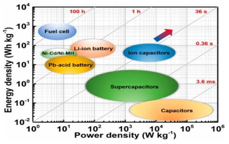
2) Using a plot with energy density and power density on the X and Y axis, arrange various battery types like lithium-ion, lead acid, Nickel Cadmium, Ultracapacitor, and fuel cell.
- As per the shown figure, it is understood that the capacitors are having High power density.
- Then comes the Supercapacitors.
- Fuel cells are high in energy density. The battery is leftover In between supercapacitors and fuel cel
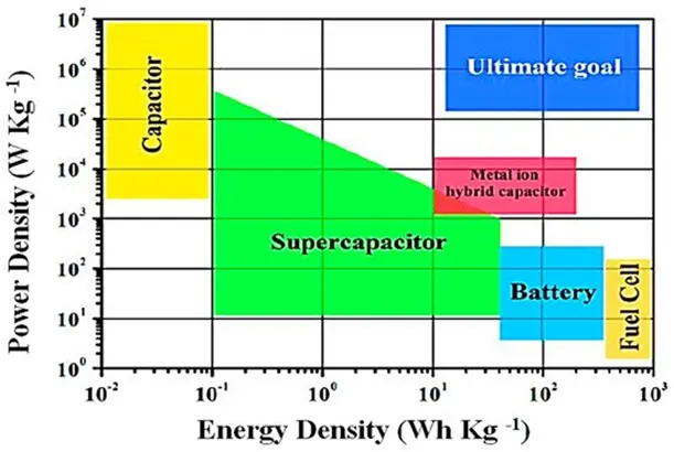
- In this figure, the power density of electrostatic capacitors is high with a low energy density
- Fuel cells have the highest energy density with a low power density
- The best option is electrochemical capacitors with better values of power and energy densities.
- The Ragone plot is very useful for estimating energy storage performance but ignores the critical features, such as cycle life, cost estimation, and safety for comparison between supercapacitors and batteries.
- For a better comparison and understanding of energy storage technology, it is important to consider safety, cost estimation, and cycle life. In supercapacitors, carbon nano-tubes, carbon nanofibers, and graphene are used.
- The main disadvantage of carbon nanotubes is the lack of solubility in aqueous media. The carbon nanofibers are toxic and graphene is bad for humans and the environment. Better electrode materials are required for the improvement of supercapacitors.
- The main difference in batteries and supercapacitors is the storage formula, energy storage amount, power restrictions, and life
- The cyclic life of a supercapacitor is 1 million to 30,000 h, i.e., extraordinarily higher than the batteries, which are 500 h, and the recharging time for the supercapacitor is remarkably low, i.e., 1–10 s vs. battery 10–60 min.
- One of the most attractive features of a supercapacitor is thermal stability, which is tuned by a wise choice of materials, including electrolytes.
- The operating temperature of the battery is between −20 and 60 °C, and that of the supercapacitor is between −40 and 100 °C.
- In supercapacitors, the potential energy deposits in the electric field, whereas batteries store potential energy in the form of chemical energy.
- The batteries provide a higher energy density for the storage of power, while the supercapacitors have a faster charging and discharging capability, which makes them more attractive than the batteries.
- Supercapacitors are designed to provide (a) high power, (b) long stability, and (c) efficient storage, because the electrodes are highly absorbable materials. However, their disadvantages, such as low energy density as well as specific capacitance, make them unfit for applications where energy is required long term .
- The use of a scalable nano-porous graphene synthesis mechanism involves heating hydrogen; the graphene supercapacitors have a quality of energy density, better than lithium batteries .
- The supercapacitor is made up of spongy and porous material, with an extraordinarily high specific area. The smaller pores of the plates increase the ESR, which finally decreases the specific power.
-
The supercapacitor fully charges within 1–10 s. The charging characteristics of a supercapacitor are similar to that of an electrochemical battery. The charging current is limited by the charger's current handling capability. The initial charging is very fast, but the topping charging takes extra time.
-
In constant current charging, a supercapacitor holds a voltage that rises linearly with time. During this constant current charging phase, the chargers typically monitor the output current, influencing the voltage across an external sensor (resistor) .
-
The lifetime of supercapacitors is more than batteries.
-
Even though the initial cost of the supercapacitors is very high, almost $2400–$6000 per kilowatt-hour for energy storage, and lithium-ion batteries are used for electric vehicles, with an initial cost $500 to $1000 per kWh; although the initial cost of supercapacitors high, in long term the supercapacitors are cheaper/comparable.
#CONCLUSION
Studied about four different types of fuel cells and state their applications, and Ragone plot