Week 2 Challenge
Challenge 2
Submitted by Kanala Rahul Reddy
1. What are workspaces and worksets? List Civil-specific variables (min. 5). Where are the workspaces saved on the computer (default location)?
WorkSpace:
A Workspace is a collection of projects, standards, and other related resources. In general, a WorkSpace is a place where the DOTs store their “Department Standards”, resources, libraries, and custom applications such as levels, cells, line styles, feature definitions, macros, pen tables/design scripts, color table/book, unit definitions (miles/feet English vs. kilometers/meters Metric), Design Standards, seed files, etc.
Workset:
In general, a WorkSet is the “Project” or plan set using the resources and standards of a WorkSpace.
A WorkSpace is the “parent” of a WorkSet Workspaces and Worksets are used in OpenBuildings Energy Simulator to save project data. These set up a folder structure that allows for effective management of preferences, such as standards, custom constructions, and schedules.
Civil-specific variables:
- CIVIL_CIVILTMDGNLIBLIST
- CIVIL_DISALLOW_LOCKCHANGES
- CIVIL_CIVILSETTINGS_READONLY
- CIVIL_SHOW_SHARED_FEATUREDEF_PROPS
- CIVIL_EXAGGERATION_VALUES
- CIVIL_DEFAULTSETTINGS
- CIVIL_DEFAULT_LINEAR_STROKING
Save Location:
Workspace Folder: C:\ProgramData\Bentley\OpenRoads Designer CE\Configuration\WorkSpaces\Indian
Workset Folder: C:\ProgramData\Bentley\OpenRoads Designer CE\Configuration\WorkSpaces\Indian\WorkSets
2. What are feature definitions? What is a broader classification of feature definition types?
A Feature Definition controls how each feature is displayed and how it interacts with various tasks. The first time you use a Feature Definition it is copied into your active DGN and can then be modified.
- Properties are used to define how a feature is to be displayed, annotated, computed, etc.
- These are normally customized by each organization.
- These are normally created in advance and propagated across an organization in order to standardize designs.
Types of Feature Definitions
3 types of feature definitions are supported depending on its type, a feature definition will have various properties that are available for definition.
Point Feature
- R/W Marker
- Control Point
- Iron Pin
Linear Feature
- Curb & Gutter
- Wall
- Ditch
Surface Feature
- Existing Ground
- Aggregate Base
- Asphalt Pavement
3. Create a dgn file with a 2D imperial seed file and a 3D imperial seed file. Save it in the project data folder, creating a new folder named DGN from SEED.
Aim: To create a dgn file with a 2D imperial seed file and a 3D imperial seed file.
Introduction:
Seed file is a term for a template. When a user selects File/New, the application makes a copy of the selected seed file, puts it in the desired folder, and the dgn is given a new name. The Default model has the Default-3D model (attached with live nesting) which has the MX model attached to it. So you can see all the information in the dgn when the Default Model is open. Individual Windows can view different models of the 3D information even when in the Default 2D model.
Procedure:
Step1: Opening Open Roads Designer
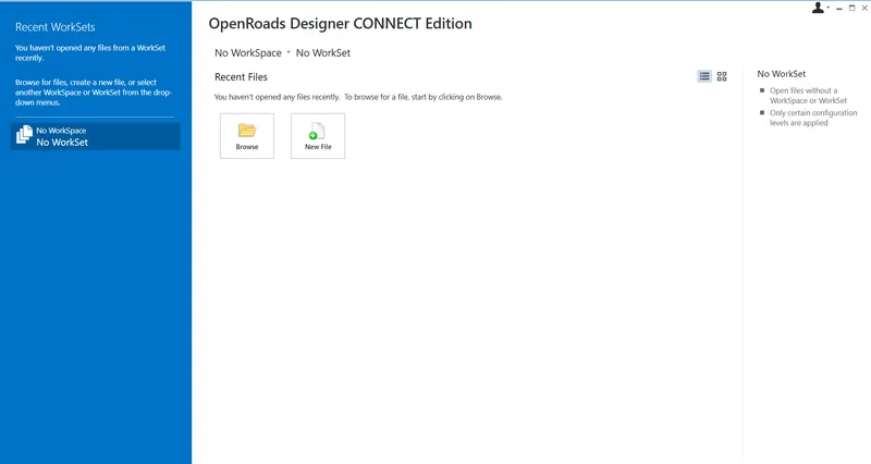
Step 2: Creating a New 2D dgn file from the 2D seed file
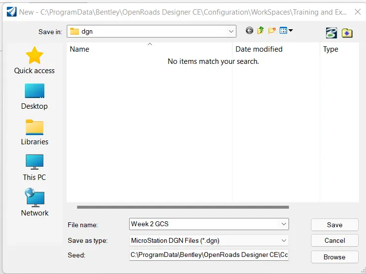
Click on New File to open a window
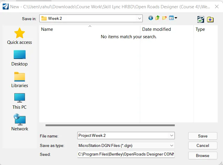
Click on the 'Browse Option' adjacent to the Seed file to set the seed file
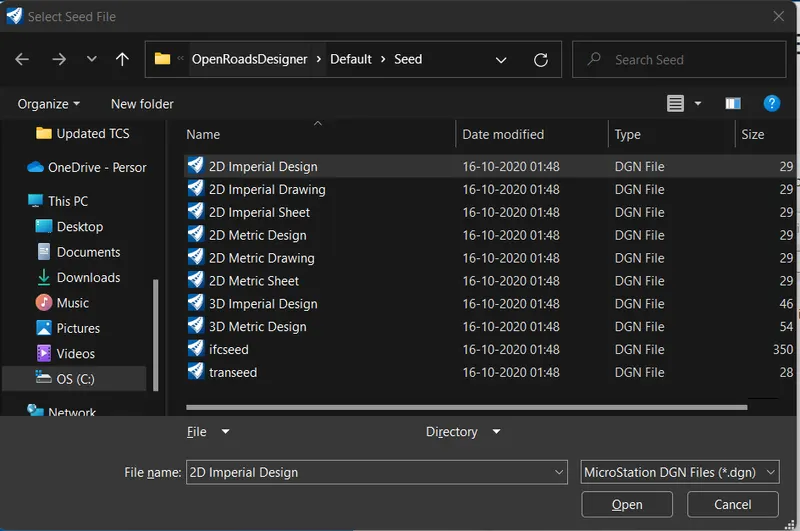
Select the 2D Imperial Design Seed File and Click open
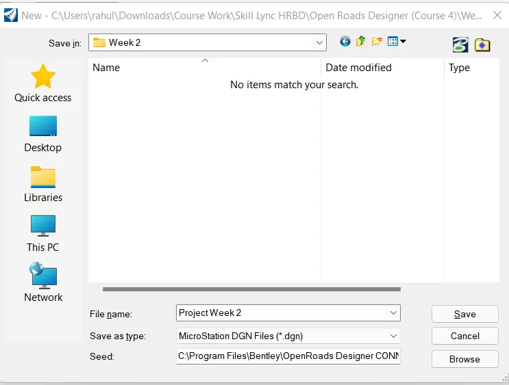
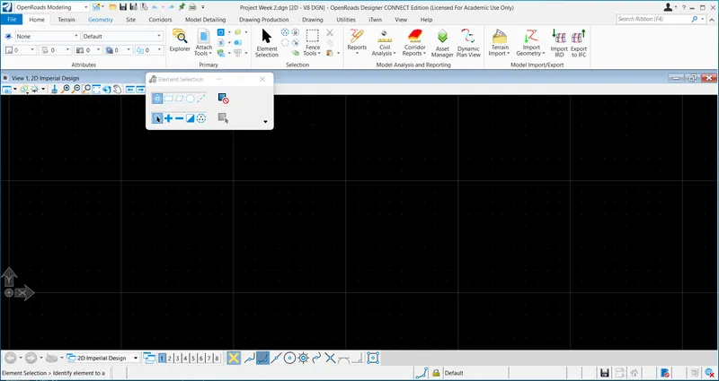
Click on save to open the DGN file with 2D Imperial Seed File
Step 3: Creating a New 3D dgn file from the 3D seed file
Click on New File to open a window
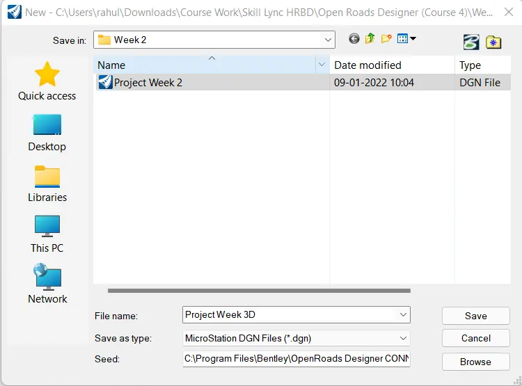
Click on the 'Browse Option' adjacent to the Seed file to set the seed file
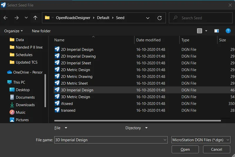
Select the 3D Imperial Design Seed File and Click open
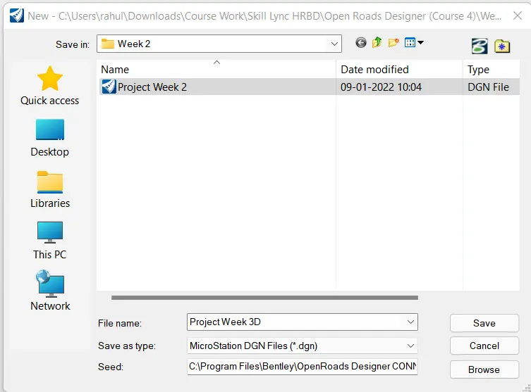
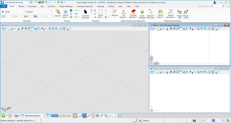
Click on save to open the DGN file with 3D Imperial Seed File
Result:
2D dgn File
3D dgn file
4. Set geographic coordinate system to TX-83, North Central zone, US survey foot. Turn on the background imagery. Save this file with save settings.
Aim: To Set geographic coordinate system
Introduction:
The geographic coordinate system (GCS) is a spherical or ellipsoidal coordinate system for measuring and communicating positions directly on the Earth as latitude and longitude.[1] It is the simplest, oldest, and most widely used of the thousands of spatial reference systems that are in use, and forms the basis for most others. Although latitude and longitude form a coordinate tuple like a cartesian coordinate system, the geographic coordinate system is not cartesian because the measurements are angles and are not on a planar surface.
Procedure:
Step1: Opening Open Roads Designer
Open a new file with a 2D seed file as shown below
Step 2: Setting Coordinates
- Go to the 'Utilities' tab
- Click on the 'Coordinate system'
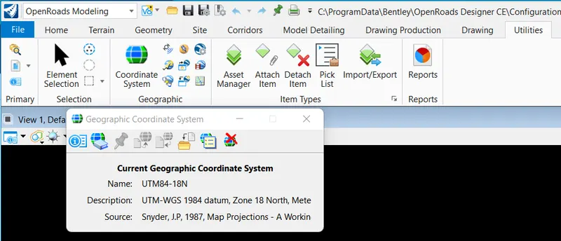
- Click on From Library and change the coordinate system
- From Popup go to the Search tab and search for TX-83, North Central zone
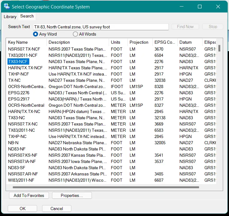
- Click ok to set the coordinate system
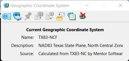
Step 3: Opening Background Imagery
Go to view attributes as shown below
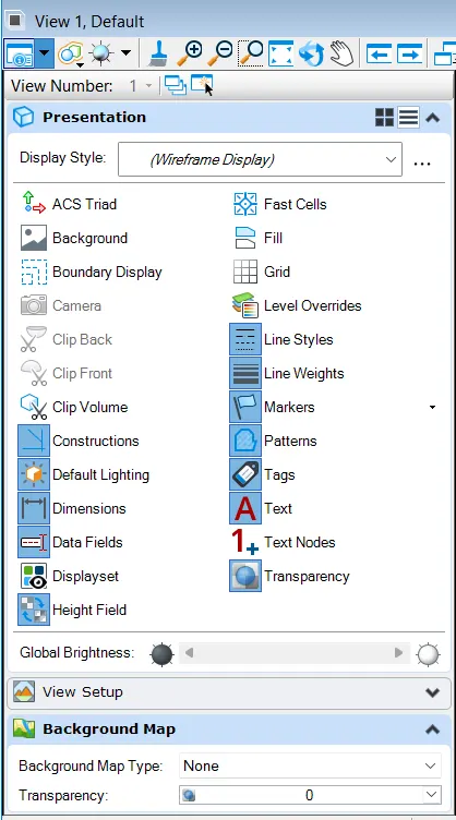
Set the background map as Hybrid
Result:
After setting the coordinate system and turning on the Background imagery the result is as follows
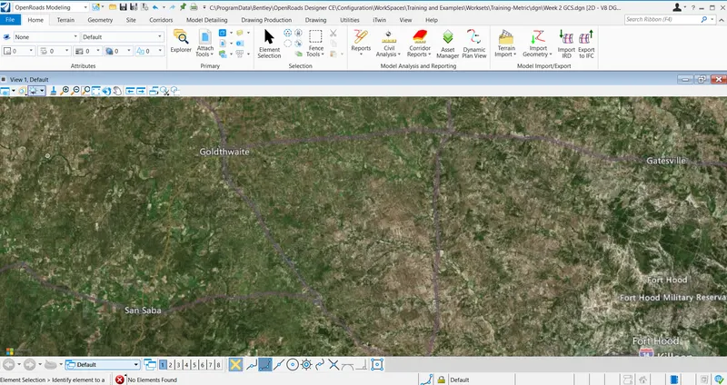
5. Attach the survey file from the SURVEY folder to the newly created 2D dgn in above #3
Aim: Attach the survey file from the SURVEY folder to the newly created 2D dgn
Introduction:
In Insight, a survey refers to the navigational positioning of a dataset (the IL/CL or Line/CMP to X/Y relationship). Data is stored in Volumes. See Survey Overview for more details. In most cases, surveys are created when loading data into Insight from SEG-Y (see Defining a Survey (3D SEG-Y)), navigation data, or over the data links. Survey geometry can be also specified in text files and imported into Insight. By default, Insight expects the extension ".survey". The format varies between 2D and 3D surveys.
Procedure:
Step 1: Opening Open Roads Designer
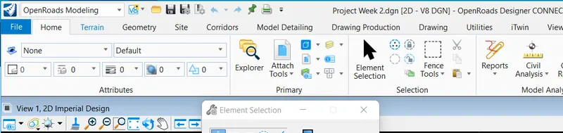
Open the file created with a 2D seed file as shown below
Step 2: Opening Survey File
- Go to the Primary tab and click on 'Attach Tools'
- Click on References to attach the survey file
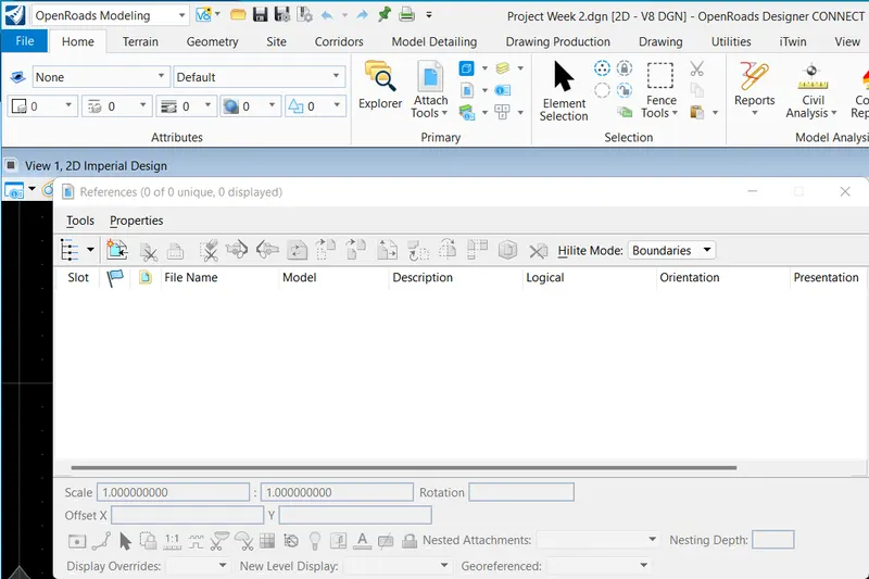
- Click on 'Attach Refference'
- Select the 'TOPO' file
- Set Attachment method as interactive
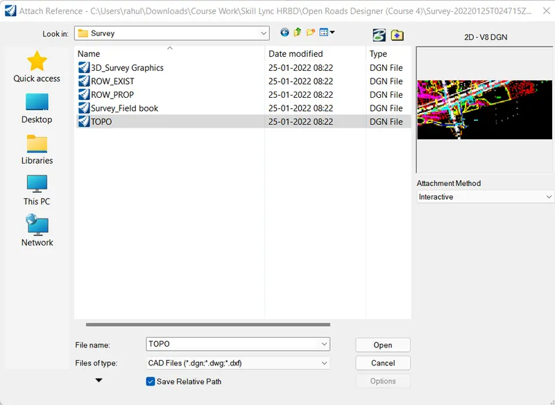
- Click open
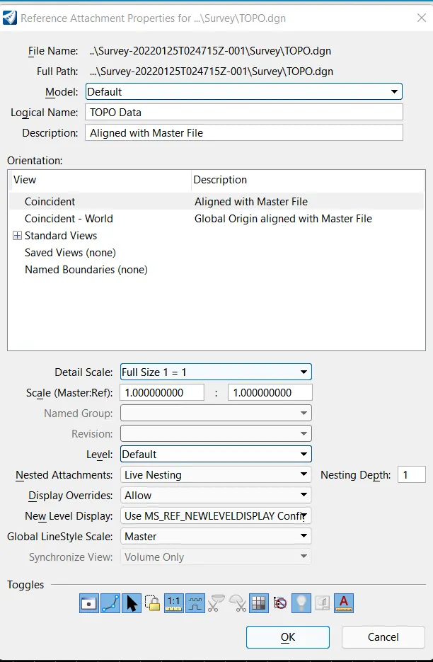
- Set the Logic name as Topo
- Set Nesting as Live Nesting and set Nesting depth as 1
Click on Fit view to fit the topo data in the screen
Result:
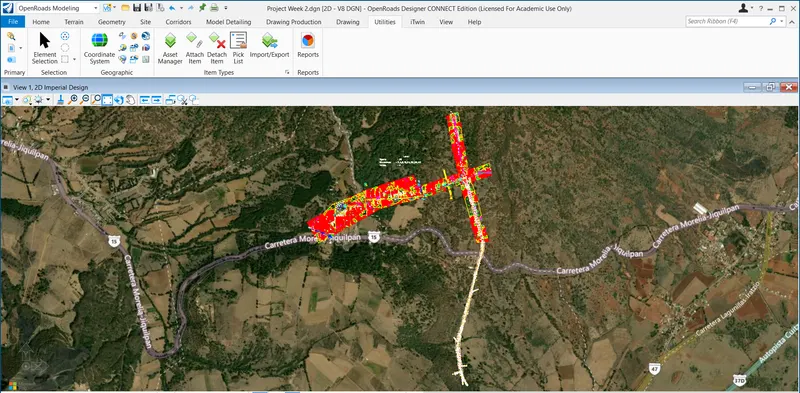
After attaching the topo data the result is as follows