Residence Plan, Seating Plan and Toilet and Utility room Plan
Week 4 Challenges
Submitted by Kanala Rahul Reddy
Challenge 1
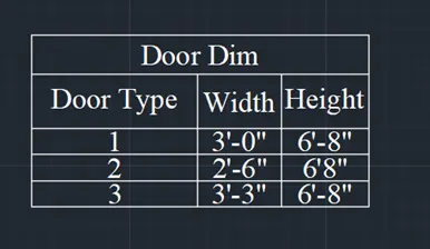
Residence Plan: Sketch the layout of a residence as shown in the Figure 1. Consider all dimensions as reference to sketch the unit plan. Also, the text in the layout are only for reference. Assume the missing dimensions. Also, refer the schedule for size of the doors.
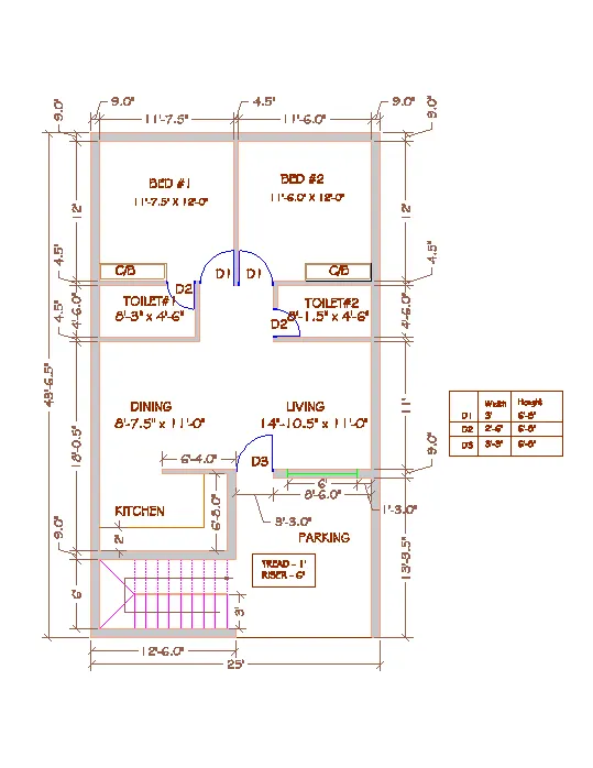
Aim: To draw the layout of a residence as shown in the above figure in Auto CAD
Introduction: The plan is for a residential building with two bedrooms, two toilets, living room, dining room, a kitchen and parking area.
Procedure:
Open AutoCAD
In Startup settings start from scratch select Imperial (Feet and inches)
Open grid and snap settings
- Change snap and grid spacing to 1’
- Change major line every grid line to 10’
- Turnoff adaptive grid
Type ‘un’ in command box and press enter
Change units’ type to architectural and precision to 1’1/16”
Step 1: Drawing External walls
Type ‘rec’ or rectangle in the command box or select rectangle from the draw toolbar
- Specify first corner point: Type (10’,10’) and press enter
- Specify other corner point or [ Area: Dimension: Rotation]: Click on dimensions
- Specify length for rectangle: Type 25’ and press enter
- Specify width for rectangle: Type 43’6.5” and press enter and set the direction as first quadrant
Type ‘o’ and press enter or click offset from the modify tool bar
- Specify offset distance: Type 9” and press enter
- Select object to offset: Select the rectangle drawn earlier and select the inside of the rectangle
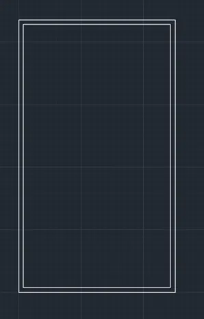
Type ‘expl’ or explode in the command box and press enter
- Select objects: Select the inner rectangle
Type ‘o’ and press enter or click offset from the modify tool bar
- Specify offset distance: Type 6’ and press enter
- Select object to offset: Select the bottom edge of inner rectangle
Type ‘o’ and press enter or click offset from the modify tool bar
- Specify offset distance: Type 12’6” and press enter
- Select object to offset: Select the left edge of inner rectangle
Type ‘o’ and press enter or click offset from the modify tool bar
- Specify offset distance: Type 9” and press enter
- Select object to offset: Select the bottom offset line drawn and click on top of the line
Type ‘o’ and press enter or click offset from the modify tool bar
- Specify offset distance: Type 9” and press enter
- Select object to offset: Select the left offset line drawn and click on left side of the line
Type ‘o’ and press enter or click offset from the modify tool bar
- Specify offset distance: Type 6’8” and press enter
- Select object to offset: Select the wall thickness offset line drawn horizontally earlier and click on top of the line
Type ‘o’ and press enter or click offset from the modify tool bar
- Specify offset distance: Type 4.5 and press enter
- Select object to offset: Select the last offset horizontal line and click on top
Type extend in command box and press enter
- Select objects: Select the right edge of inner rectangle and press enter
- Extend: Select the offset line wall of kitchen drawn
Type ‘o’ and press enter or click offset from the modify tool bar
- Specify offset distance: Type 9” and press enter
- Select object to offset: Select the extended line drawn and click on down side of the line
Type ‘tr’ or trim in command box or select trim from the modify tool bar
- Select objects: Press enter to select all the objects
- Trim: Trim the extra portions of offset line drawn, wall inner positions etc.
Delete or erase all the extra lines
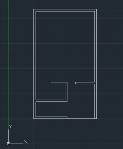
Step 2: Drawing Internal walls
Type ‘o’ and press enter or click offset from the modify tool bar
- Specify offset distance: Type 12’ and press enter
- Select object to offset: Select the top edge of inner rectangle and click on the bottom of the line
Type ‘o’ and press enter or click offset from the modify tool bar
- Specify offset distance: Type 4.5” and press enter
- Select object to offset: Select the last offset line drawn from top edge of inner rectangle and click on the bottom side of the line as wall thickness
Type ‘o’ and press enter or click offset from the modify tool bar
- Specify offset distance: Type 4’6” and press enter
- Select object to offset: Select the last offset line drawn with wall thickness and click on bottom of the line
Type ‘o’ and press enter or click offset from the modify tool bar
- Specify offset distance: Type 4.5” and press enter
- Select object to offset: Select the last offset line drawn as wall thickness and click on the bottom of the line
Type ‘o’ and press enter or click offset from the modify tool bar
- Specify offset distance: Type 11’7.5” and press enter
- Select object to offset: Select the left edge of inner rectangle and click on the right of the line
Type ‘o’ and press enter or click offset from the modify tool bar
- Specify offset distance: Type 8’3” and press enter
- Select object to offset: Select the left edge of inner rectangle and click on the right of the line
Type ‘o’ and press enter or click offset from the modify tool bar
- Specify offset distance: Type 8’1.5” and press enter
- Select object to offset: Select the right edge of inner rectangle and click on the left of the line
Type ‘o’ and press enter or click offset from the modify tool bar
- Specify offset distance: Type 4.5” and press enter
- Select object to offset: Select the last offset line and select on left of the line
- Select object to offset: Select the center offset line and select on right of the line
- Select object to offset: Select the left offset line drawn at 8’3” and select on right of the line
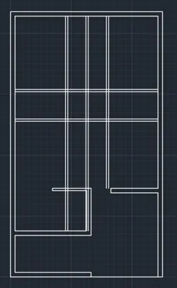
Type ‘tr’ or trim in command box or select trim from the modify tool bar
- Select objects: Press enter to select all the objects
- Trim: Trim the extra portions of offset lines drawn, door openings and wall inner positions etc. Trim as follows
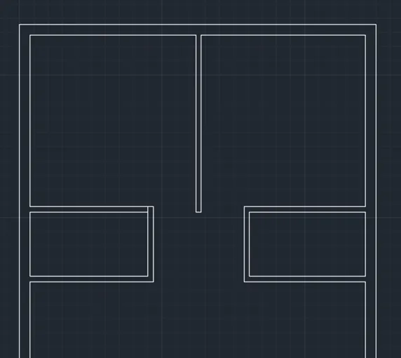
Door Openings
Type ‘L’ or line in command box or select line command from draw tool bar
- Specify first point: Turn on polar tracking and select the right inner wall thickness edge of toilet 1 and start polar tracking to the left, then type 2’6” and press enter
- Specify next point: Turn on OSNAP and perpendicular option and draw a line perpendicular the last point
Repeat the same step for toilet 2
Type ‘L’ or line in command box or select line command from draw tool bar
- Specify first point: Turn on polar tracking and select the right inner wall thickness edge of toilet 2 and start polar tracking to the top, then type 2’6” and press enter
- Specify next point: Turn on OSNAP and perpendicular option and draw a line perpendicular the last point
Type ‘tr’ or trim in command box or select trim from the modify tool bar
- Select objects: Press enter to select all the objects
- Trim: Trim the extra portions of offset lines drawn at door openings. Trim as follows
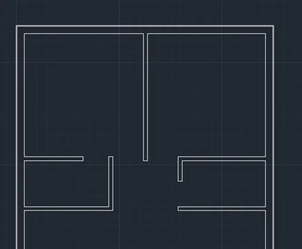
Step 3: Drawing Doors and placing doors
Door Type 1:
Type ‘L’ or line in command box or select line command from draw tool bar
- Specify first point: Turn on grid and select a point in the grid
- Specify next point: Turn on orthomode and keep the curser left of previous point and type 1.5” and press enter
- Specify next point: Keep the curser top of previous point and type 3’ and press enter
- Specify next point: Keep the curser right of previous point and type 0.75” and press enter
- Specify next point: Keep the curser down of previous point and type 3’ and press enter
Select Start center End in the arc tool dropdown from the draw tool bar
- Specify start point of arc: Select the top of the rectangle drawn before
- Specify center point of arc: Select the bottom point of the rectangle making radius as 3’
- Specify end point of arc: select the third point on left side of rectangle with radius 3’
Door Type 2:
Type ‘L’ or line in command box or select line command from draw tool bar
- Specify first point: Turn on grid and select a point in the grid
- Specify next point: Turn on orthomode and keep the curser left of previous point and type 1.5” and press enter
- Specify next point: Keep the curser top of previous point and type 2’6” and press enter
- Specify next point: Keep the curser right of previous point and type 0.75” and press enter
- Specify next point: Keep the curser down of previous point and type 2’6” and press enter
Select Start center End in the arc tool dropdown from the draw tool bar
- Specify start point of arc: Select the top of the rectangle drawn before
- Specify center point of arc: Select the bottom point of the rectangle making radius as 2’6”
- Specify end point of arc: select the third point on left side of rectangle with radius 2’6”
Door Type 3:
Type ‘L’ or line in command box or select line command from draw tool bar
- Specify first point: Turn on grid and select a point in the grid
- Specify next point: Turn on orthomode and keep the curser left of previous point and type 1.5” and press enter
- Specify next point: Keep the curser top of previous point and type 3’3” and press enter
- Specify next point: Keep the curser right of previous point and type 0.75” and press enter
- Specify next point: Keep the curser down of previous point and type 3’3” and press enter
Select Start center End in the arc tool dropdown from the draw tool bar
- Specify start point of arc: Select the top of the rectangle drawn before
- Specify center point of arc: Select the bottom point of the rectangle making radius as 3’3”
- Specify end point of arc: select the third point on left side of rectangle with radius 3’3”
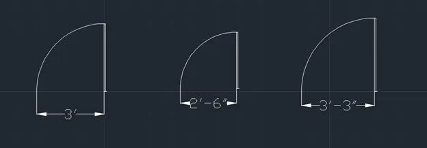
Placing Doors:
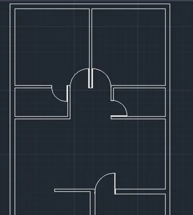
Select specific door and place them as per the plan by rotating them and mirroring them
Place Door type 1 at both the bedrooms as per plan
Place Door type2 at both bathrooms
Place Door type 3 at the main entrance
Step 4: Drawing Stairs and other furniture
Type ‘o’ and press enter or click offset from the modify tool bar
- Specify offset distance: Type 2’11” and press enter
- Select object to offset: Select the bottom edge of inner rectangle
Type ‘o’ and press enter or click offset from the modify tool bar
- Specify offset distance: Type 2” and press enter
- Select object to offset: Select the last offset line click on top of the line
Type ‘L’ or line in command box or select line command from draw tool bar
- Specify first point: Turn on OSNAP and select the right edge of bottom external wall
- Specify next point: Turn on OSNAP and select the point above the last selected point
Type ‘o’ and press enter or click offset from the modify tool bar
- Specify offset distance: Type 1’and press enter
- Select object to offset: Select the line drawn above and click on left side of the line
- Select object to offset: Select the last offset line drawn above and click on left side of the line
- Select object to offset: Select the last offset line drawn above and click on left side of the line
- Select object to offset: Select the last offset line drawn above and click on left side of the line
- Select object to offset: Select the last offset line drawn above and click on left side of the line
- Select object to offset: Select the last offset line drawn above and click on left side of the line
- Select object to offset: Select the last offset line drawn above and click on left side of the line
- Select object to offset: Select the last offset line drawn above and click on left side of the line
- Select object to offset: Select the last offset line drawn above and click on left side of the line
- Select object to offset: Select the last offset line drawn above and click on left side of the line
Delete the first line drawn
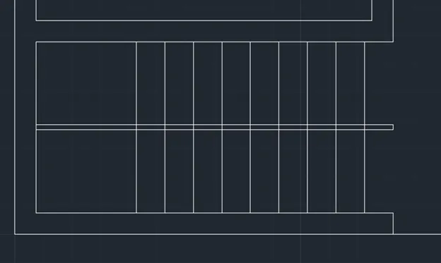
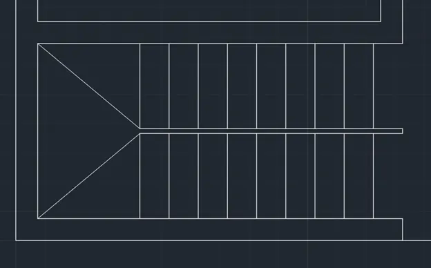
Type ‘tr’ or trim in command box or select trim from the modify tool bar
- Select objects: Press enter to select all the objects
- Trim: Trim the extra portions in the middle of offset lines drawn, and at left end. Trim as follows
Type ‘rec’ or rectangle in the command box or select rectangle from the draw toolbar
- Specify first corner point: Turn on OSNAP and select the bottom left corner of bedroom 1
- Specify other corner point: Keep the curser on top edge of wall at toilet door and start polar tracking to top and type 1’6” and press enter
Type ‘o’ and press enter or click offset from the modify tool bar
- Specify offset distance: Type 2” and press enter
- Select object to offset: Select the rectangle drawn above and click on inside of the rectangle
Type ‘co’ or copy in command box or select copy command from the modify tool bar
- Select Objects: Select the rectangles drawn previously
- Specify base point: Select the bottom right corner of the rectangles selected
- Specify second point: Select the bottom right corner of the bedroom 2

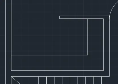
Type ‘o’ and press enter or click offset from the modify tool bar
- Specify offset distance: Type 2’and press enter
- Select object to offset: Select the top edge of wall just above the stairs at the kitchen
- Select object to offset: Select the right edge of kitchen wall
Trim off extra potions
Step 5: Creating Layers
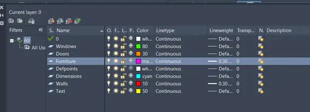
Open Layer properties and create new layers by clicking on new layer or right click on any layer and select new layer to create new layer
Layers are created as follows
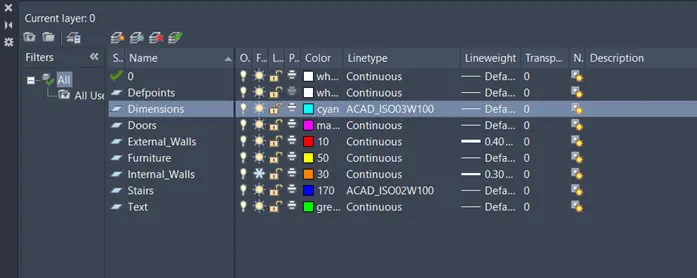
Assign layers to all components of the plan
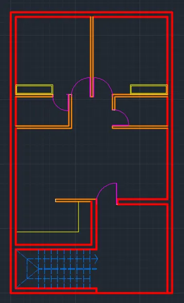
Result:
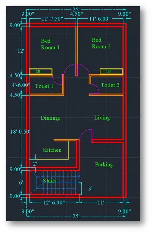
After assigning all the layers to all components of plan and adding dimensions and text with respective layers as shown above. The result is as follows
Notes:
- All dimensions are in Feet and Inches
- Except for external and internal wall all the other components are of normal thickness
- Door Dimensions
Challenge 2:
Sketch the seating plan for an outdoor canopy. Assume the dimensions for the seating. Also, consider the dimensions in mm.
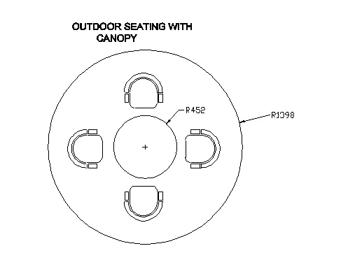
Aim: To draw the layout of outdoor seating with canopy
Introduction: The plan is for a outdoor seating table with four chairs
Procedure:
Open AutoCAD
In Startup settings start from scratch select Metric
Open grid and snap settings
- Change snap and grid spacing to 1
- Change major line every grid line to 10
- Turnoff adaptive grid
Type ‘un’ in command box and press enter
Change units’ type to Decimal and precision to 0.00 and insertion scale to millimeters
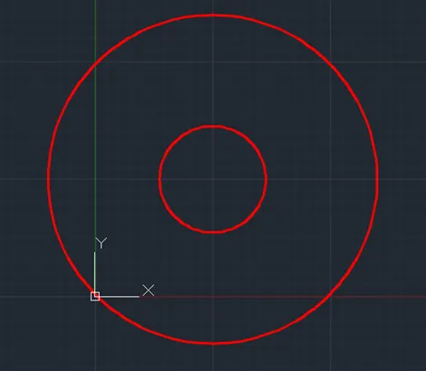
Step 1: Drawing circles
Type ‘C’ or Circle in the command box or select circle from the draw toolbar
- Specify center point for circle: Type 10,10 and press enter
- Specify radius of circle or Diameter: Type 4.52 and press enter
Type ‘C’ or Circle in the command box or select circle from the draw toolbar
- Specify center point for circle: Type 10,10 and press enter
- Specify radius of circle or Diameter: Type 13.98 and press enter
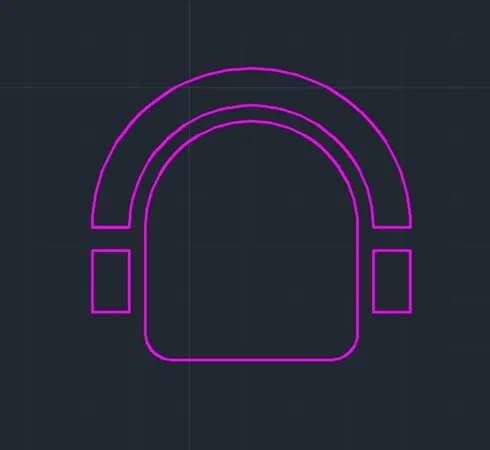
Step 2: Drawing chair
Type ‘C’ or Circle in the command box or select circle from the draw toolbar
- Specify center point for circle: Type 20,20 and press enter
- Specify radius of circle or Diameter: Type 2 and press enter
Type ‘C’ or Circle in the command box or select circle from the draw toolbar
- Specify center point for circle: Type 20,20 and press enter
- Specify radius of circle or Diameter: Type 2.3 and press enter
Type ‘C’ or Circle in the command box or select circle from the draw toolbar
- Specify center point for circle: Type 20,20 and press enter
- Specify radius of circle or Diameter: Type 2.8 and press enter
Type ‘L’ or line in command box or select line command from draw tool bar
- Specify first point: Turn on OSNAP and select the left end of circles drawn
- Specify next point: Turn on OSNAP and select the right end of circles drawn
Type ‘tr’ or trim in command box or select trim from the modify tool bar
- Select objects: Press enter to select all the objects
- Trim: Trim the bottom part of all the circles
Type ‘rec’ or rectangle in the command box or select rectangle from the draw toolbar
- Specify first corner point: Turn on OSNAP and select the left edge of semi-circle
- Specify other corner point: Turn on OSNAP and keep the curser on edge next to the last point and start polar tracking down and type 2 and press enter
Type ‘co’ or copy in command box or select copy command from the modify tool bar
- Select Objects: Select the rectangle drawn previously
- Specify base point: Select the bottom right corner of the rectangle selected
- Specify second point: Select the bottom right corner of the semi-circle
Type ‘rec’ or rectangle in the command box or select rectangle from the draw toolbar
- Specify first corner point: Turn on OSNAP and select the left edge of inner most semi-circle
- Specify other corner point: Turn on OSNAP and keep the curser on edge next to the last point and start polar tracking down and type 3 and press enter
Type ‘L’ or line in command box or select line command from draw tool bar
- Specify first point: Turn on OSNAP and select just below the left edge rectangle
- Specify next point: Turn on OSNAP and select perpendicular to right edge rectangle
Type ‘tr’ or trim in command box or select trim from the modify tool bar
- Select objects: Press enter to select all the objects
- Trim: Trim the extra portions as follows
Step 4: Array seating
Type ‘co’ or copy in command box or select copy command from the modify tool bar
- Select Objects: Select the entire chair
- Specify base point: Select the bottom center of the chair
- Specify second point: Place it just above the inner circle
Type ‘AR’ or array in command box or select array from the modify tool bar
- Select objects: Select the chair drawn earlier
- Select Array type [Rectangular Path Polar]: Select Polar
- Specify center point of array: Click on the common center of two circles drawn at the beginning
- Select the grip to edit array [items]: Click on items
- Enter number of items in the array: Type 4 and press enter
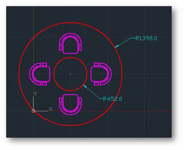
Result:
The result seating arrangement drawing is as follows
Notes
- All dimensions are in mm
Challenge 3
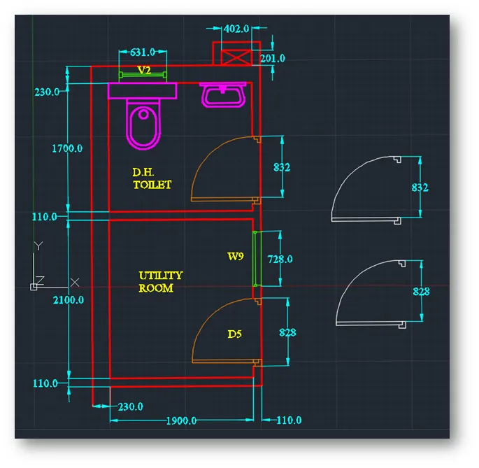
Sketch the part plan for the toilers and utilities room. Consider the outer wall thickness as 300mm and inner wall thickness as 150mm. Also, assume the missing dimension, Texts, dimensions, and hatches are only for references. Also, symbols for toilets and w/c are also for references.
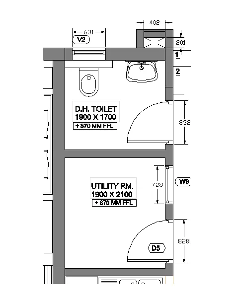
Aim: To draw the layout of Toilet and Utility room
Introduction: The plan is for a Toilet and Utility room with
Procedure:
Open AutoCAD
In Startup settings start from scratch select Metric
Open grid and snap settings
- Change snap and grid spacing to 1
- Change major line every grid line to 10
- Turnoff adaptive grid
Type ‘un’ in command box and press enter
Change units’ type to Decimal and precision to 0.00 and insertion scale to millimeters
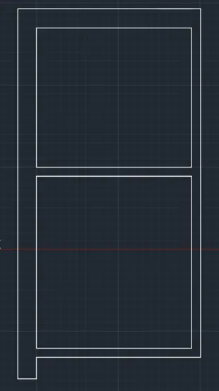
Step 1: Drawing External and Internal walls of Bathroom
Type ‘rec’ or rectangle in the command box or select rectangle from the draw toolbar
- Specify first corner point: Type (10,10) and press enter
- Specify other corner point or [ Area: Dimension: Rotation]: Click on dimensions
- Specify length for rectangle: Type 19 and press enter
- Specify width for rectangle: Type 17 and press enter and set the direction as first quadrant
Type ‘expl’ or explode in the command box and press enter
- Select objects: Select the rectangle
Type ‘o’ and press enter or click offset from the modify tool bar
- Specify offset distance: Type 2.3 and press enter
- Select object to offset: Select the top edge of rectangle
- Select object to offset: Select the left edge of rectangle
Type ‘o’ and press enter or click offset from the modify tool bar
- Specify offset distance: Type 1.1 and press enter
- Select object to offset: Select the right edge of rectangle
- Select object to offset: Select the bottom edge of rectangle
Type ‘rec’ or rectangle in the command box or select rectangle from the draw toolbar
- Specify first corner point: Select the left end of bottom offset line
- Specify other corner point or [ Area: Dimension: Rotation]: Click on dimensions
- Specify length for rectangle: Type 19 and press enter
- Specify width for rectangle: Type 21 and press enter and set the direction as fourth quadrant
Type ‘expl’ or explode in the command box and press enter
- Select objects: Select the second rectangle
Type ‘o’ and press enter or click offset from the modify tool bar
- Specify offset distance: Type 2.3 and press enter
- Select object to offset: Select the left edge of rectangle
Type ‘o’ and press enter or click offset from the modify tool bar
- Specify offset distance: Type 1.1 and press enter
- Select object to offset: Select the right edge of rectangle
- Select object to offset: Select the bottom edge of rectangle
Type ‘f’ or fillet in the command box and press enter or select fillet command from the modify tool bar
- Select first object: Select the any object need to be extended
- Select second object [Radius]: Click on radius
- Specify fillet radius: Type 0 and press enter
- Select second object: Select the object upto which the line needs to be extended
Type ‘rec’ or rectangle in the command box or select rectangle from the draw toolbar
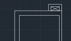
- Specify first corner point: Select the top right corner of inner rectangle polar track it to top and click
- Specify other corner point or [ Area: Dimension: Rotation]: Click on dimensions
- Specify length for rectangle: Type 4.02 and press enter
- Specify width for rectangle: Type 2.01 and press enter and set the direction as fourth quadrant
Type ‘o’ and press enter or click offset from the modify tool bar
- Specify offset distance: Type 1.1 and press enter
- Select object to offset: Select the rectangle drawn earlier
Trim off extra portions
Step 2: Creating Utilities
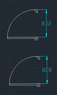
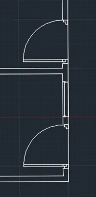
Doors are created using Line command and Start center end command of Arc and place them as follows
Creating Windows
Type ‘L’ or line in command box or select line command from draw tool bar
- Specify first point: Select a point on top wall about 50mm offset from wall edge
- Specify next point: Turn on orthomode and select a point perpendicular to the point created
Type ‘L’ or line in command box or select line command from draw tool bar
- Specify first point: Keep the curser on one end of line created earlier and polar track right and type 6.31 and press enter
- Specify next point: Turn on orthomode and select a point perpendicular to the point created
Type ‘rec’ or rectangle in the command box or select rectangle from the draw toolbar
- Specify first corner point: Select a nearest point to center of line created
- Specify another corner point: Select a point below the center of center of line created
Copy the rectangle to the other side
Type ‘L’ or line in command box or select line command from draw tool bar
- Specify first point: Select the center of first rectangle
- Specify next point: Select the center of second copied rectangle
Type ‘o’ and press enter or click offset from the modify tool bar
- Specify offset distance: Type 0.2 and press enter
- Select object to offset: Select the line drawn earlier and click on top of the line
- Select object to offset: Select the same line and click on bottom of the line
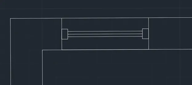
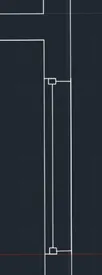
Similarly create the other window as follows
Toilet Utilities
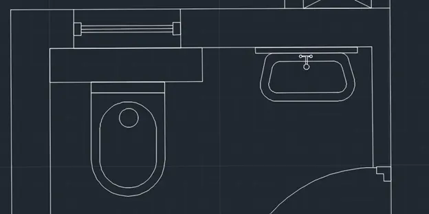
- Wash basin and Toilet are created and placed as follows
- They both are placed at an offset of 400mm
Step 3: Creating And assigning layers
Result:
The result seating arrangement drawing is as follows
Notes
- All dimensions are in mm