Week 2 Challenge
Question 1:
Compare four different types of fuel cells and state their applications.
Types of Fuel Cells
Proton Exchange Membrane Fuel Cell
The proton exchange membrane fuel cell is unusual in that its electrolyte consists of a layer of solid polymer which allows protons to be transmitted from one face to the other. It basically requires hydrogen and oxygen as its inputs, though the oxidant may also be ambient air, and these gases must be humidified. It operates at a low temperature because of the limitations imposed by the thermal properties of the membrane itself. The operating temperatures are around 90 °C. The PEMFC can be contaminated by carbon monoxide, reducing the performance by several percent for contaminant in the fuel in ranges of tens of percent. It requires cooling and management of the exhaust water in order to function properly.
There are a number of companies involved in manufacturing PEMFC. Ballard are probably the leaders, though companies such as DeNora in Italy and Siemens are progressing fast. The main focus of current designs is transport applications, as there are advantages to having a solid electrolyte for safety, and the heat produced by the fuel cell is not adequate for any form of cogeneration. Daimler-Benz has taken a high profile in developing cars powered by Ballard fuel cells, while Toyota has recently presented a vehicle that is using a fuel cell of their own design. Other car manufacturers, including General Motors and Ford, are actively engaged in similar developments. It now appears, however, that there is a strong possibility of using the PEMFC in very small scale localised power generation, where the heat could be used for hot water or space heating. There is also the possibility of a heater/chiller unit for cooling in areas where air conditioning is popular. If it does prove possible to use this particular type of fuel cell for both transport and power generation, then the advantages generated by economies of scale and synergy between the two markets could make the introduction of the technology easier than in other cases.
| Anode reaction: | H2 → 2H+ + 2e- |
| Cathode reaction: | ½O2 +2H+ + 2e- → H2O |
| Overall reaction: | H2 + ½O2 → H2O |
Solid Oxide Fuel Cells
Solid oxide fuel cells are constructed entirely from solid-state materials, using an ion-conducting oxide ceramic as the electrolyte, and are operated in the temperature range of 900-1000 °C. SOFC provide several advantages compared to other fuel cell types: they generate few problems with electrolyte management (to compare with liquid electrolytes, which are often corrosive and difficult to handle), they have the highest efficiencies of all fuel cells (50-60 %) and for combined heat and power applications internal reforming of hydrocarbon fuels is possible.
Current technology employs several ceramic materials for the active fuel cell components. The anode is typically constructed from an electronically conducting nickel/yttria-stabilised zirconia cermet (Ni/YSZ). The cathode is based on a mixed conducting perovskite, lanthanum manganate (LaMnO3). Yttria-stabilised zirconia (YSZ) is used as the oxygen ion conducting electrolyte. To generate a suitable voltage, fuel cells in the same stack are interconnect with a doped lanthanum chromate (eg La0.8Ca0.2CrO3) joining the anodes and cathodes of adjacent units. Although several stack designs are being considered around the world, the most common configuration is the planar (or "flat-plate") SOFC.
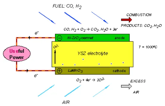
The high temperature range of SOFC operation is required for the YSZ electrolyte to provide sufficient oxygen ion conductivity. However, the cost to manufacture these devices is proving to be still very high, primarily because expensive high temperature alloys must be used for the balance-of-plant structures. These costs would be substantially reduced if the operating temperature could be lowered to between 600-800 °C, allowing the use of cheaper structural components, such as stainless steel. A lower operating temperature would also ensure a greater overall system efficiency and a reduction in the thermal stresses in the active ceramic structures, leading to a longer expected lifetime. To lower the operating temperature of SOFC, either the conductivity of YSZ must be improved, or alternative electrolytic materials must be developed to replace it. A concerted effort is being made by researchers around the globe to develop such materials. Ceramics that are currently being investigated include Gd-doped CeO2, Ba2In2O5 and (Sr,Mg)-doped LaGaO3 . However, these new materials all face serious drawbacks compared with YSZ, and it is most likely that the first commercial SOFC units will use zirconia-based ceramics as the electrolyte.
| Anode reactions: |
H2 + O2- → H2O +2e- CO + O2- → CO2 + 2e- |
| Cathode reaction: | O2 + 4e- → 22- |
| Overall reaction: | H2 + O2 + CO → H2O + CO2 |
Alkaline Fuel Cell
Low temperature aqueous alkaline electrolyte cells have the advantage of being able to start up easily from cold, and operate usually at 60-80 °C, where the water vapour pressure of the electrolyte is appopriately high for a controlled removal rate. At these temperatures, highly active catalysts are required, usually of the platinum family. Silver and high-surface nickel have been used, however, as catalysts in these system; nickel is conventionally used as a conducting structural material.
Cheaper catalysts normally require higher operating temperatures; the Bacon cell is an example of a nickel catalyst used at 200-250 °C. At these temperatures, either a high pressure must be applied to the system or highly concentrated solutions must be used to prevent water loss. High-pressure systems are not suitable for air operation, due to the high pumping energy required, whereas high concentration may cause corrosion, wich restricts the choice of construction materials.
The intolerance of this type of cell to carbon dioxide is a major problem; it restricts the choice of fuel to pure hydrogen of hydrazine, and requires that the air filter removes 0.04% of the CO2 present in the air. The internal reforming cell is an attempt to get rid of this problem : the fuel electrode is made of palladium plus silver, and the fuel is either alcohol or a hydrocarbon which is reformed with steam on a nickel catalyst on one side of the electrode. The hydrogen formed passes through the electrode and reacts with the electrolyte, but the palladium prevents the CO2 to passes through and get into the electrolyte.
| Anode reaction: | H2 + 2OH- → 2H2O + 2e- |
| Cathode reaction: | ½O2 + H2O + 2e- → 2OH- |
| Overall reaction: | H2 + ½O2 → H2O |
Sulfuric and Phosphoric Acid Fuel Cells
Acid electrolyte cells are more tolerant to CO2 and allow the use of normal air and non-pure hydrogen. But the corrosion problem restricts the choice of construction materials especially for the electrodes and the catalysts. The electrodes can be made out of gold, tatalum, titanium and carbon and only the platinum group metals can be used as catalysts. The acid used as the electrolyte must be non-volatile, such as sulfuric and phosphoric acids, so that only water is lost by evaporation.
The electrolyte in the PAFC is a paper matrix saturated with phosphoric acid, transporting the hydrogen ions. The operating temperature is around 200 °C. The operating temperature require platinum as catalyst which is supported being dispersed on graphite material. But platinum at this temperature is sensitive to CO-poisoning.
Cells wich use hydrocarbons directly as fuel around 150 °C have low efficiency and current density, thus have been restricted to research investigations. Alcohol fuels and impure hydrogen (containning CO and CO2 produced by reforming hydrocarbons) have been used by various compagnies.
In general, the performances of acid cells are much lower than that of alkaline cells, due to the poorer performances of the air electrode, probably because of the increased stability of formed perroxides in an acid environment. However there are many compromises that can be made between alkaline and acid fuel cells, considering the constructions and operating temperature and regarding the probable use of the desired cell.
| Anode reaction: | H2 → 2H+ + 2e- |
| Cathode reaction: | ½O2 +2H+ + 2e- → H2O |
| Overall reaction: | H2 + ½O2 → H2O |
Solid Polymer Fuel Cell
An example : the direct methanol fuel cells (DMFC)
This type of fuel cell is based on solid polymer technology but uses methanol directly as a fuel. If it can be made to work, that would be a big step forward in the automotive area where the storage or generation of hydrogen is one of the big obstacles for the introduction of fuel cells. Prototypes exist, but the development is at an early stage. There are principal problems, including the lower electrochemical activity of the methanol as compared to hydrogen, giving rise to lower cell voltages and, hence, efficiencies. Also, methanol is miscible in water, so some of it is liable to cross the water-saturated membrane and cause corrosion and exhaust gas problems on the cathode side. Nevertheless, the direct methanol fuel cell is an interesting proposition and a number of places are working on it, including Siemens in Germany, the University of Newcastle and Argonne National Laboratory. There are also efforts to develop a low-temperature SPFC (500 °C) that would also allow the direct use of methanol, as well as using stainless steel components. The idea is still young but intriguing. The Imperial College in London is active in this area.
| Anode reaction: | MeOH + H2O → CO2 + 6H+ + 6e- |
| Cathode reaction: | 3(½O2) + 6H+ + 6e- → 3H2O |
| Overall reaction: | MeOH + H2O+ 3(½O2) → CO2 + 3H2O |
Molten Carbonate Fuel Cell
In the molten carbonate fuel cell, the electrolyte consists of a molten mixture of potassium carbonate and lithium carbonate to transport carbonate-ions from the cathode to the anode. The CO32- transport needs supply of CO2 at the cathode side of the cell which is generally be obtained by recycling the anode off side gas. The operating temperature is about 850 °C which allows nickel to be used as catalyst material. The process occuring in a hydrogen-oxygen fuel cell operating at higher temperatures without an aqueous electrolyte might well be considered as oxide ions produces at the air electrode:
O2 + 4e- → 2O2-
which then move to the fuel electrode to oxidise the hydrogen:
H2 + O2- → H2O + 2e-
and it might therfore be considered that a molten ionic oxide would provide the best electrolyte to encourage this process. However, simple ionic oxides have melting points greater than 1000 °C and therefore attention has been focussed on salts melting at lower temperature. These salts are generally those with oxygen-containing anions, eg nitrates, sulfates, carbonates. At high temperature it is likely that the direct reaction of hydrocarbons at the fuel electrode is quite favorable and hence conversion of petroleum products to hydrogen or methanol is uneccessary. But consideration must be given to the effect of hydrocarbon oxidation at the fuel electrode on the choice of electrolyte. Carbon dioxide will be a major product that can be troublesome with some salts, for example:
CO2 + SO42- → CO32- + SO3
Hence it is most satisfactrory to consider as electrolyte a molten carbonate or mixture of carbonates. A mixture of salts may have a considerable advantage since it will have a lower melting point than either of its components. A convinient way of maintaining the carbonate composition of the electrolyte invariant is to remove carbon dioxide as a gaseous product from the fuel electrode and transfer it to the oxidant electrode in the air or oxygen stream. Thus for a fuel such as carbon monoxide the overall electrode processes will be:
O2 + 2CO2 + 4e- → CO32- and CO + CO32- → 2CO2 + 2e-
Thus carbonate ion transfert within the electrolyte may be balanced by carbon dioxid transfert outside it. A similar mechanism could operate even for cells using hydrogen as a fuel.
| Anode reaction: | H2 + CO32- → CO2 + H2O + 2e- |
| Cathode reaction: | ½O2 + CO2 + 2e- → CO32- |
| Overall reaction: | H2 + ½O2 → H2O |
| FUEL CELL TYPE | COMMON ELECTROLYTE | OPERATING TEMPERATURE | TYPICAL STACK SIZE | ELECTRICAL EFFICIENCY (LHV) | APPLICATIONS | ADVANTAGES | CHALLENGES |
|---|---|---|---|---|---|---|---|
| Polymer electrolyte membrane (PEM) | Perfluorosulfonic acid | <120°C | <1 kW–100 kW | 60% direct H2; 40% reformed fuel |
Backup power Portable power Distributed generation Transportation Specialty vehicles |
Solid electrolyte reduces corrosion and electrolyte management problems Low temperature Quick start-up and load following |
Expensive catalysts Sensitive to fuel impurities |
| Alkaline (AFC) | Aqueous potassium hydroxide soaked in a porous matrix, or alkaline polymer membrane | <100°C | 1–100 kW | 60% |
Military Space Backup power Transportation |
Wider range of stable materials allows lower cost components Low temperature Quick start-up |
Sensitive to CO2 in fuel and air Electrolyte management (aqueous) Electrolyte conductivity (polymer) |
| Phosphoric acid (PAFC) | Phosphoric acid soaked in a porous matrix or imbibed in a polymer membrane | 150°–200°C |
5–400 kW, 100 kW module (liquid PAFC) <10 kW (polymer membrane) |
40% | Distributed generation |
Suitable for CHP Increased tolerance to fuel impurities |
Expensive catalysts Long start-up time Sulfur sensitivity |
| Molten carbonate (MCFC) | Molten lithium, sodium, and/or potassium carbonates, soaked in a porous matrix | 600°–700°C | 300 kW–3 MW, 300 kW module |
50% |
Electric utility Distributed generation |
High efficiency Fuel flexibility Suitable for CHP Hybrid/gas turbine cycle |
High temperature corrosion and breakdown of cell components Long start-up time Low power density |
| Solid oxide (SOFC) | Yttria stabilized zirconia | 500°–1,000°C | 1 kW–2 MW | 60% |
Auxiliary power Electric utility Distributed generation |
High efficiency Fuel flexibility Solid electrolyte Suitable for CHP Hybrid/gas turbine cycle |
High temperature corrosion and breakdown of cell components Long start-up time Limited number of shutdowns |
Question 2:
Using a plot with energy density and power density on the X and Y axis, arrange various battery types like lithium ion, lead acid, Nickel Cadmium, Ultracapacitor, fuel cell.
A Ragone plot is a plot used for comparing the energy density of various energy-storing devices. On such a chart the values of specific energy (in Wh/kg) are plotted versus specific power (in W/kg).
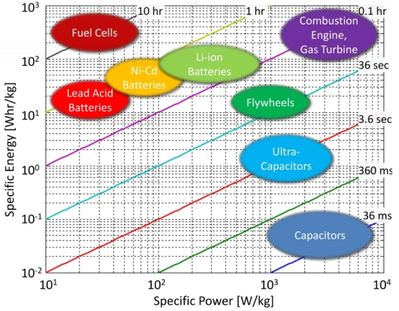
The vertical axis describes how much energy is available per unit mass (Energy density-Whr/kg), while the horizontal axis shows how quickly that energy can be delivered, otherwise known as power per unit mass (Power density- W/kg).
In the above plot, fuel cells have high energy density so that it can deliver small current for a long duration.
Among different types of batteries, lithium ion batteries have comparitively high energy density as well as power density which makes it suitable for automotive apllications.
whereas the ultracapacitors have high power density means it can deliver a large amount of current in a very short duration (typically in milliseconds). for this reason ultracapacitors are used to meet peak power requirement.