Week 2 Challenge
1. Estimate the line size for the following system
|
S.NO |
Composition |
Location |
Flow rate |
Pressure |
Temperature |
|
1 |
Water + Methanol (50-50 mol %) |
Pump suction |
15 m3/hr |
3 barg |
80°C |
|
2 |
Water |
Pump discharge |
10 m3/hr |
5 barg |
25°C |
|
3 |
Methane |
Compressor suction |
5 MMSCFD |
3 barg |
50°C |
|
4 |
Ethane- 0.3 mol% n-Pentane-0.2 mol% n-Hexane – 0.2 mol% n-Heptane-0.3 mol % |
Separator inlet |
1500 kg/hr |
5 barg |
100°C |
Solution:
Open Aspen HYSYS simulation software > file > new > case
Edit the component list and add all the components listed above.
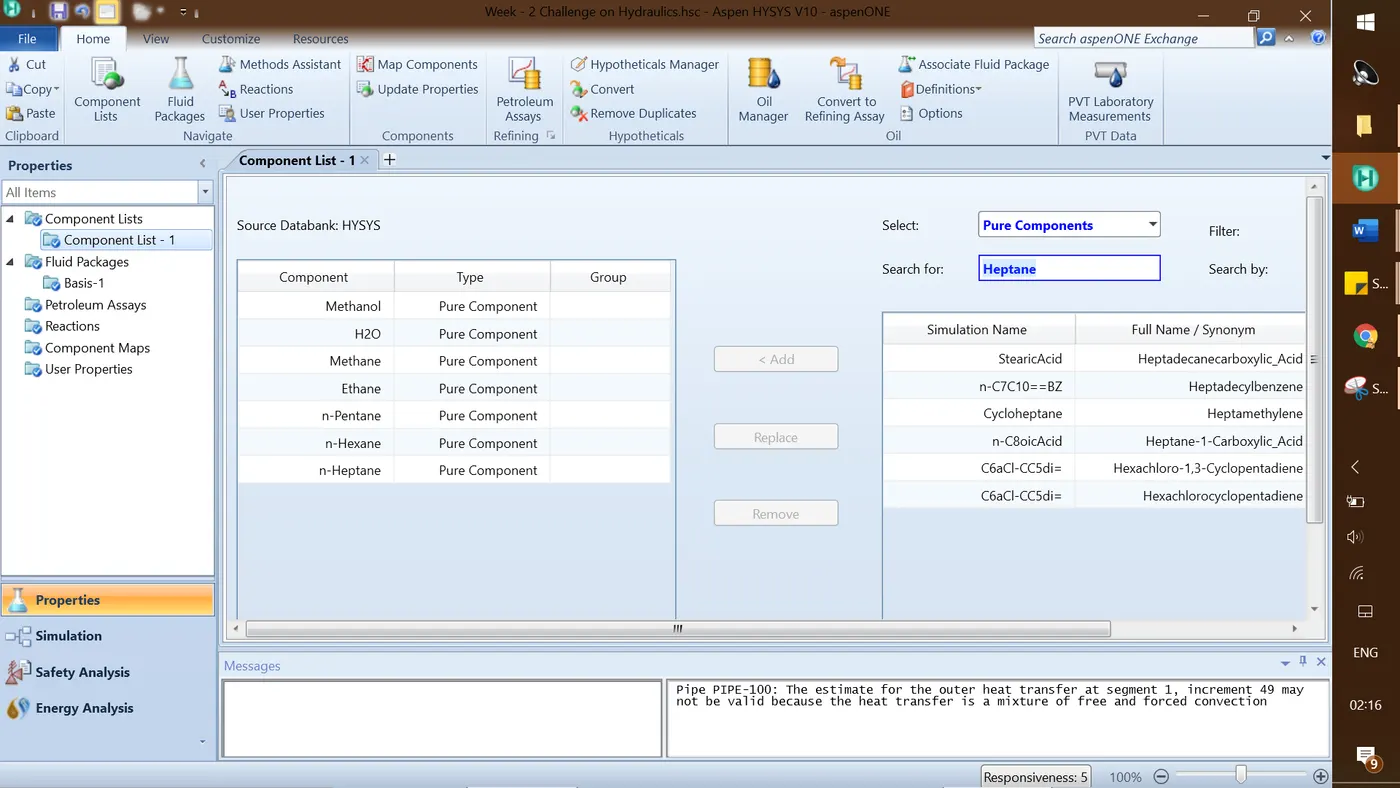
Next, select the property package as Peng-Robinson and click on the simulation page.
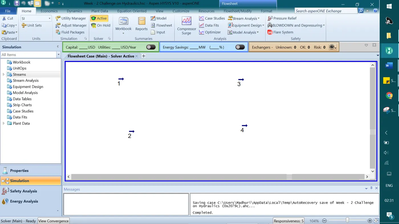
The streams named as 1, 2, 3, 4 should be converged first with the given conditions i.e. flowrate, pressure, temperature, and composition.
Estimating line size for the above streams – Once the streams are converged, go to Equipment Design > select line size option. However, the downloaded Aspen HYSYS V.10 in my computer has not got that ‘Line sizing’ option under equipment design.
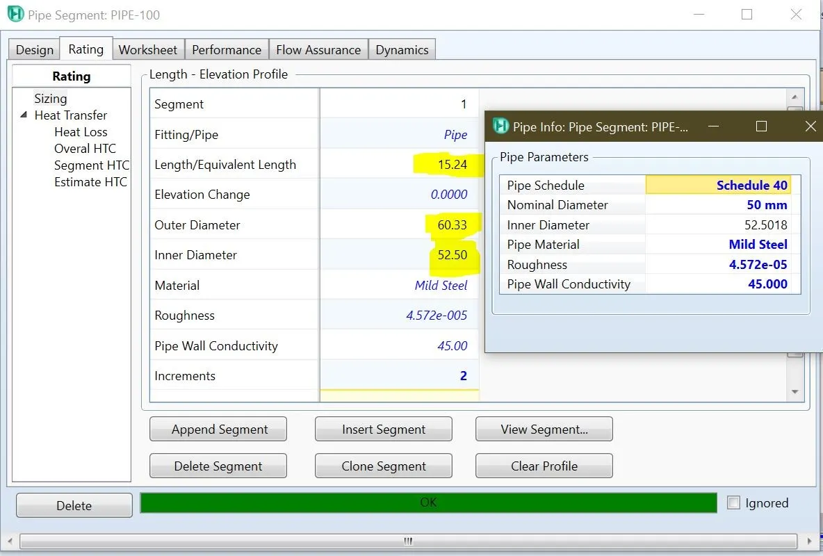
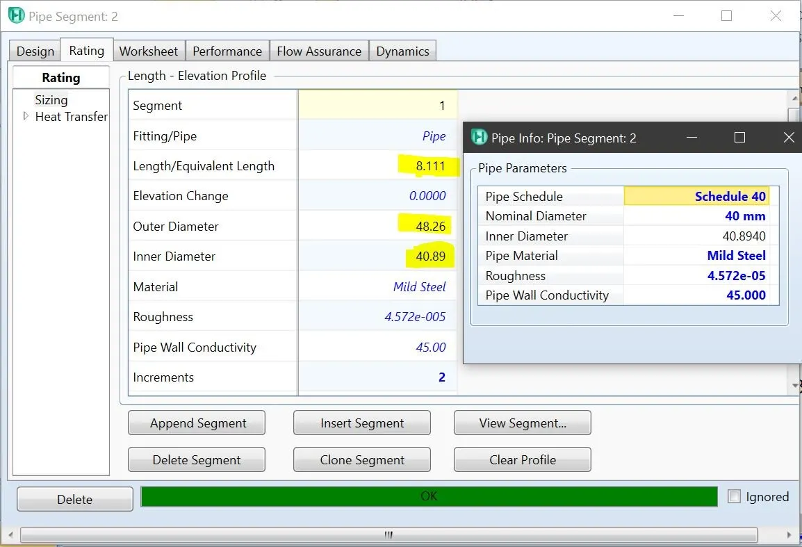
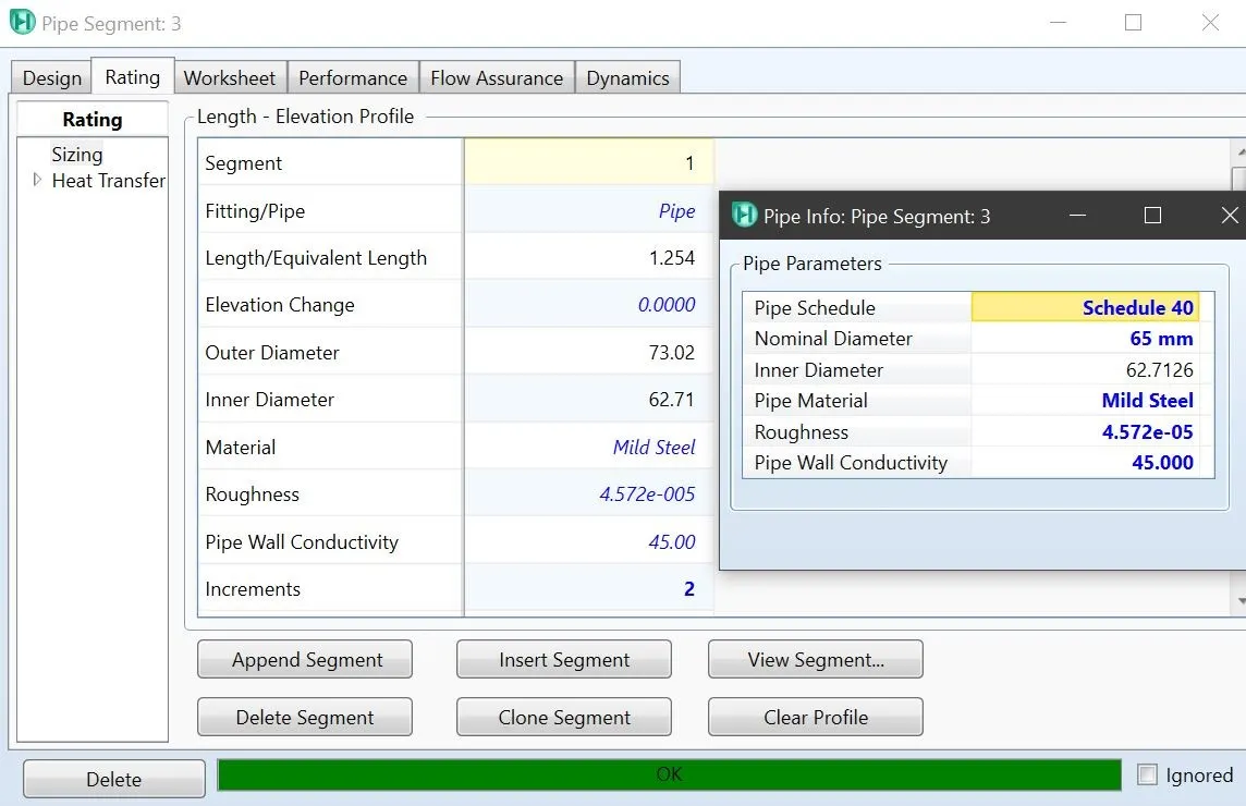
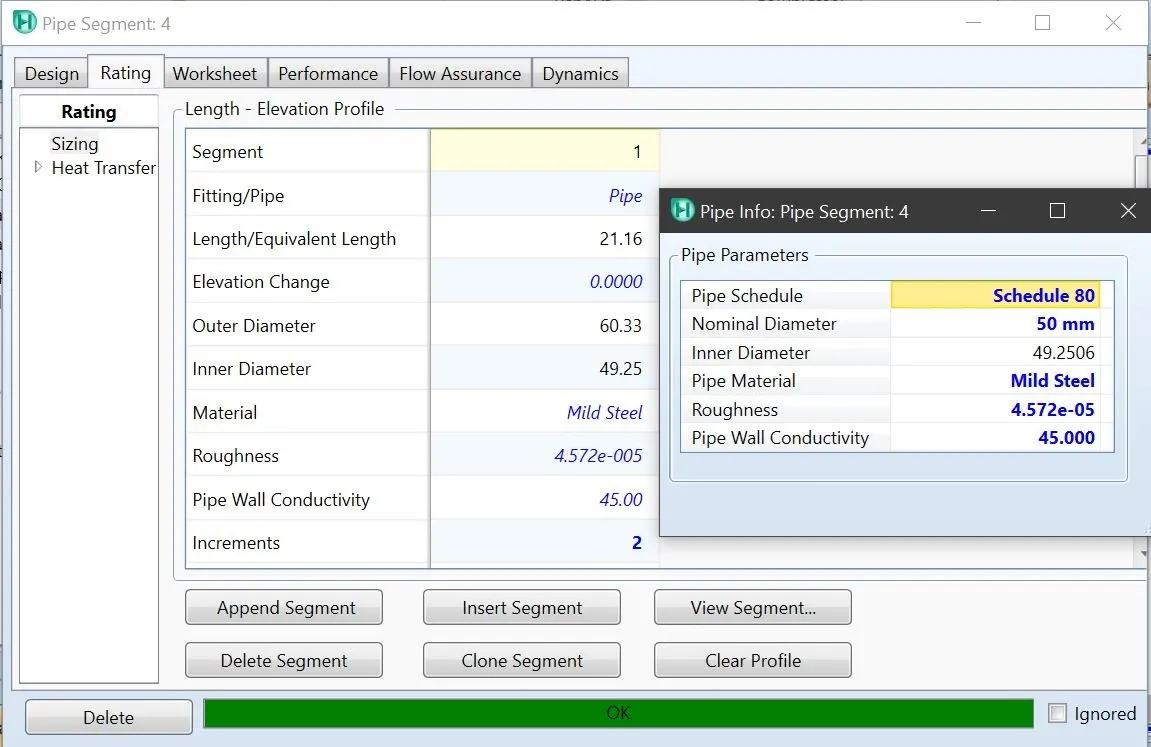
Hence, in this case, the pipe segment is used to calculate the required size (length of the pipe, outside and inside diameter) for the above conditions by providing a pressure drop value as 10kPa. Provide either Heat loss as 1000 kJ/h or ambient temperature as 30°C for the pipe heat transfer with the outside medium. If the ambient temperature is specified, then selecting ‘no insulation’ and taking air as an outside medium with wind velocity of 1m/s.
Pipe segments are added to each of the streams and 'Append the segment' option is added and provided the pipe material, schedule number, and nominal diameter. The pipes are now converged, and the results are as below.
S.No - 1:
S.No - 2:
S.No - 3:
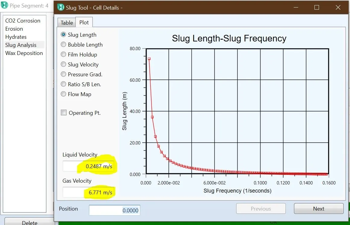
S.No - 4: The flow is 2-phase flow and the slug formation is occurred for the selected pipe sizes and given conditions.
2. Determine pressure drop for each of the above case based on the following pipe details
a. Pipe length – 50 m
b. Elevation change – 10m
c. Pipe material - stainless steel
d. Fittings
i. 90° elbow – 5
ii. 45° elbow – 4
iii. Flow thru run – 2
iv. Flow thru branch – 2
e. Ambient temperature – 40°C
f. Wind velocity – 6 m/s
Solution:
Following question 1 solution with the addition of pipe fittings, the pressure drop is calculated as:
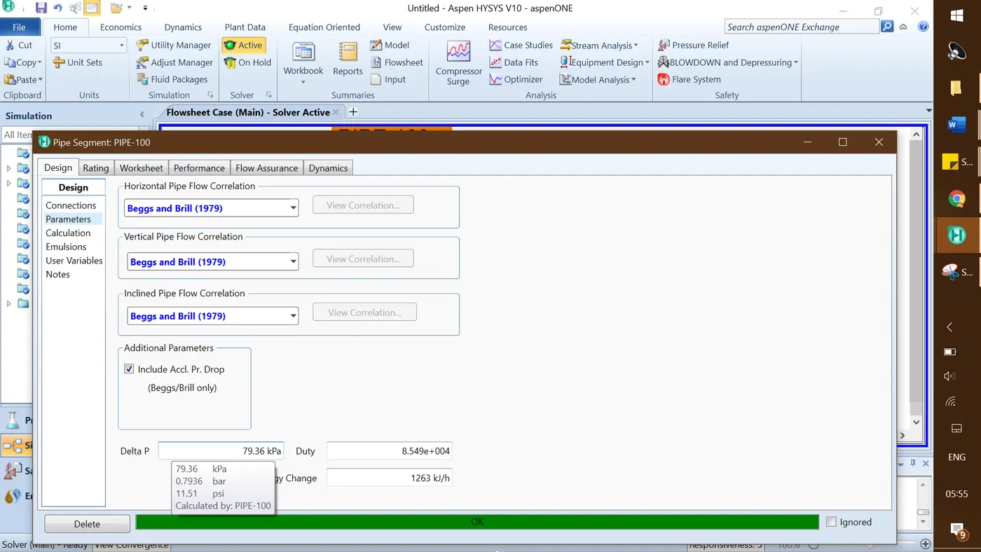
S.No - 1: The pressure drop is calculated as 79.36 kPa for pipe 100
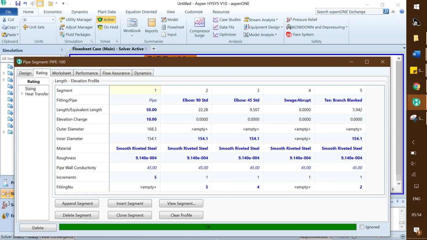
Pressure drop is shown in below screenshot for pipe-100
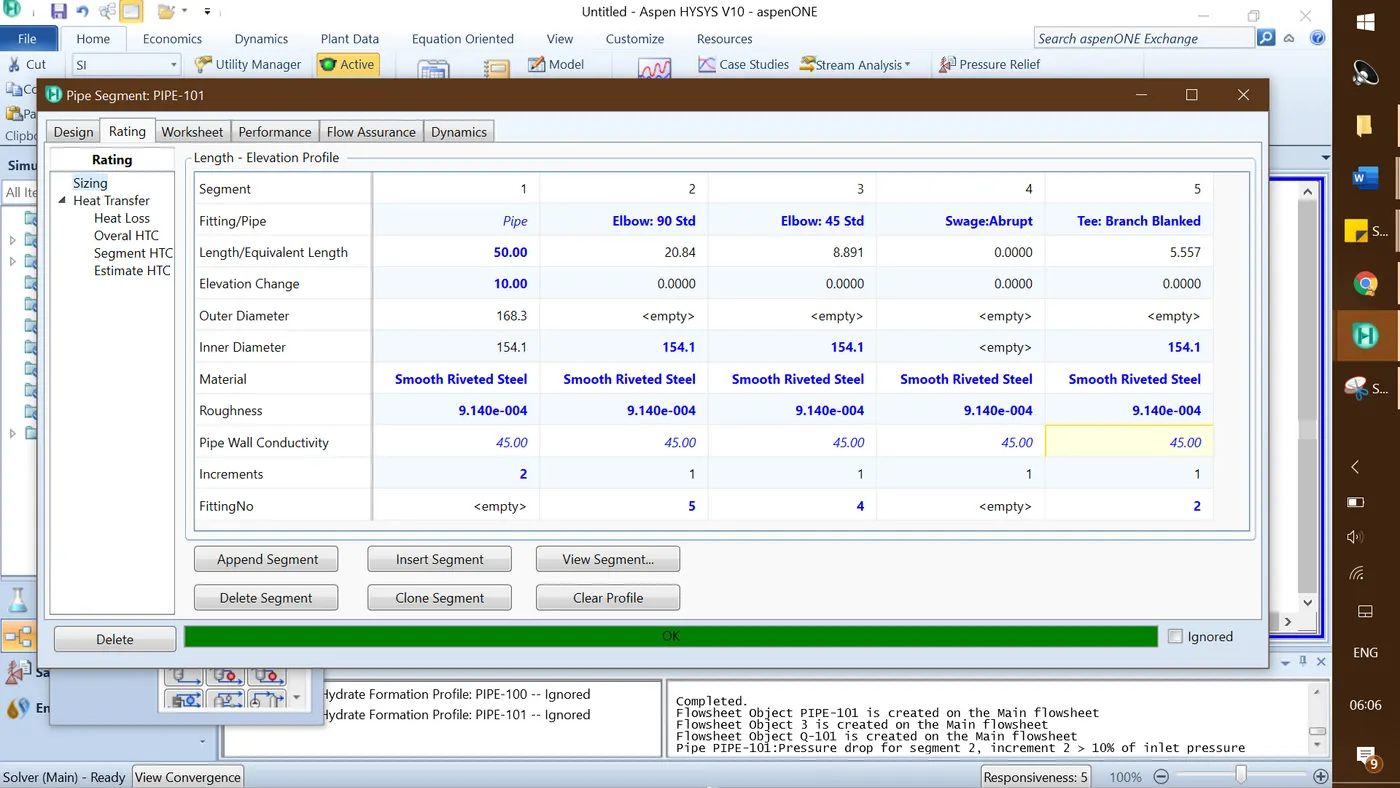
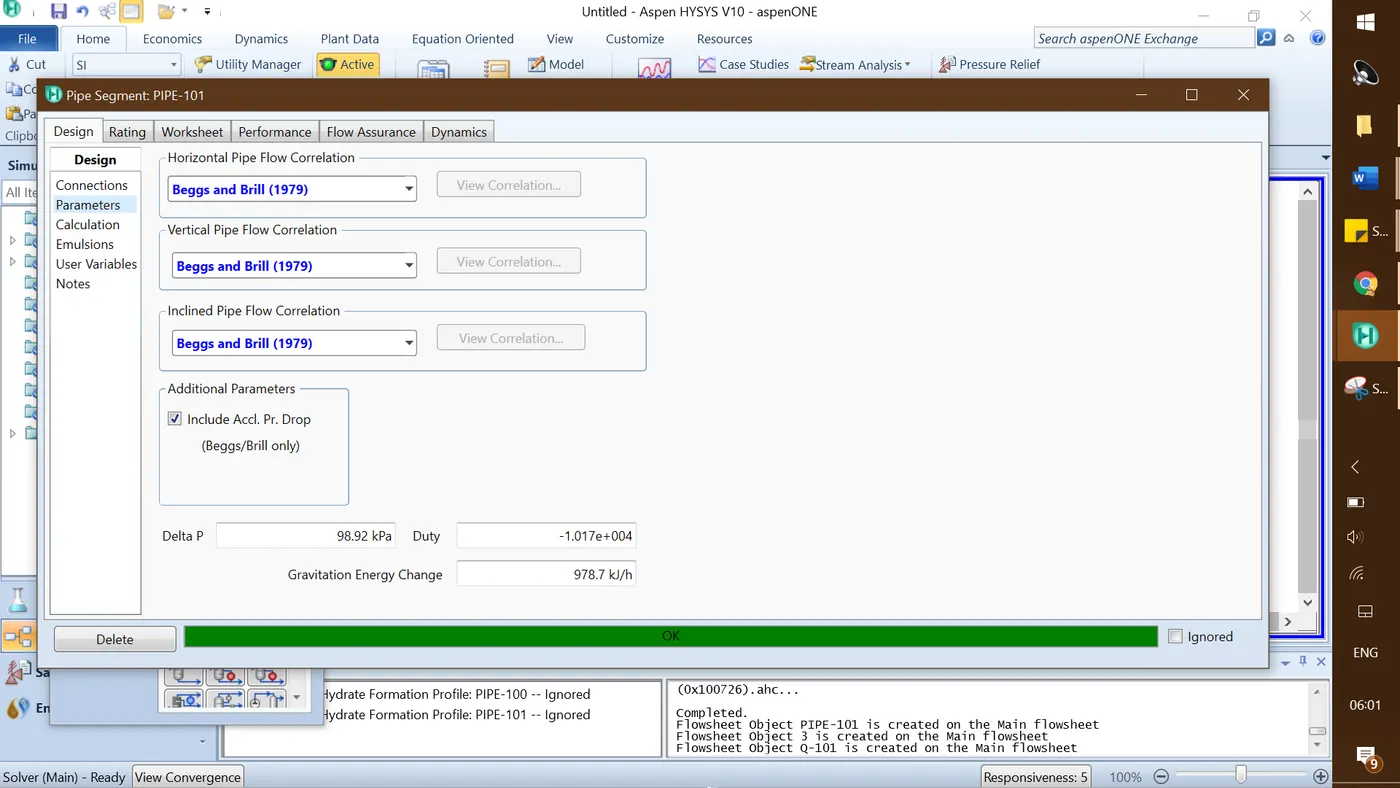
S.No - 2: The pressure drop is calculated as 98.92 kPa for pipe-101
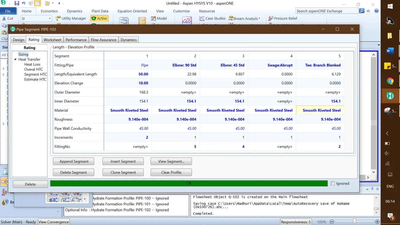
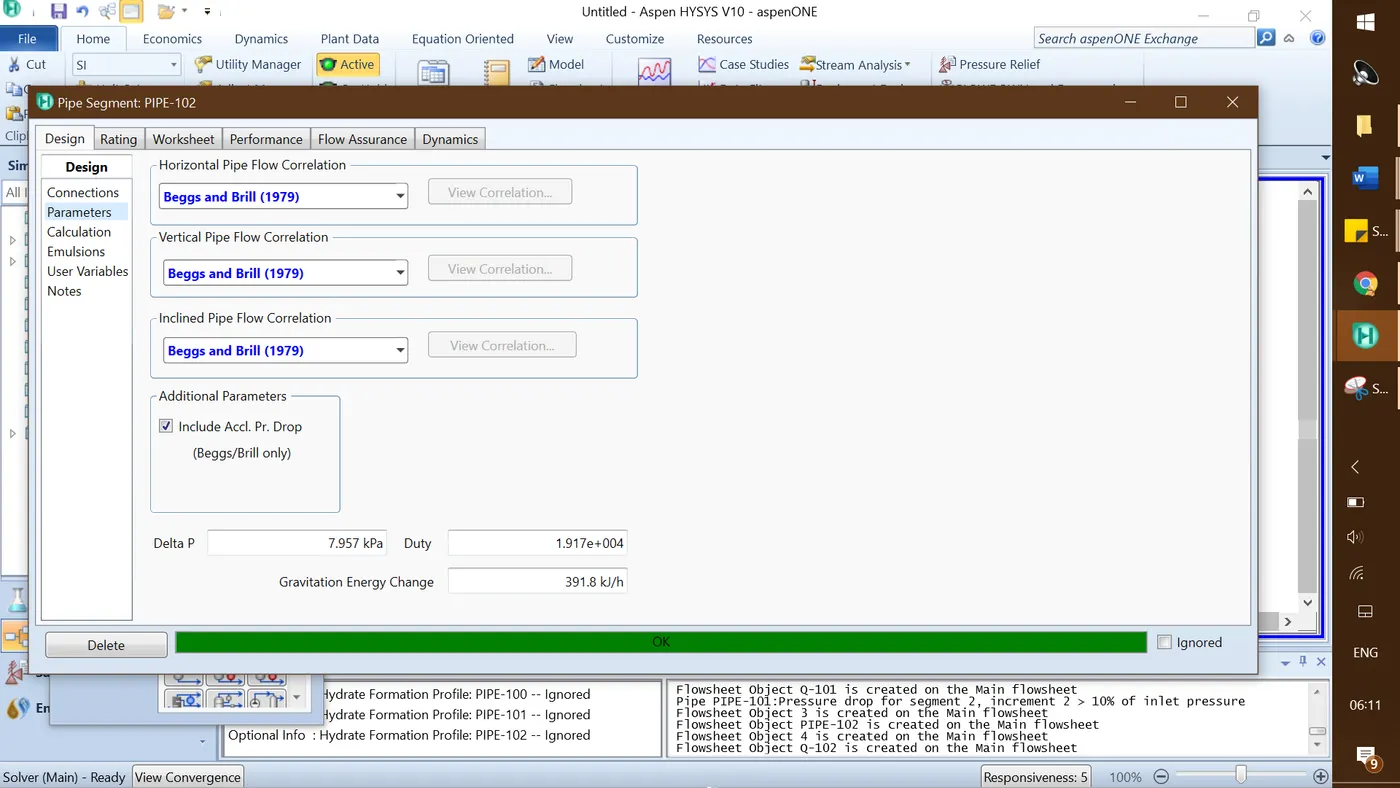
S.No - 3: The pressure drop is calculated as 7.957 kPa for pipe-102
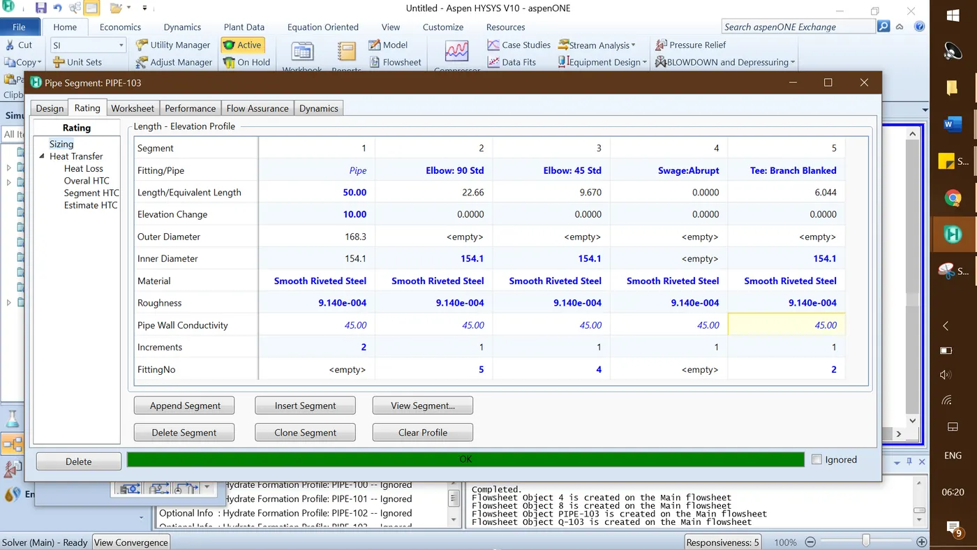
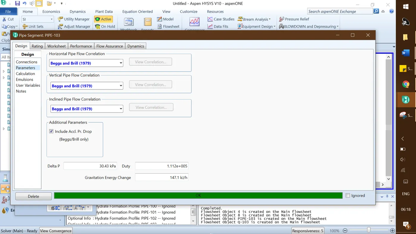
S.No - 4: The pressure drop is calculated as 30.43 kPa for pipe-103
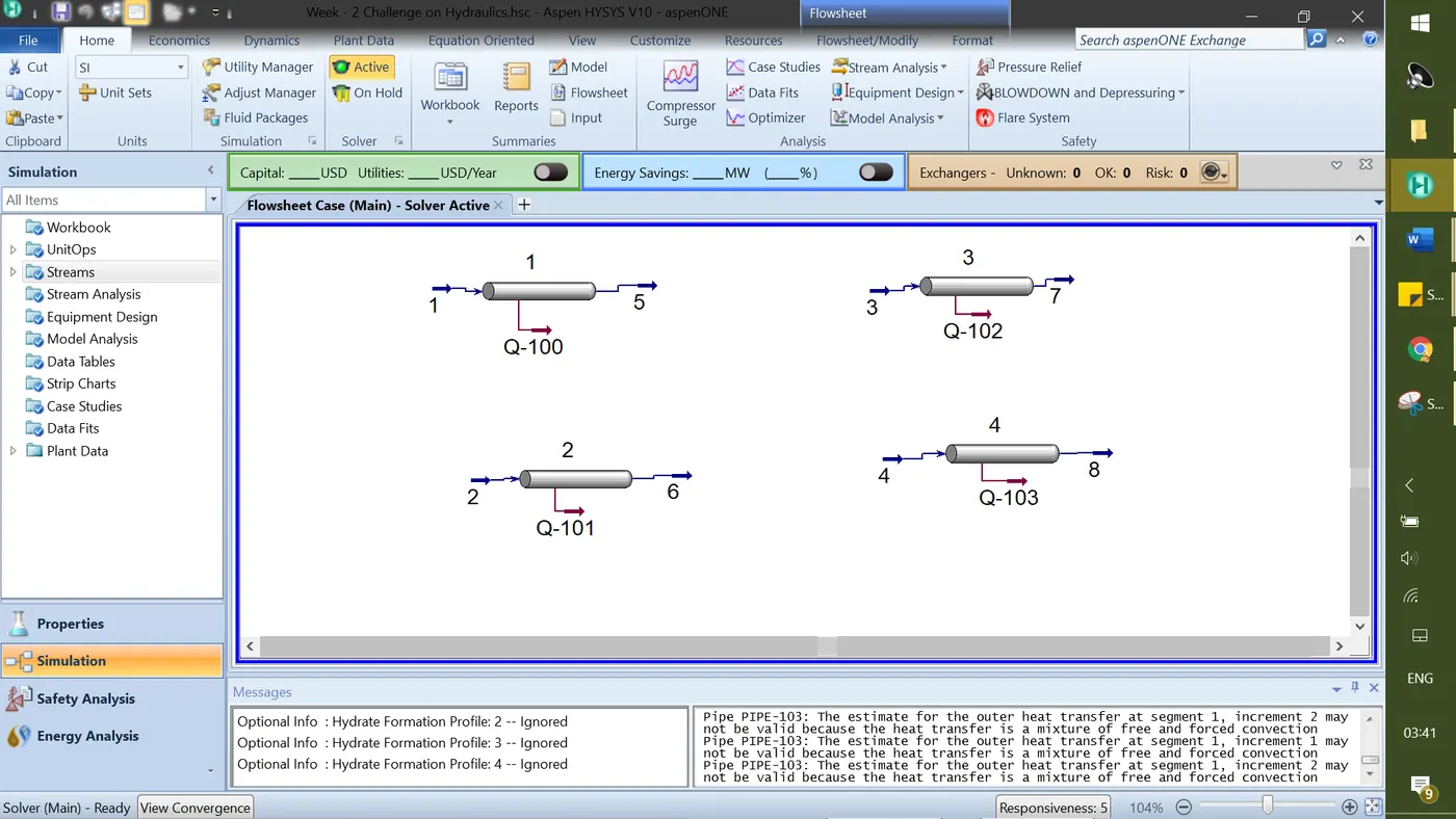
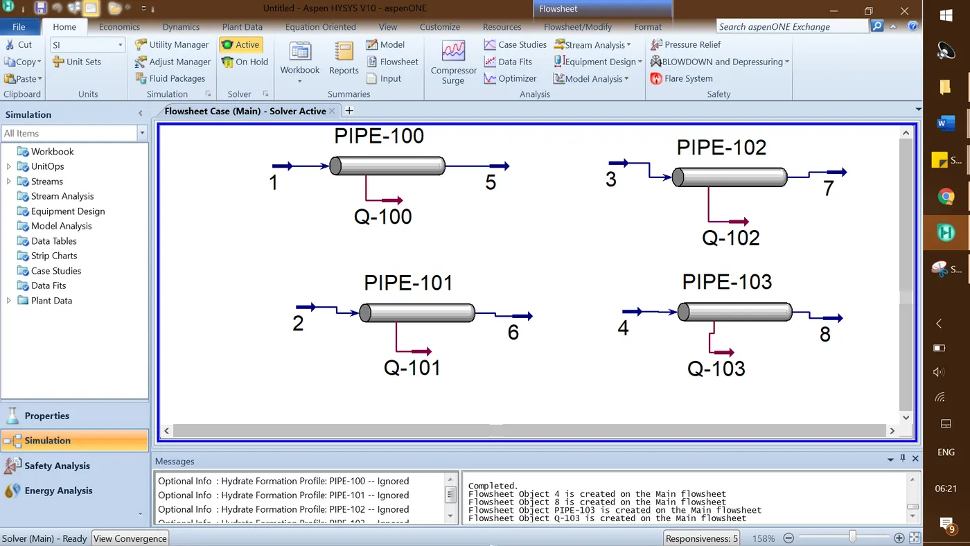
The simulation Process flow diagram for question 2 is shown below
3. Estimate NPSH available for the following
a. Pump flow rate – 6 m3/hr
b. Pumping fluid composition
i. Ethane – 0.016 mass frac
ii. N-pentane – 0.1663 mass frac
iii. N-hexane – 0.267 mass frac
iv. N-heptane – 0.5503 mass frac
c. Pumping condition
i. Pressure – 5 barg
ii. Temperature – 90°C
d. Pump suction details
i. Pipe size – 1.5 inch
ii. Pipe sch – 40
iii. Pipe length – 10m
iv. Elevation – 3 m
v. Low-low liquid level – 300mm
vi. Pipe material – carbon steel
vii. Pipe fittings
1. 90° elbow – 2
2. Ball valve – 1
3. Strainer loss – 5 psi
Solution:
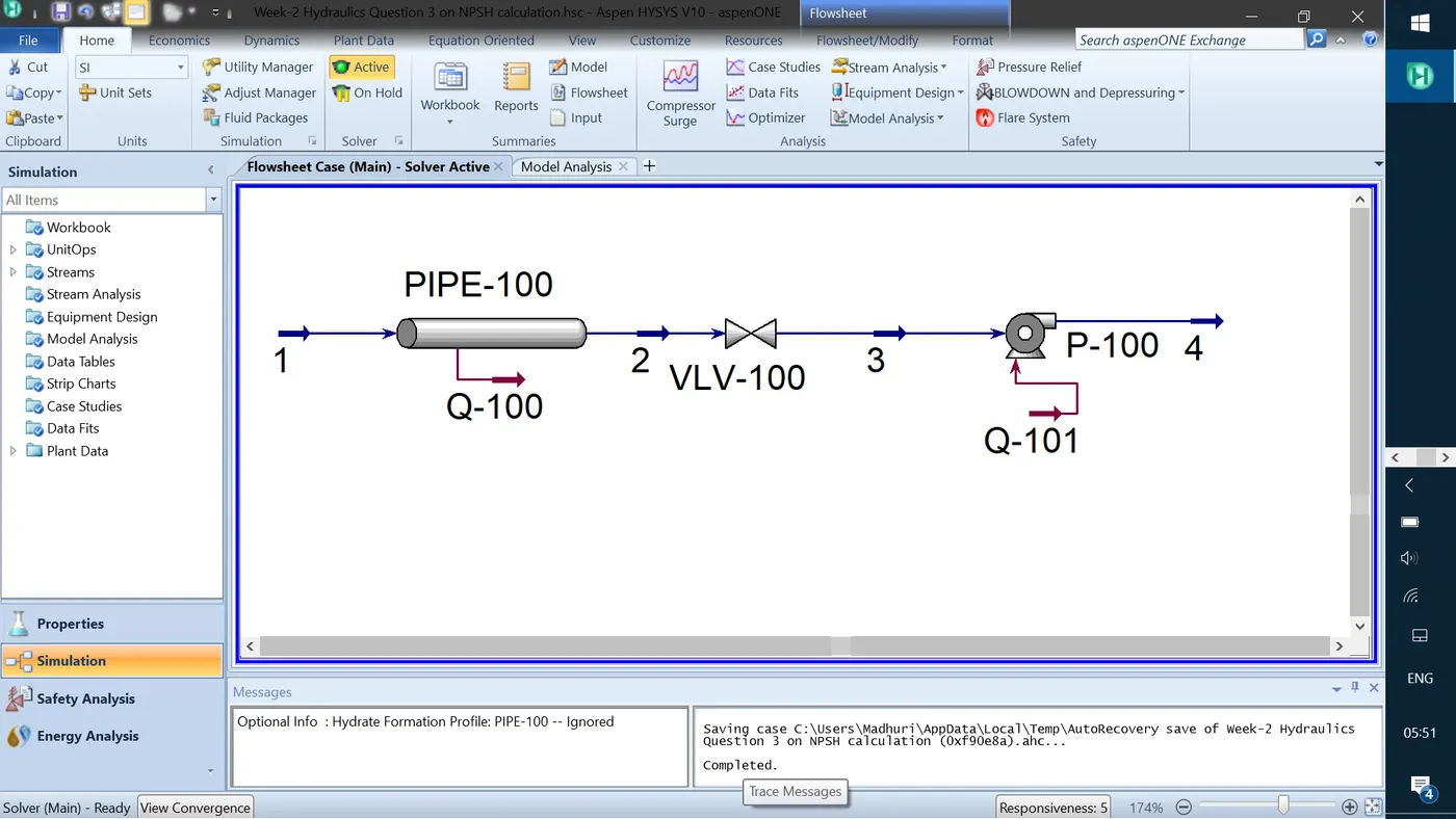
The simulation process flow diagram for question-3 is shown below. The control valve VLV-100 is used to introduce the strainer loss in the suction line.
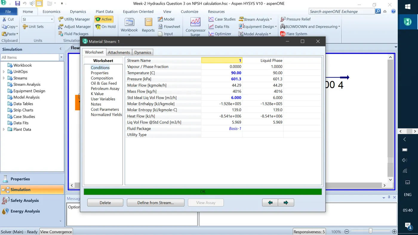
Stream-1 conditions are shown below. The vapour/phase Fraction with the given conditions is 0 which is in liquid state.
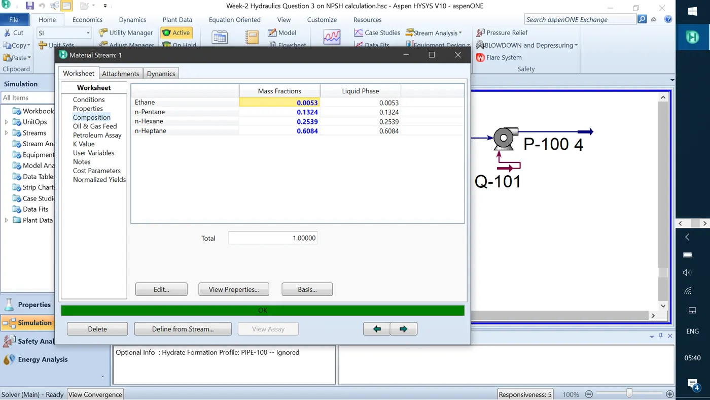
The composition for stream-1 is shown below
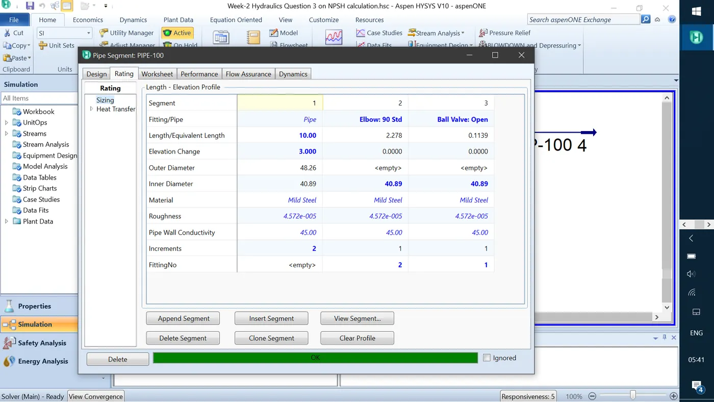
Pipe segments are added with the given fittings is shown below
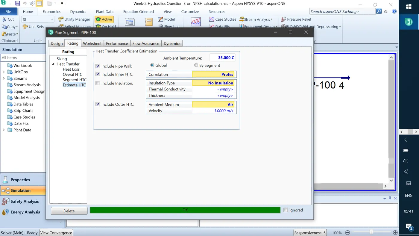
The ambient temperature is given to the pipe and the pipe is now converged with the calculated stream-2 conditions.
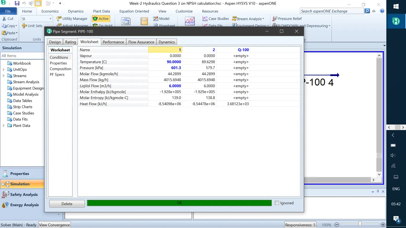
The calculated stream-2 conditions are shown below. The vapour fraction is still 0 which is in a liquid state.
To introduce the strainer loss of 5 psi, the control valve is used because of pressure drop input can be given with this valve option.
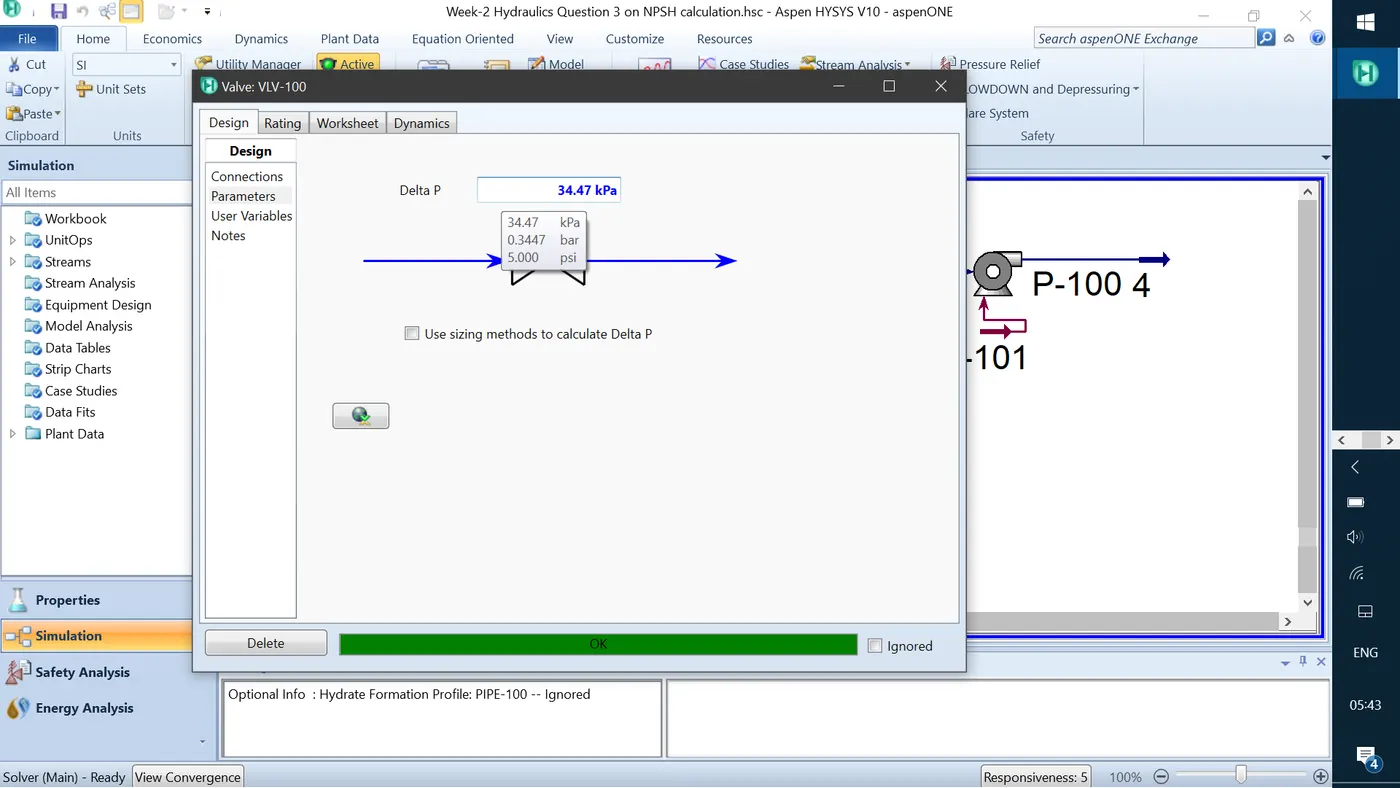
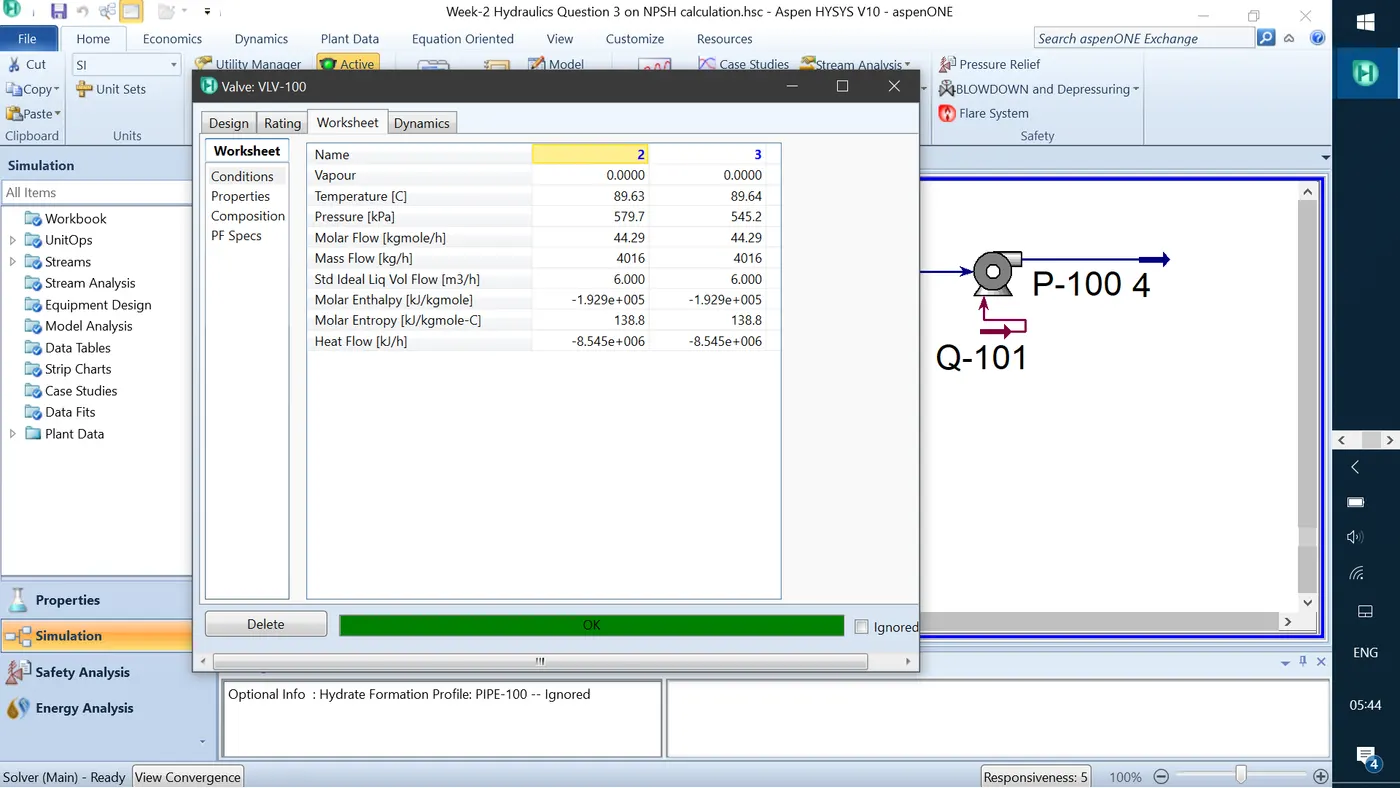
After the introduction of strainer pressure drop, the stream-3 conditions are shown below. It can be shown that the stream-3 is still in a liquid phase and the pump can be fitted to use this stream as an input to it.
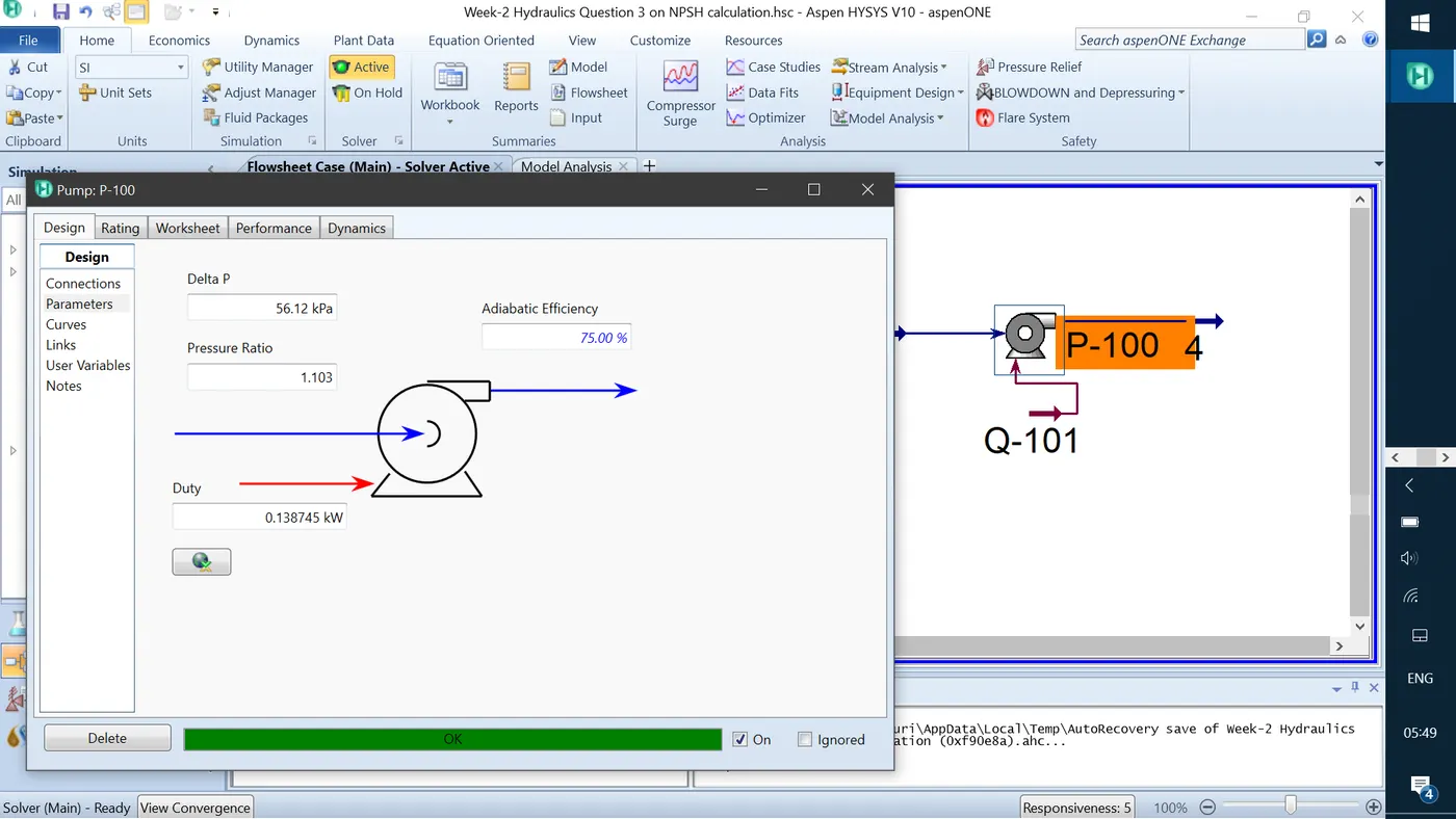
The pump P-100 is added with the adiabatic efficiency of 75%. The discharge pressure is given as 5 bar_g as an input in the stream-4 and the pump is now converged and calculated the pressure drop and the duty required in the pump.
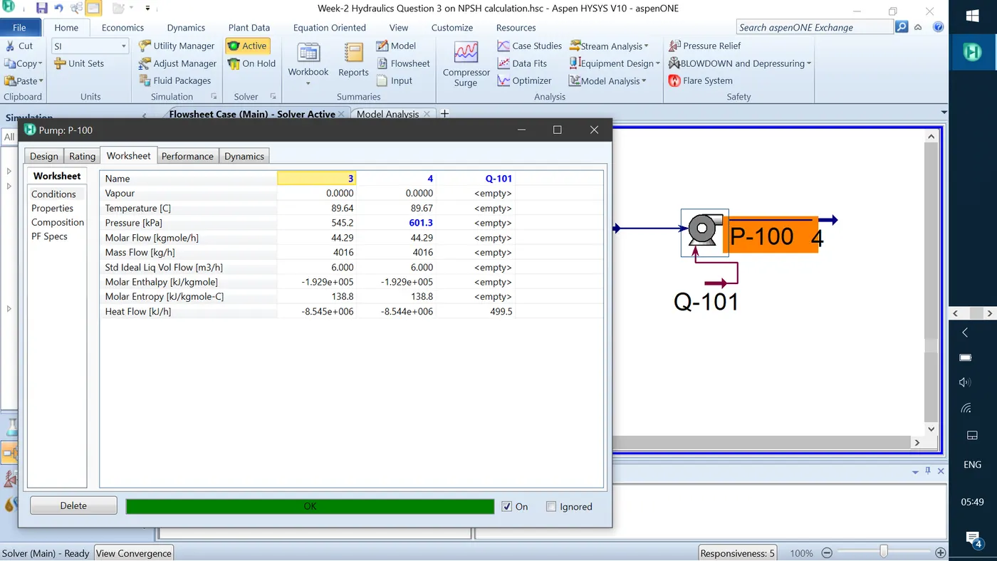
Suction and discharge stream 3 and 4 conditions are shown below.
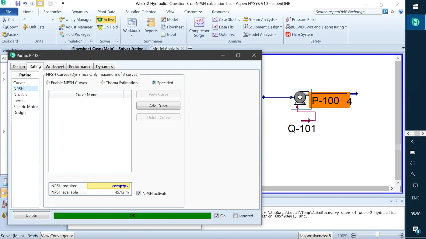
The NPSH required for the above conditions is calculated as 45.12 m.
4. Estimate the choked flow rate for the following conditions
- Pipe length – 50 m
- Pipe diameter – 2 inch sch 40 carbon steel pipe
- Ambient temperature – 35°C
- Wind velocity – 6 m/s
- Inlet pressure – 2 barg
- Outlet pressure – 1.6 barg
- Inlet stream temperature – 40°C
- Fluid water
Solution:
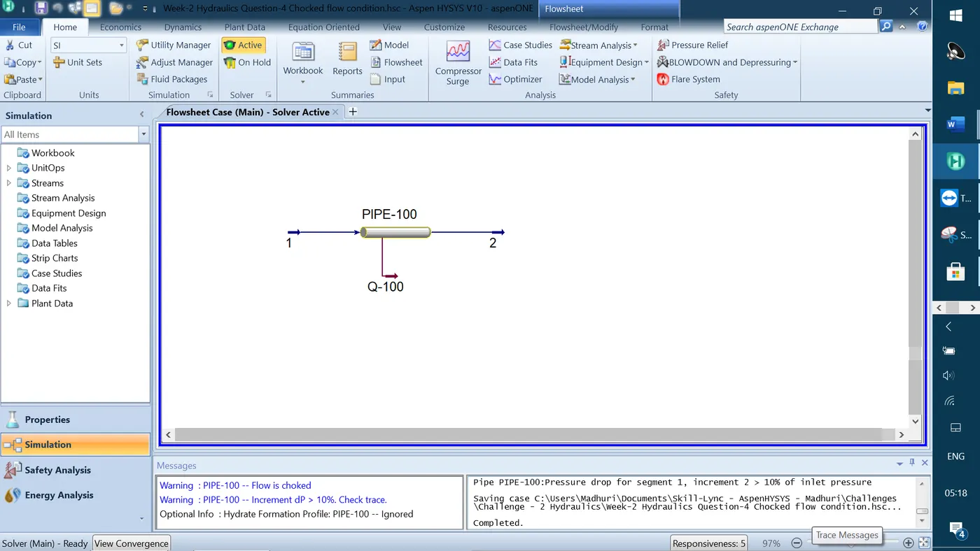
Simulation process flow diagram for question-4 is shown below.
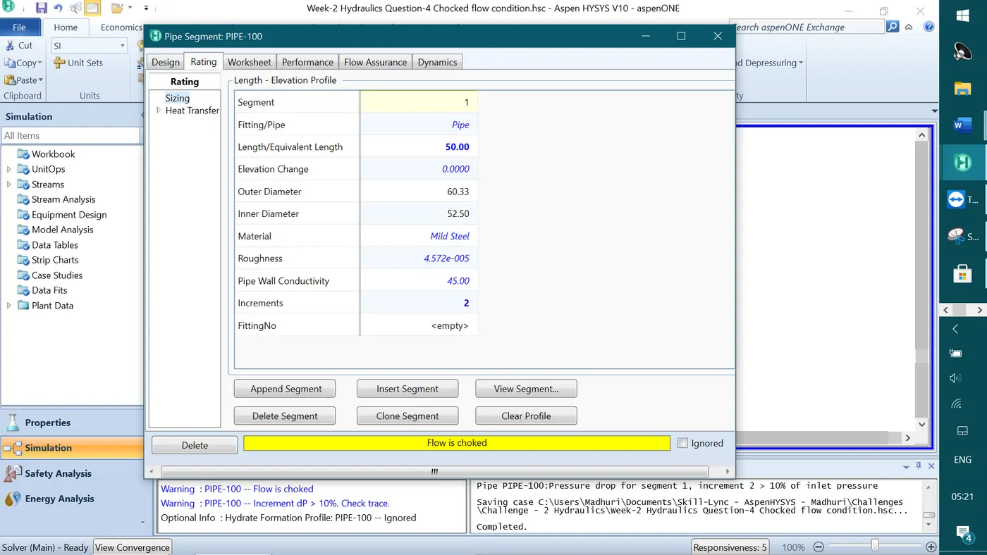
The pipe segment is added with the given fitting that is shown below
The conditions of the stream-1 & 2 are shown below. The initial guess for the mass flow is taken as 43350 kg/h. The warning sign of dp change can be seen in the below screenshot.
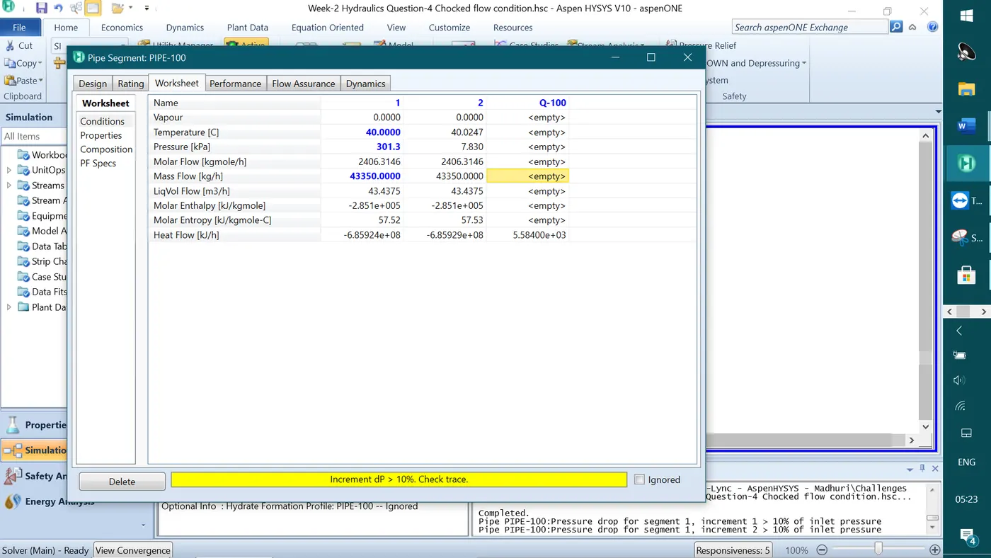
When the mass flow rate is slightly increased to 43400 kg/h the warning sign of 'Flow is Chocked' can be seen in the below screenshot. The chocked flow is defined as for specified pipe size when there is an increase in pressure difference, there is no further increase in the flow. i.e. the maximum possible flow rate for the specified pipe size.
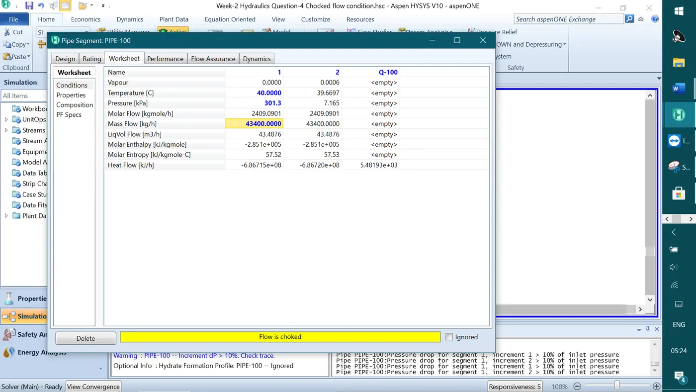
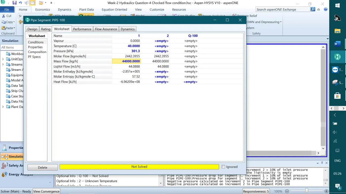
When the mass flow rate is increased to 44000 kg/h, the warning showed as 'Not solved' because the negative pressure is attained in the pipe discharge and the flow is not discharged outside of the pipe with the given pipe conditions. The chocked flow for the given pipe conditions is calculated as when the mass flow rate is in the range in kg/h is 43400 > Chocked flow < 44000.