Week 2:- BiW Fixture Basics Challenge
1. Project Execution Activity
The project execution phase is usually the longest phase in the project cycle and the most demanding. In the project execution phase:
- Your team carries out all the planned activities, constructs deliverables, and presents them to the project.
- Your focus, as a project manager changes to performing and supervising all activities to create deliverables as outlined in the project plan
- You’ll need to continuously track the project’s progress and ensure that the milestones and deliverables stick to the project schedule
- You need to step back a bit and let your team carry out the project plan
In project management, there might be hiccups along the way but if you catch them early on, it’s easy to course-correct. For this reason, the execution stage always happens in concurrence with the next phase project control monitoring
The majority of the activities during the execution phase will be handled by your project team. It’s a fine line to tread because you need to give your team enough autonomy while taking care that everything goes according to plan.
In essence, the project manager has three main objectives during the execution phase:
- Managing people
- Managing processes
- Managing communication
The benefits of a well-executed project are threefold:
- The project can be completed on time and budget
- Team morale can be maintained
- Stakeholders are satisfied with overall project progress
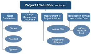
Project deliverables
Project deliverables are the tangible outputs of the project. They need to be reviewed, tested, and meet the acceptance criteria given by the clients.
Change requests
When client expectations change or there’s a disconnect between the team’s understanding of the client’s requirements, scope changes happen. These are documented in the change requests, which are then reviewed and approved.
Performance data
The execution stage produces a lot of data points that you can use to optimize your team’s performance. You can find where your team is spending most of their time with the help of the project dashboard and how you can cut down on time and costs.
Issue log
Whenever there are bugs, issues, or defects, you document them in the issue log. This will help you get back to the issues and fix them.
Documentation updates
Any changes to the documents created during the planning phase like the project scope and project schedule will be documented.
2. Joining processes:
1. Spot Welding
Spot welding is a thermal process in which metals are joined by heat generated by the resistance of electric current. In this workpieces(panels)are placed together under high pressure exerted by the electrodes. When a large amount of current is passed through the panels, current melts the panel on that specific spot where electrodes are touching the panel and forms a weld.
There are various guns to do spot welding but the most commonly used guns are X – TYPE and C – TYPE guns. X guns are also known as scissors or pinch guns. These guns are selected based on the location of the gun mount, tooling access, and the geometry of the panel. X-Gun or C-Guns can have different shapes of die posts as per the requirement.
The mentioned area is known as the die post of the gun.
X GUN :
In this gun, an actuator is parallel to the weld plane and actuates about a pivot.
X-type guns are used where accessibility is a constraint.
C GUN :
C-type or straight action gun actuates perpendicular to the plane and in line with the weld.
GUN STROKES :
Working Condition: That condition when both electrodes on the gun are touching the panel while doing spot welding is called a Working Condition.
Semi opening condition or intermediate stroke: After completing one stroke, the gun moves to the next spot without opening completely is known as intermediate stroke or semi opening. This opening may differ as per the requirement.
Full Stroke or Full opening: it is the maximum open condition of moving electrodes of the gun.
Basics while considering a gun :
- Preferably Fixed electrode should be visible to the operator.
- Gun should have good reach-ability to all spots.
- As much as the possible same gun should be used for maximum no. of spots.
- Tip wear-out condition (preferably 5 mm) should be considered while designing the tool.
Self piercing Rivet(SPR) :
SPR- Self-piercing riveting is a cold mechanical fastening technique for the joining of two or sheet metals or panels. For joining, the rivet is driven into the metal at a controlled force, piercing the panels, Then the rivet radially expands into the bottom layer, due to the shape of the die, forming a mechanical interlock.
This process is quite helpful in joining aluminum panels.
MIG WELDING(Metal Inert Gas) :
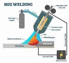
Metal inert gas welding or MIG Welding is based on the electric arc welding process where completion of an electric circuit between positive and negative poles creates an electric arc, which generates tremendous heat permitting the fusion welding of metals.
GLUE GUN :
Glue guns are used for metering sealants or adhesive bonds.
adhesive bonding and sealing are used for various applications in the modern automotive industry.
3. Resistance welding
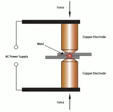
Resistance welding is generally used to join two plain metal workpieces together. An electric current is delivered to the metal sheets (or any workpieces being joined) through weld electrodes which apply force to the sheets. This force is then converted to heat. The heat is generated so that it melts the metal at the point where they join – the point of ‘resistance’ between the faying surfaces. The electrode then extracts heat from the molten weld area which forms a weld nugget at the point where it solidifies. A force is applied before, during, and after a current is applied, which confines the contact area.
Types of Resistance Welding
There are many resistance welding processes with different uses, such as spot welding, seam welding, and butt welding. Each one has a different specific welding application that makes it optimal for a particular situation.
1. Resistance Spot Welding
Resistance spot welding has been used extensively in the automotive industry for the joining of steel and in the aerospace industry for airframe components made from aluminum alloys. It is one of the oldest and simplest forms of resistance welding, in which a weld nugget is produced by passing an electric current between the two metal components whilst they are held together between electrodes, typically made from copper-based alloys due to their superior conductive properties.
2. Resistance Seam Welding
Resistance seam welding is a variation of the standard spot welding form, however, instead of spot one nugget, a series of overlapping nuggets is produced. This is usually done by replacing the conventional spot welding electrodes with wheels, which turn as the parts are fed between them. The process thus produces a continuously welded seam rather than a single spot. Seam welding is often used in the production of thin sheet, leak-tight containers such as fuel tanks, and is generally unsuitable for welding aluminum.
3. Resistance Projection Welding
Resistance projection welding is a form of resistance welding where the electricity, force, and weld time are concentrated on raised ‘projections’ across the surface. Projection welding is generally used for welds using thicker materials than the thinner metal pieces that spot welding is usually required for, and often not metals. It is used primarily in the electrical, automotive, and construction industries.
4. Resistance Butt Welding
Resistance butt welding is a process in which the two components of a similar cross-section can be joined together in one operation that takes place simultaneously across the entirety of the affected object, rather than just in small spots. The welding application of butt welding is often in wires and rods with small diameter measurements, generally up to about 16mm diameter.
5. Flash Butt Welding
Flash butt welding is similar, but in this case, the energy transfer is primarily provided by the resistance heat arising from the parts themselves. This is a faster type of resistance welding where the welder joins the parts by applying some pressure, then bypassing a heavy current through the joint which burns away surface irregularities. After the weld has generated enough heat, the parts are connected by applying heat and pressure simultaneously. This produces a forge butt weld with no melted metal remaining in the joint.
4. fusion welding
Understanding different types of fusion welding processes are critical when discussing fusion welding. Based on the heat source, fusion welding processes can be categorized as follows:
1. The Arc Welding Process
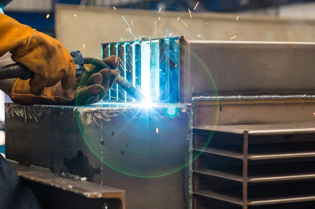
Arc welding is among the preferable ways of a fusion welding process. True to the hype, arc welding connects two parts (or more) using an electric arc. The reason is that electric arcs generate heat levels that reach up to 6,000 degrees Fahrenheit, making them ideal for fusing hard metals and materials. Additionally, arc welding is also suitable for offshore applications where you can perform underwater fusion welding. Commonly, arc welding processes include:
2. Laser Beam Welding (LBW)
As the name suggests, this is a fusion welding process that uses a focused laser beam as its energy heat source. The high heat levels have precision rates useful for joining metals and polymers. It is a fast and automated process that uses light to generate heat.
You can perform an LBW in the air instead of a vacuum, unlike the electron beam fusion welding processes.
3. High-Energy Welding Processes
It is a fusion welding process that produces heat through light radiation. To fuse the different materials, you blast the radiation light to the materials’ surface, making them become hot and start to melt. The workpiece will later merge as they gradually cool down.
These are typical examples of high-energy fusion welding processes.
4. Electronic Beam Welding (EBW)
The electronic beam welding process involves high-velocity electrons to join workpieces together. The electrons produce intense heat that enters the materials changing their solid state to molten. EBW welds are deep and thin and can only be achieved under specific atmospheric conditions.
5. Friction Welding
When applying the friction welding technique, the different materials are joined together using mechanical friction. There are various ways to perform mechanical friction on aluminum, steel, and sometimes wood materials.
The process of mechanical friction is arduous. However, the heat you generate will soften both materials, creating a bond after mixing and cooling afterward.
There are various ways to perform friction welding, which determines the kind of joints you will have. These processes include:
6. Resistance Welding Processes
It is among the fastest fusion welding options you can apply, making it a preferable choice for the automotive industry. Today, there is two resistance welding process. These are:
Resistance spot welding
It works by producing heat on two electrodes. However, the bonding process depends on the properties and thickness of the materials. The process confines the welding voltage to a single spot when fusing the different workpieces.
Resistance seam welding
It is a form of spot welding that includes a sequence of joint-alternating nuggets. It uses shifting disks to replace the spot welding electrodes to join the materials together.
5. What is the 3-2-1 principle?
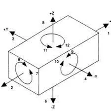
The 3-2-1 principle
Locating a part to be machined involves mainly three steps: Supporting, Positioning, and Clamping.
Two main intentions when placing a job on a jig/fixture are:
- Precisely positioning the part at the desired coordinates.
- Curbing all six degrees of movement so that the part cannot budge.
An extensively used method for obtaining these objectives is the 3-2-1 principle or six degrees of freedom for part location.
The 3-2-1 method is a work-holding principle where three pins are located on the 1st principle plane, i.e., either XY, YZ, ZX. And two pins are located on the 2nd plane perpendicular to the 1st plane, and at last, one pin on the plane is mutually perpendicular to the 1st and 2nd planes. The aim is to constrain the movement of the workpiece along all three axes.
Design objectives of Jigs and Fixtures
Before sitting down to design jigs/fixtures, the designer must consider the following points:
- The tool must be foolproof to prevent any mishandling or accidental usage by the operator.
- Easy to operate for increasing efficiency.
- Easy to manufacture using the lowest costs.
- Its ability to weather the tool life instead of appropriate materials.
- Must be consistent at producing high-quality parts.
- Must be safe and secure to use.
The designer must know the basics of the process and the tools associated with it for which the jig/fixture is designed. Overall objectives to look out for a while developing such tools are:
- Cycle time.
- Type of Jig/Fixture.
- Part Assembly sequence or Machining locations.
- Joining or machining process.
- Clamping method and clamping sequence.
- Required output accuracy.
- Type of equipment to be used with the jig.
- Method of ejecting finished output and transferring it to the next. Platform, whether the manual or automatic mode.
- The type of material, recommended weight, number of spots involving welding.
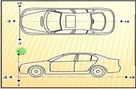
6. Body coordinate system
Definitions
The blocks use right-handed (RH) Cartesian coordinate systems. The right-hand rule establishes the x-y-z sequence of coordinate axes.
An inertial frame is a nonaccelerating motion reference frame. In an inertial frame, Newton's second law holds force = mass x acceleration. Loosely speaking, acceleration is defined concerning the distant cosmos, and an inertial frame is often said to be nonaccelerated concerning the fixed stars. Because the Earth and stars move so slowly concerning one another, this assumption is a very accurate approximation.
Strictly defined, an inertial frame is a member of the set of all frames not accelerating relative to one another. A noninertial frame is any frame accelerating relative to an inertial frame. Its acceleration, in general, includes both translational and rotational components, resulting in pseudo forces (pseudo gravity, as well as Coriolis and centrifugal forces).
The blocks model the Earth shape (the geoid) as an oblate spheroid, a special type of ellipsoid with two longer axes equal (defining the equatorial plane) and a third, slightly shorter (polar) axis of symmetry. The equator is the intersection of the equatorial plane and the Earth's surface. The geographic poles are the intersection of the Earth's surface and the polar axis. In general, the Earth's polar and rotation axes are not identical.
Latitudes parallel the equator. Longitudes parallel the polar axis. The zero longitude or prime meridian passes through Greenwich, England.
Approximations
The blockset makes three standard approximations in defining coordinate systems relative to the Earth.
-
The Earth's surface or geoid is an oblate spheroid, defined by its longer equatorial and shorter polar axes. In reality, the Earth is slightly deformed concerning the standard geoid.
-
The Earth rotation axis and equatorial plane are perpendiculars so that the rotation and polar axes are identical. In reality, these axes are slightly misaligned, and the equatorial plane wobbles as the Earth rotates. This effect is negligible in most applications.
-
The only noninertial effect in Earth-fixed coordinates is due to the Earth's rotation about its axis. This is a rotating, geocentric system. The blocks ignore the Earth acceleration around the Sun, the Sun acceleration in the Galaxy, and the Galaxy acceleration through the cosmos. In most applications, only the Earth rotation matters.
This approximation must be changed for spacecraft sent into deep space, such as outside the Earth-Moon system, and a heliocentric system is preferred.
Motion concerning Other Planets
The blockset uses the standard WGS-84 geoid to model the Earth. You can change the equatorial axis length, the flattening, and the rotation rate.
You can represent the motion of spacecraft concerning any celestial body that is well approximated by an oblate spheroid by changing the spheroid size, flattening, and rotation rate. If the celestial body is rotating westward (retrogradely), make the rotation rate negative.
Coordinate Systems for Modeling
Modeling aircraft and spacecraft are simplest if you use a coordinate system fixed in the body itself. In the case of aircraft, the forward direction is modified by the presence of wind, and the craft moving through the air is not the same as its motion relative to the ground.
See Equations of Motion for further details on how the blocks implement body and wind coordinates.
Body Coordinates
The noninertial body coordinate system is fixed in both origin and orientation to the moving craft. The craft is assumed to be rigid.
The orientation of the body coordinate axes is fixed in the shape of the body.
-
The x-axis points through the nose of the craft.
-
The y-axis points to the right of the x-axis (facing in the pilot's direction of view), perpendicular to the x-axis.
-
The z-axis points down through the bottom of the craft, perpendicular to the XY plane and satisfying the RH rule.
7. Body plane system & its essentials
Body planes are three mutually perpendicular imaginary planes. These are reference planes in the automotive car. These are used to define the GD & T of all parts in the automotive domain.
- The measurement from body plane to parts is called body plane dimensions.

- Bodylines dimensions are essential for the below reason
- It defines the exact position of each product in the vehicle w.r.t a fixed origin.
- It ensures flawless design for assembly.
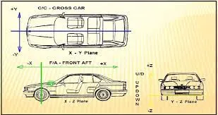
- While designing lines, all the designs are carried out relative to the bodylines viz. fixtures, Turntables, etc.
- It assists in the easy location of different parts in the vehicle.
- It aims in creating a standardized system.
- It assists in quality checks