Week 2:- BiW Fixture Basics Challenge
1.What is the process of project execution activity ?
Following steps are involved in the project excution activity.
- Request for Quotation Recieved : Customer gives requirement /specification in the form of documents and data.
Also Customer gives the timeline of project execution and technical criteria like standards to be followed like NAAMS & commercial standards to be used. - 1st Spec Discussion Meeting :After RFQ received there will be discussion with the customer where project standards and guidelines are discussed.Approximate Timeline is discussed.
- Offer Submission :
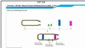
Example for Fixture to be modified for full robotic welding consideration of child parts.
Design & detailing : 15hrs
Simulation activities : 4 hrs
Parts to be manufactured : Turnion frame, 12-15 Blocks
Brought out list : Motor, Gear Box, Cylinders, Sensors, Electrical Fittings.
Assembly,Installation & Commissioning : 15-16Hrs.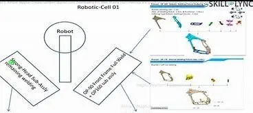
Simulation activities : 4 hrs
Parts to be manufactured : Turnion frame, 12-15 Blocks
Brought out list : Motor, Gear Box, Cylinders, Sensors, Electrical Fittings.
Assembly,Installation & Commissioning : 15-16Hrs.
Design activity planning for New Fixture.
Design & detailing : 30hrs
Simulation activities : 5 hrs
Parts to be manufactured : Base & 20-25 BlocksBrought out list : 2-3 cylinder ,electrical fittings
Assembly,Installation & Commissioning : 10-12 Hrs.
Design activity planning for New Fixture.
Design & detailing : 70hrs
Simulation activities : 10 hrs
Parts to be manufactured : Base & 90-100 Blocks
Brought out list : 8-10 cylinder ,electrical fittings
Assembly,Installation & Commissioning : 40-45 Hrs.
Shown above are Technical Offer. Based on this tentative commercial offer will be submitted. - LOI/PO Recipt : Customer will study offer & compare it with the offer recieved from other vendors.After evaluvating customer will release the Purchase Order(PO). Along with this we get input data from customer Examples :- Car panel 3D models,Design Standards, Manufacturing Standards, 3D standards, 2D standards Etc.
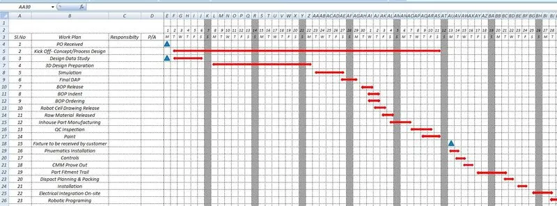
- Schedule Preparation :
- BOM Preparation: We prepare required cylinders, fittings etc in the BOM.
- Design Concept Preparation :
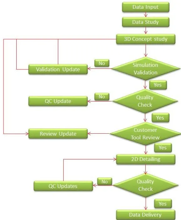
- Customer Approval Process or Design Approval Process : Customer will review the design whether it meets their standard after that he will indicate the changes like if more sensors need to be added etc. Once he is satsified he will approve the design.
- Detailing & Drawing Release : After 3D approval 2D drawings are done and released to manufacturing.
- Manufacturing & BOP ordering : Parts are manufactured and Order for commercials are released.
- Quality Inspection : Manufactured Parts are checked for errors before assembly so as to save time and cost.
- Mechanical/Electrical Assembly : As per design Assembly will be done.Once completed QC will done with help of CMM to check for pin position , clamp position etc.
Once it passes the test approval will be given. - Internal Trail/Testing : We place the panel assembly in the fixture and look for correct positioning of panel whether pins are locating correctly and clamping is proper. Also Welding Gun accesability is checked.
- Online Trail : In online trail everything done through control panel , sequencing is checked.Once customer approves online trail we do proper packaging of fixture to send it for installation & commisioning.
- Dispatch :
- Installation as per layout : The layout will be designed at the intial level showning the position of robots along with the fixtures.
- Trails and Training at customer : Production trial is done to check whether given fixture can produce final components to meet the required standards , Production Quantity is met. After Shop Floor workers are explained about the sequence and working of the fixture.
- Buy off Meeting : In the meeting customer will raise the problems or if something is not as per PO which needs to be corrected and also if he wants to add something extra to the fixture.Then costing will be done to the extra points raised by customer and everything will be sorted out.
- Final Handover: Finally after all of the above steps Fixtures are handed over to customer.
2.What are the types of joining processes?
There are two types of Joining Process.
- Mechanical Joining
- Mettalurgical Joining.
Below are the different mechanical joining methods used in BIW fixtures.
- Self-piercing riveting
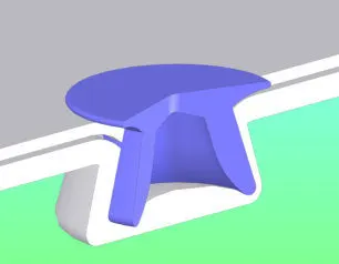
Self-piercing riveting (SPR) is a way of joining sheet materials using a rivet that clinches the sheets as it is pressed into them. Unlike conventional riveting, no hole is required, making it a rapid single-step process.
Unlike welding, self-piercing rivets can be used to join dissimilar metals or non-weldable materials. This is becoming increasingly important in the automotive industry where a mixture of aluminum and steel panels are being used. Self-piercing rivets are, therefore, being used instead of spot welding in some vehicle designs.
SPR is an effective way of joining parts made from any combination of aluminum, steel, plastic or composite.
- Pulling Rivet
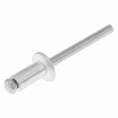
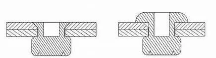
Riveting is carried out in the hole corresponding two the the two parts,and rivet gun is used to expand and deform the outer sleeeve thereby fixing the two parts.
- Folding & Tab Joints(Hemming Joints)
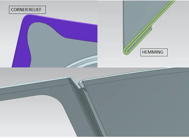
Hemming is a forming operation in which the edges of the sheet are folded or folded over another part in order to achieve a tight fit. Normally hemming operations are used to connect parts together, to improve the appearance of a part and to reinforce part edges.
In car part production, hemming is used in assembly as a secondary operation after deep drawing, trimming and flanging operations to join two sheet metal parts (outer and inner) together. Typical parts for this type of assembly are hoods, doors, trunk lids and fenders.
- Self Clinching
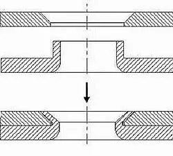
This so called Self riveting is to use the mutual deformation between the sheet metal to complete the mutual fixation.
Although this method is simple, it is often used in place where it is not disassembled.
- Screw Joints & Bolting.
Self Tapping Screws are used to directly tap the thread on a piece of sheetmetal so the fit is very good and can be disassembled.
- Adhesives Bonding
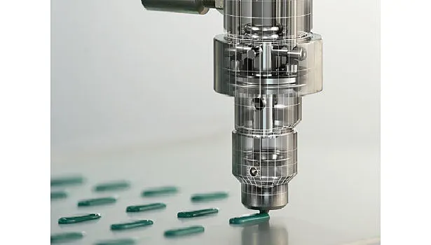
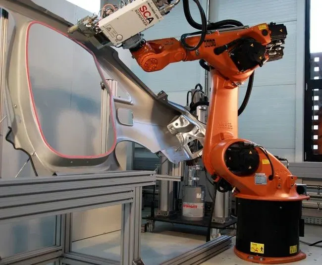
Short-bead technology is used in conjunction with weld bonding, a process that combines spot welding and adhesive bonding.This technology also provides high-strength bonding, reduces body construction cycle time and improves the body’s crash safety performance.Unlike conventional welding, it is suitable for panels made of sheet metal or carbon fiber composites.
2. Metallurgical joints or Welding Joints.
The most common ly used welding methods for automotive applications are resistance spot welding, resistance seam welding, metal inert gas (GMAW) welding, tungsten inert gas (GTAW) welding as also laser beam welding (LBW), friction welding (FW), and plasma arc welding (PAW)
3.What is Resistance Welding & its application in the automotive sector?
- RESISTANCE SPOT WELDING.
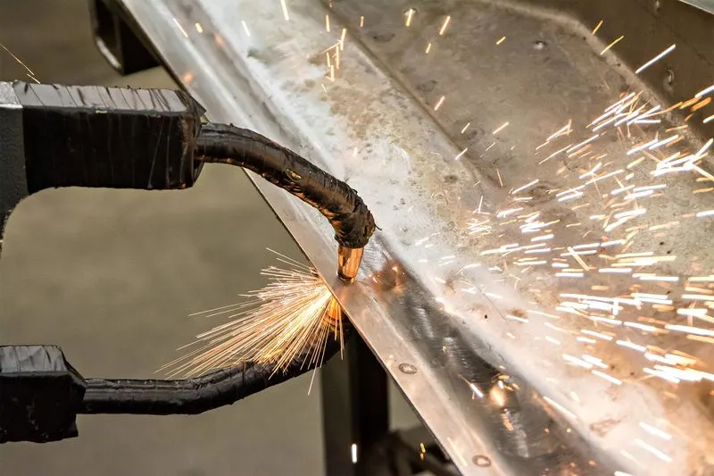
Resistance welding has been widely used in the welding process of underbody, roof, door, side wall and body assembly. The body-in-white structure of a car is its main load-bearing structure.The quality of the whole vehicle plays a decisive role. Resistance spot welding is widely used in the manufacturing and welding of the body-in-white. Statistics show that there are 4000 to 6000 resistance spot welding points on the body of each car. The quality of solder joints is very important in automobile manufacturing, because the quality of solder joints directly determines the quality of the white body, which in turn affects the manufacturing quality of the entire vehicle.
Spot welding is a thermal process in which metals are joined by heat generated by resistance of electric current. In this work pieces(panels)are placed together under high pressure exerted by electrodes. When a large amount of current is passed through the panels , current melts the panelon that specific spot where electrodes are touching the panel and forms weld.
There are various guns to do spot welding but most commonly used guns are X – TYPE and C – TYPE gun. X guns are also known as scissors or pinch gun. These guns are selected on the basis of location of gun mount,tooling access and the geometry of the panel. X-Gun or C-Guns can different shapes of die post as per the requirement.
X TYPE GUN:
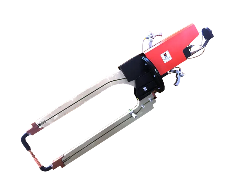
In this gun actuator is parallel to the weld plane and and actuates about a pivot.
X type guns are used where accessibility is constraint.
C TYPE GUN:
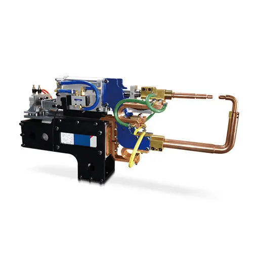
C-type or straight action gun actuates perpendicular to the plane and in line with the weld.
- RESISTANCE SEAM WELDING.
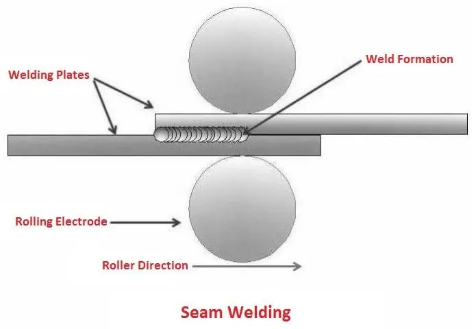
In principle seam welding is similar to spot welding except that it uses disc shaped electrodes. A current impulse is applied through the rollers to the material in contact with them. The heat generated thus rollers to the material in the pressure from the electrodes completes the weld. If the current is put OFF and ON quickly, a continuous fusion zone made up of overlapping nuggets is obtained and the process is known as Stitch Welding Process.
Resistance seam welding is used in automobile fuel tanks, resistance spot welding, seam welding and projection welding are used in the manufacture of automobile shock absorbers, and in the production of automobile rims. To the continuous flash butt welding.
4.What is fusion welding & types of fusion welding with its application in the automotive sector?
- MIG WELDING
Metal Inert Gas (MIG) welding is an arc welding process that uses a continuous solid wire electrode heated and fed into the weld pool from a welding gun. The two base materials are melted together forming a join. The gun feeds a shielding gas alongside the electrode helping protect the weld pool from airborne contaminants.
MIG Welding is mainly for used Chassis & Underbody safety assemblies like Chassis, Rear Axle – RTB, Sub Frames – FCM and Lower Cross Arm – LCA.
- TIG WELDING
TIG welding works on same principle of arc welding. In a TIG welding process, a high intense arc is produced between tungsten electrode and work piece. In this welding mostly work piece is connected to the positive terminal and electrode is connected to negative terminal. This arc produces heat energy which is further used to join metal plate by fusion welding. A shielding gas is also used which protect the weld surface from oxidization.
It is used to weld stainless steel, carbon base alloy, copper base alloy, nickel base alloy etc.It is used to welding dissimilar metals.
It is used to obtain aluminium and magnesium allloy joints in BIW.
- LASER WELDING
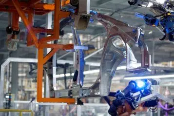
Laser welding is a welding technique used to join multiple pieces of metal through the use of a laser beam. The laser welding system provides a concentrated heat source, allowing for narrow, deep welds and high welding rates. This process is used frequently in high volume welding applications, such as in the Automotive Industry.
Laser welding in the automotive industry has applications that enable manufacturers to weld component engine parts, transmission parts, alternators, solenoids, fuel injectors, fuel filters, air and conditioning equipment as well as many other applications. Laser welding is a great tool due to its ability to weld pre-machined components with restricted heat and minimal distortion.
- FRICTION WELDING
The induced mechanical motion of friction welding generates heat, causing the materials to be joined to soften and become viscous. While in the softened state, the mechanical motion of the process mixes the materials to create a bond.
Friction welding has been used in the commercial automotive and lightweight automotive industry for decades and is a proven-effective technique for joining banjo/trailer axle housings, pistons, driveshafts, turbochargers, airbag inflators, stabilizer bars, engine valves, transmission gears, bumper shocks, suspension components, water pumps and more.
- PLASMA ARC WELDING
Plasma arc welding (PAW) is an arc welding process very similar to TIG welding as the arc is formed between a pointed tungsten electrode and the workpiece. However, by positioning the electrode within the body of the torch, the plasma arc can be separated from the shielding gas envelope. Plasma is then forced through a fine-bore copper nozzle which constricts the arc.
5.What is the 3-2-1 principle?
In BIW FIXTURE design the panels are always fixed with the help of 3-2-1 .because it always minimizes the usage of unwanted components to hold the panels with the help of 3-2-1 principle we can arrest the six degrees of freedom which means six degrees of rotational and six degrees of translational axes .
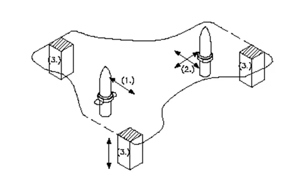
3 locators position a part in a primary plane or direction .
For the primary locating datum, the area of the triangle formed by the three locating points should be as large as possible.
2 locators then position the part in a secondary direction (e.g., in/out)
For the secondary locating datum, the distance between the two locating points is as large as possible, and the line segment connecting the two locating points should be parallel to the primary locating datum if possible.
1 locator for the tertiary direction
For some product designs, manufacturers replace the three locators for the secondary and tertiary directions using two round pins, one fitting a circular hole and the other a slot. The pin locates the part in two directions (e.g., in/out and fore/aft). The slot then becomes the other locator for the secondary direction (e.g., in/out).
This approach satisfies the six degrees of freedom constraint of the part in jig / fixture designing.
LOCATING SELECTION CRITERIA FOR EXAMPLE
Locating pins are the preferred choice for primary location.
The best and most cost effective method of part location is referred to as the 3-2-1 method.
3.) Minimum (3) locator blocks to establish part plane.
2.) (1) Round locating pin in a round hole that defines location in four directions (4 way perpendicular to the plane previously established).
1.) (1) Round locating pin in a slot that defines two of the directions of the other pin (2 way).
6.Define Body coordinate system?
A coordinate system is a system that uses one or more numbers or coordinates, to uniquely determine the position of the points or other geometric elements on a manifold such as Space.
Body Coordinate system in BIW is also called Carline.
All vehicle product drawings are identified numerically relative to three vehicle planes Description shown below.
1. ( X ) It is in length of BIW – 0 X is Near Front Bumper
2, ( Y ) It is in width of BIW – 0 Y - is Body Center Line
3. ( Z ) It is in Height of BIW - 0 Z is about Center of Wheel. Below image represents typical Body Cooridinate system.
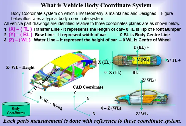
Car lines are the (Grid lines) shown on the fixture , which virtually represent the same location in the BIW. All the car line on fixture display the coordinate at corner for reference .
With these lines one can easily relate the ,location in BIW.
We should try that the co-ordinates of locating and clamping points should not be in three decimal (e.g. X=100.124, Y=245.127, Z=450.458).
They should be in the whole nos. or max upto 1 decimal . Once these co-ordinates are maintained automatically the BIW base structure is maintained.
7. Elaborate Body plane system & its essentials.
Body Planes are reference planes in an automotive car.GD&T for all the car parts are defined using this planes.
These are three mutually perpendicular imaginary planes considered to be present at the driver position or sometimes at engine location or at the front end of the car.
By using these cooridinates while designing we can reduce the assembly errors.