Week 3:- BiW Fixture Design Methodologies Challenges
What is Design Methodology?
Design methodology is nothing but the steps followed during the concept design stages of the fixture design.
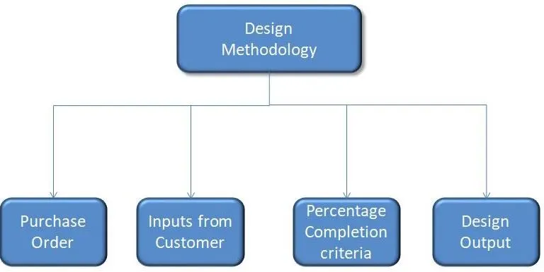
What are the inputs required from the customer to start designing a Fixture?
- Functional Requirements :In this customer will define for what purpose fixture will be used.
Example :Welding Fixture (Spot Welding Fixture or Seam Welding Fixture).
Hemming Fixture
Checking Fixture
Storage Racks - Preffered Standards:
- Standards like ABB, NAAMS,DESTACO,ZYTRAN,TUENKERS ETC.
- Standard Parts like Risers, L-Blocks, Retainers, Pins which are already design by customer& can be used while designing there by saving the time & manufacturing Costs.
- Components to be used like Clamps, Cylinders , Slides , Switches, Sensors.
- Weld Guns, Tip Dressers, Tool Changer.
3.Car Products.:These include
- GD&T
- Part List.
- Cad Files of Car Part.
- Clamp Plan and PLP points.
- Product assembly Process Sheet.
4.Layout: Its Layout of the entire Car Manufacturing Assembly line to understand the process, flow of work and Space constraint we have to consider while designing.
5.Ergo Data : Ergo Data is required while we have manual operated fixtures. Each customer will have different standards which has to be incorporated while designing and also while giving the final output data.
6.Weld Study : Study of particular Gun which will be used for welding.Also study what kind of spot welding to do & no of welding to do on a particular assembly.
7.Standard Detailing Template : Customer will provide with the standard template to be used for the 2D manufacturing Drawings.
What is the input we get from "Car Products"?
- GD&T
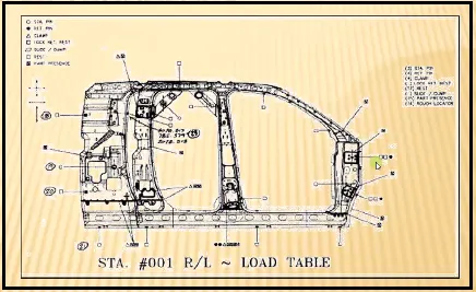
GD&T Provides information of Locating pins, Rest ,Clamp ,Dumps & Slide information of each station And also Sequence of opening of clamps,dumps & Slide stroke information.
2. PartList :
It is a list containing various information of the Car Panels that are welded such as part number, revision number and thickness of the parts to be welded. Thickness of the car panel is the important parameter to consider since it decides type of welding gun to be used and type of the welding to be done.
3. Clamp Plan
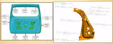
It provides the information of the various points such as pin support points, Clamp points and Rest Points on the Car Panel to be welded on the fixture.
4. Product Assembly Process sheet.
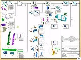
This is the sheet which provides information about how part going to move from one assembly to other assembly to form the final required product.
5.Layout
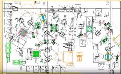
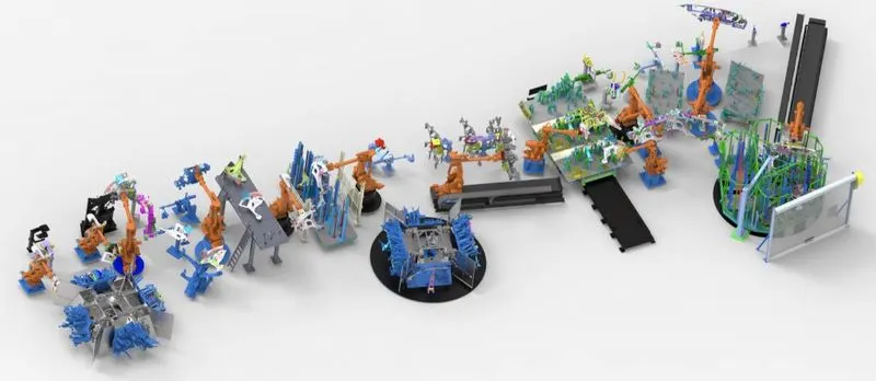
Layout sheet gives information about how fixtures are placed and how robots are going to work on it showing the reachability of Robots.This sheet provides entire plan view of the various stations and also space constraint for desgining the fixture.
What is the Clamp Plan?
Clamp Plan is the diagram which shows different Pin points, Clamp points and Rest Points on the Car Panel. These are defined using the 3 coordinate points measured from the Carline.
While designing BIW fixture we have to design clamping and pin location at the point indicated on the clamp plan. If there is need for any changes required in clamp plan we have to take approval from the customer.
What is the purpose of a Layout?
Purpose of the layout sheet is to let the fixture designer know the how fixture and robot interact with each other . It is also usefull to understand the process flow for manufacturing the final product. Its also lets designer know the space constrain while designing the fixture.
What is Ergo Data?
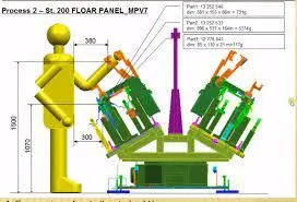
Ergonomics is the process of designing or arranging workplaces, products and systems so that they fit the people who use them.While designing the fixture we have to consider various points so that the operator working with fixture works at good effiency. Ergo Data provides information of the loading Height & Working Safety Zone of the Operator.
What do you understand by Weld Study?
Weld Study includes
1.Weld gun Details
2. Weld Matrix & Weld Points.There are two types of welding points to consider a. Geo Spot Welding points b. Respot Welding Points .
What are the criteria for percentage completion in the designing stage? Explain it in detail
Percentage completion criteria is followed in designing stages and dispatch stages of weld fixtures.
0-25% - Input and Concept Design . In this stage input from the customer is studied and Concept is prepared after studying inputs.Concept is sent for customer approval.
25-40% - Concept Approval and Simulation Check
Once Concept is approved by the customer 3D modelling of the fixture is completed. 3D finish is done by adding holes and fasterners etc. Simultaneously simulation check of the 3D modelling is done to verify whether there is any fouling with the Robot welding Gun and Open position of clamp arms is checked. Robot simulation is also used for Gun Selection, Tool Validation, Layout finalization with minimum space utilization, Cell Design Etc.
40-85%- Design Freezing and Detailing.
In this stage 3D design is freezed .After sending to customer and implementing the feedback from the customer next stage is to create detailing drawing for each Units and its parts. The Drawings are done as per the Customer standards.
85-100% - Check and Final Dispatch.
Once Drawings are done. Final Quality check is done and Final Dispatch is done along with the proper documentation.
Brief about "Output" in design?
The output is the 3D model and 2D drawings of the Tools.
Unitized Tools: ( Multiple unit on a common base) require two types of drawing sheets
- KeySheet : Index of all units and their placement on the Tool Base.
- Layout sheet - a detailed drawing of individual units t include all of their components.
Non Unitized Tools: Tool that can be standalone and can be detailed completly on layout sheet. Example Stands, Gun Changers,etc.
Output should consist of following points.
- Approved standard components to be used whenever possible
- Design must be simple and economical as possible.
- Design must comply with all current safety and ergonomic requirment.
- Design must provide for controlled and damage free handling of product.
- Adequate error proofing provision must be incorporated into each design by providing Proximity switches, Rough Locators Etc.
- Weight of moving part has to be kept minimum while maintaining maximum strength.
- Frames and structures to be simple and sturdy.
- Design accessibility for routine maintaince and service.
- Motion control must be considered on any moving equipment.
- Designer is responsible to validate Clamps and all weld Guns.
What do you understand by structuring a design tree? How does it reduce errors during the design process?
- Structuring design tree is a process where all the assemblies and parts are named in specific standards.There will be different standards to be followed which will be customer specific.
- It is an important process which helps us to indentify a specific part or assembly as to which project, tool or unit it belongs to.
- This helps us to avoid errors during design study, manufacturing, assembly inspection etc.
- If the parts and assemblies not named properly or the design tree is not structured properly it will create confusion and major probability of error.
- It will help us identify quantity of items of same type or of different types that are being used in assembly.
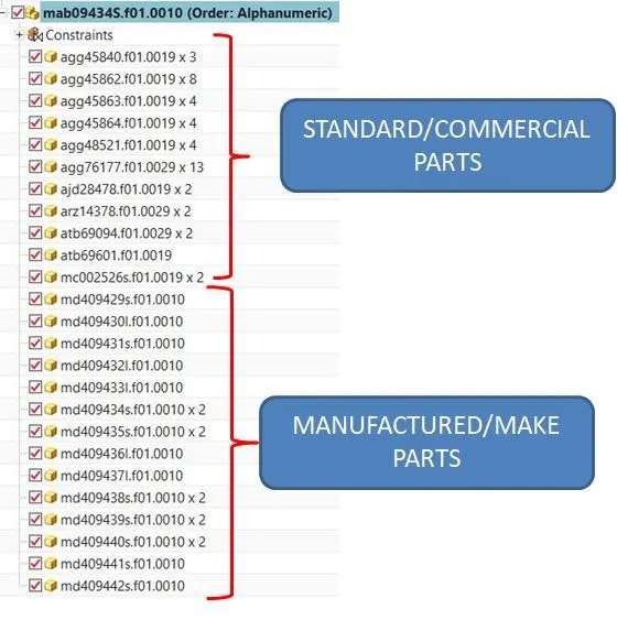
In the tool standard practise is to name base unit as the first unit. Then comes Pin Units, Rest Units, Clamp Units, Dump units Etc.ill
What are Units? Mention 5 types of units.
Units are the subassembly of the unitised tool. Different units together form the complete Tool. Each unit in the tool will have specific function to perform.
There broad two category of tool
Simple Units
- Rest Unit
- Fixed Pin Unit.
- Retract Pin Unit.
- Rough Locator Unit.
- Sensor Unit
- Base Unit
- Clamp unit
Complex Unit
- Slide Unit
- Dump Unit
Describe Fixed Pin Unit and Their purpose ?
Fixed Pin Unit is designed to locate the car panel using pins.
Typically, the locating pins are used to lock a body part in a position sufficiently accurate to execute a welding process.
Usually two locating pins are enough to properly locate the body part on one plane. One of the pins is round, and another one is diamond shaped. This configuration will allow easier loading of body part.
What are the different parts of the fixed pin unit?
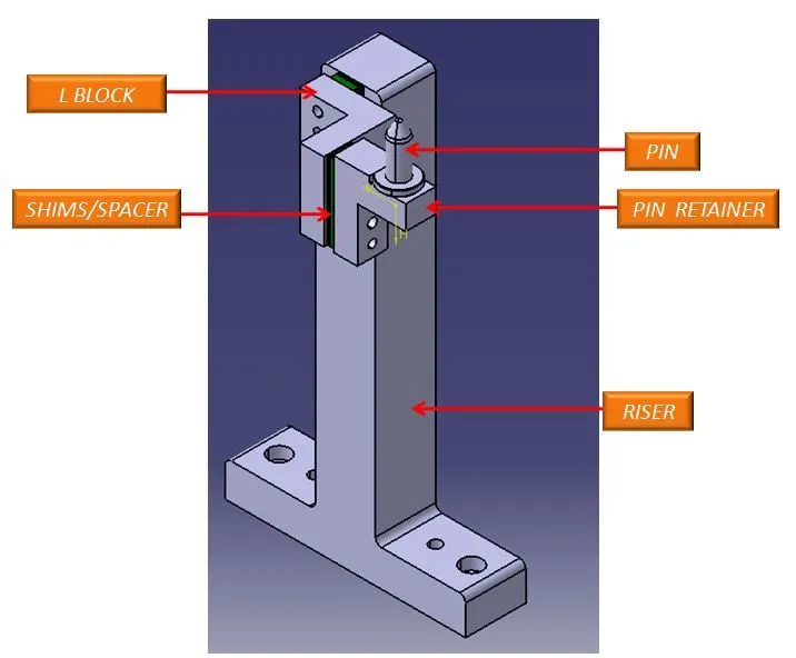
1.Locating Pin :- Pins are used to locking the rotational movement of the panel. Generally there two types of Pins, one is Round Pin and another one is a Diamond pin. We use two and three-directional shimming for pins as per the angle of the pin w.r.t. the carline. In some cases, we use a collared pin, when the pin is supposed to support the panel as well. For this kind of pin, we provide 3 way shimming irrespective of pin angle to the carline.
2.Pin Retainer : Pin Retainer holds the pin and rotational motion of the pins. Pin Retainers can be standard or manufactured one.
3.Shims :- Shim is a set of thin plates (2 mm, 1mm, 0.5 mm, 0.25mm) that are used to adjust the gap or used for a better fit. Shimming can be of thickness 5mm, 8mm, or 10mm. in case no proper fitting between mylar and Panel due to manufacturing errors then this error can be removed using shims. Shims are placed in the carline position so that gap can be adjusted in the required direction like X, Y, or Z.
There are three types of shimming. These are one-way, two-way, and three-way shimming.
Number of shimming depends upon the NC cut angle and PIN angle with the car line.
If NC cut is less than 15 deg then mylar will have one-way shimming.
If NC cut is more than 15 deg in one direction then mylar will have a 2-way direction shimming
If NC has more than 15 deg angle in two directions then mylar will have 3-way directional shimming.
But in the case of pins, this case is a bit different. If the pin is on the angle with respect to the carline and that angle is more is not more than 15 deg then the pin will have 2-way directional shimming, if Pin’s angle is more than 15 deg in any direction then 3 shimming will be used.
4. L Block :- A plate shaped as L is called an L block. This part is used as a connection between mylar and Blade. Generally, L blocks are used to provide shimming. It is not necessary that L blocks are only used for shimming, its uses changes as per the requirements, At some places, it is used just to connect one part to another. Similar to the L block one more block is used which is in the shape of T. So this block is called a T Block.
4. Risers :- The part which is mounted on the base plate and holds a clamp or pin cylinder on it, is called Riser. Riser can be Standard Part or manufactured part, it varies from project to project. A riser can be a Single part or welded part. Standard risers also have various shapes and sizes.
What is the purpose of making a Rest unit & describe its parts?
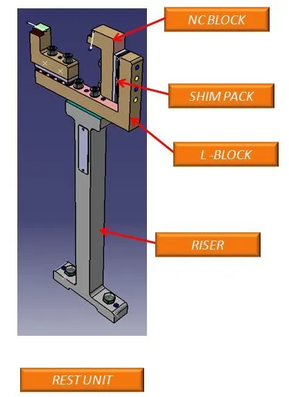
The rest units are designed to rest or support car panel using NC blocks.It has fewer parts hence it is easier to design. Its purpose is to provide resting of car panel. It can be combined with Clamping unit to provide clamping as well as resting for car panel. It can be combined locating unit of combine locate and rest the car panel.
Rest Unit usually consist of NC Block, Shims, Blade and Riser.
NC blocks :- NC blocks or Mylars are a one of kind block that holds or clamps the panel.Mylars are mounted on any block or plate with Shimming, So that height of mylar can be adjusted accordingly at the assembly level.Shimming can be 1 directional, 2 directional, or 3 directional as per the NC cut.
Shims:- Shims are thin set of Plates that are used for adjustment.
Blade:- The plate which connects Riser to the Clamp cylinder is named Blade. This plate plays an important role in building the unit. The plate can be of any shape. But we need to keep in mind that the plate should be as compact as possible.
Riser :- It is the part which is mounted on Base Plate. It is used to mount blade on it. Riser can be standard part or make part.
What are the basic fundamentals to design a Sensor unit?
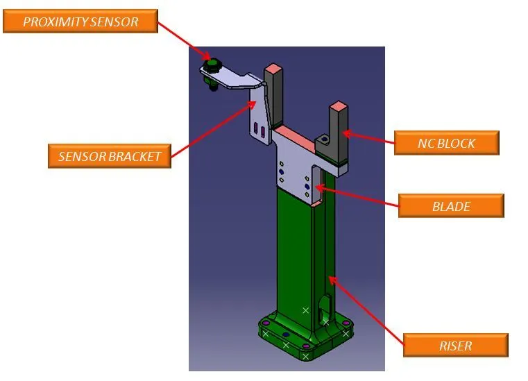
It is unit designed to sense the car panel by using Electrical sensors.
Signals from the sensor is fed to PLC and so the next process will be executed from this signal.
Fundamentals of Sensor Unit Design :-
- Every single loose panel which is being welded by the tool should be sensed.
- Each panel should be sensed by 1 or 2 sensors depending upon size of the panel.4
- Every Sensor should be mounted in a 3 Direction adjustable way in general.
Major sensor manufacturer are IFM, Pepperl-Fuchs,SICK,OMRON etc.
Types of sensor generally used are:
- Proximity sensors
- Laser sensors
- Photoelectric sensors
What is a Rough locator unit & what are the basic fundamentals to consider while designing it?
Rough Locator is the part designed to guide the operator,to locate the Car panel onto the pins accordingly. It works as a Poka-yoke mechanism in a process that helps an equipment operator avoid miakes and defects by preventing, correcting, or drawing attention to human errors as they occur. Rough Locator can be standard part or make part.
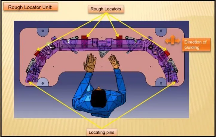
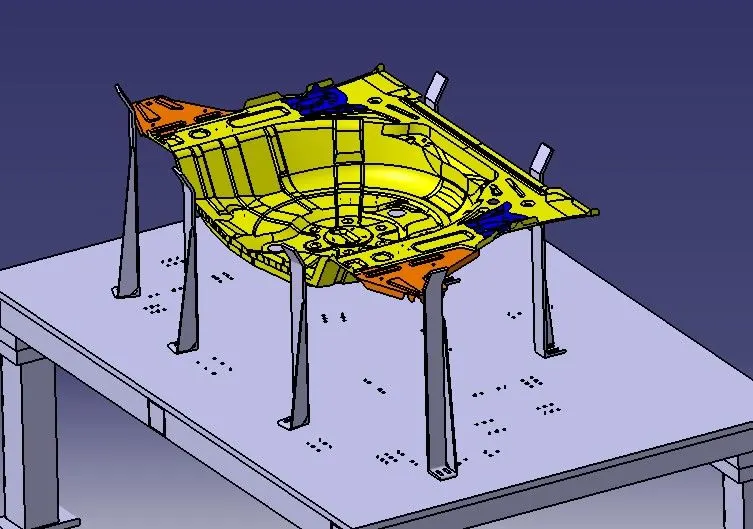
Fundamentals of Rough Locator Design:
- Rough Locator should be placed at the edges of the car panel,which it has to guide.
- Rough Locator has to be placed in the same angle of the car part edge with a minimum distance of 2- 5mm from the edge of the car part.
- Rough Locator should guide the panel in the Pin arrresting direction.
- Rough Locators should start guiding the panel before 10 to 15mm to the start of the pin engagement.
- Rough Locator should be designed with entry angle for car part entry.
- Rough locators should be designed with two slots to mount for easy adjustments.
- The slots should be in the direction of car part guiding.
What is a Base unit and describe it's parts?
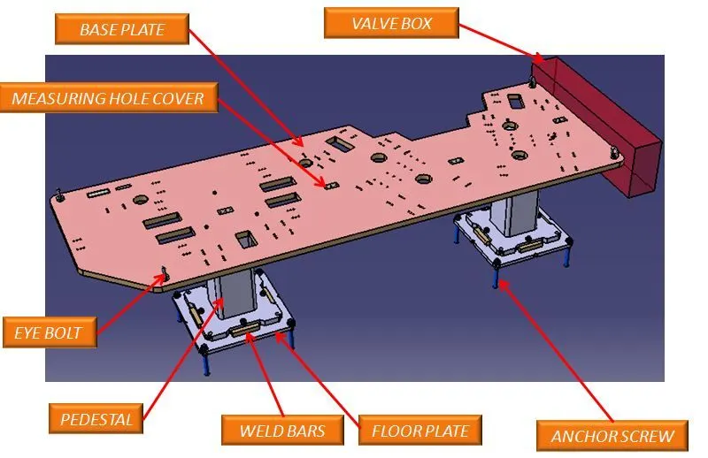
Base unit is the unit designed to mount all other units(Clamp unit ,Pin Unit, Rest Unit etc) of the tool.Also other parts neccesary for tools such as pnuematic valve box, trunking cable path are all mounted on the Base unit.
Parts invovlved in the base plate are as below
Base Plate :- It is a plate where all the units are mounted.Base Plate is machined in such a way to maintain flatness & Parellism of the plate. Plate thickness should be adequate to sustain loads from all the units .
Valve Box & Trunking Channel :-Valve box consists of set of solenoid valves which is used to supply compressed air to different cylinders used in Units. The Valve box consists of one input connection and one output connection.All the soleniod valves are placed inside the valve box. Trunking Channel basically acts as protection cover for all the pnuematic tubing used in the Cylinders.
Eye Bolts :- Eye Bolts are used to lift the fixture and move the fixture using ropes and cables.
Measuring Hole Cover:- Measuring holes or Tooling are drilled in the base plate and all the other holes are drilled on the base plate using this hole.So measuring holes are basically reference holes. Measuring hole cover used to cover these hole.These measuring holes are also of usefull during QC inspection of the fixture. CMM machine uses these holes to check the fixture.
Pedestal:- Pedestal is a support on which base plate or Base frame is mounted.
Floor Plate :- Floor Plate is used to join the fixture and floor together.
What is a Dump Unit and what are its functions?
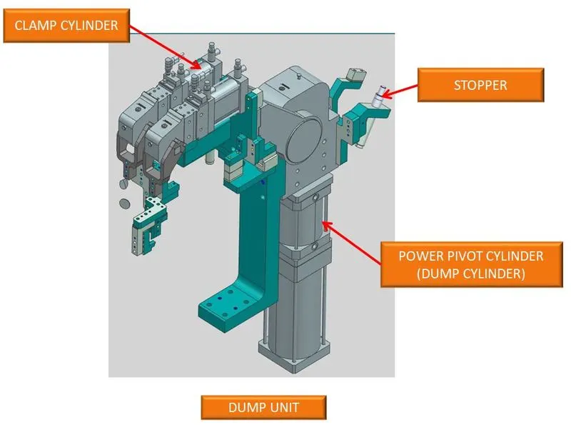
Dump Units are used to dump the car part onto the fixture & dump the fixture into working poisition when different varients are used.Dump Units are complex to design due to space constrains .
Different parts used in the dump unit:
Power Pivot Cylinder(Dump Cylinder) ,Bracket, Clamp Cylinder, Retractable cylinder, NC blocks ,Location pins & proximity switches, Stoppers ,Manual lock pins.
Also Dump units are used when there are two varients of carparts gets welded on the same BIW fixture.When X Carpart comes into station , the clamp or retractable pin units are in dumped out position and when Y car part comes it is dumped in to the position.
What is a Slide unit? Mention where Slide units are commonly used.
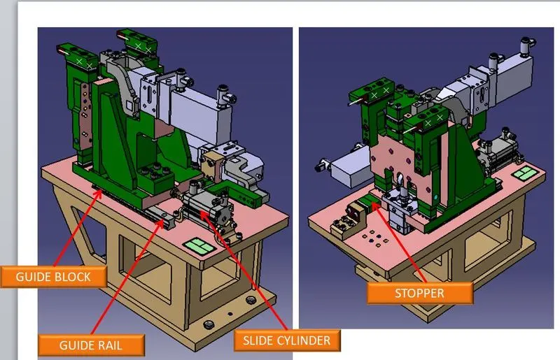
Slide units are positioning units which are used to position car part, units , weld gun or Robots into position for further operations.
The LM guide rails are usually used to position the slide units.
Slide units usually consists of LM guides , Slide Linear Cylinder , Front and Rear Stoppers,Front and Rear shock absorbers, Two Proximity switches for sensing two end positions,Protection covers for Rails.
Slide units have to be locked/clamped in the working position.