Week 2:- BiW Fixture Basics Challenge
1 )
Project Execution Process :
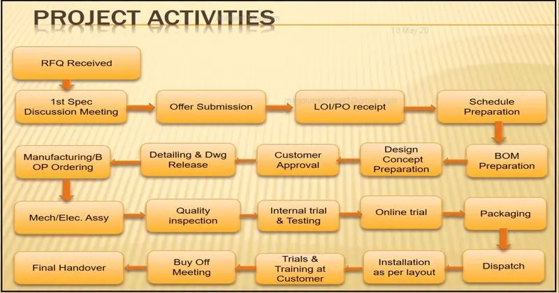
The project execution process is the process of developing the model of fixtures from the initial stage to the final stage of processing it into the desired format through the steps of generating the fixture model in the following steps.
First the RFQ is obtained by the dsigner and the following steps are carried out in the process.
The first step discussion meeting is donw to generate the offer submission. Then the PO receipt is done and the preparation is scheduled. Then the BOM (Bill of Materials) is prepared for the customer support and then given out for the customer support. Then the detailing and the DWG release process is done. Then the manufacturing and the OP ordering are done. Then the mechanical and the electrical assemblies are bought fixed to the sections. The electronic components include Reed switches and sensors such as ultrasonic to measure the distance and also the thickness of the material.
Then the first quality inspection is done along with the internal testing.
Thereafter comes the simulation team comes into picture, they have to provide validation for the model that has been proposed. If the validation is approved then the next step is carried out orelse the model is again sent back t the conceptual 3D design team. The next step after simulation validation is the Quality check (QC). If the ,model passes the QC it will be sent to the Customer review team for updates. If there is any feedback given by this team to improve then the model will be send back again to the 3D concept team for updation or the model will be passed to the 2D detailing team. Where the 2D detailing is the drafting process of the 3D model and the model is being given to te quality check of the 2D drawing and will be given to the manufacturer for any drawing doubts because, if any then the process will consume a lot of money and time waste. Once all the processes are verified then the model is send to the manufacturer for manufacturing.
2)
Types of Joining process :
Joining Process :
Joining process is the process of joining two or more metals togather to form a different shape or desired shape. The joining of metal components is done to make the parts stronger anf also to fit the geometric spaces of the adjoining parts. There are different types of joining processes that are used in the manufacturing industried according to the aesthetics of the model, cost availability, Time constraints and strength requirements.There are many methods to join one part of a metal to another part of the metal. The fastening options are selected accordingly to suit the best for the affordability and the purpose. Some of the most important joining methods are
- Mechanical Fasteners
- Self piercing rivets
- Hemming process
- Adhesive bonding
Mechanical Fastners :
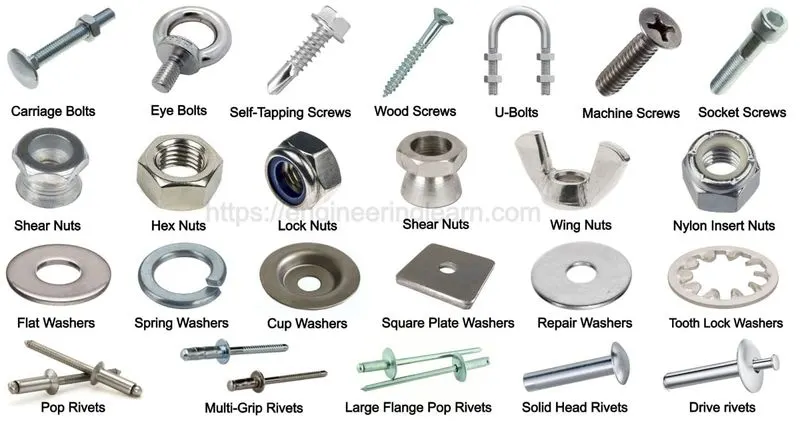
The mechanical fasteners are the common nuts and bolts. We normally prefer to use fasteners in the class B surface where welding is not a viable option. For ex. aluminium has lesser melting point has poor compatability with welding.
Self Piercing Rivets :
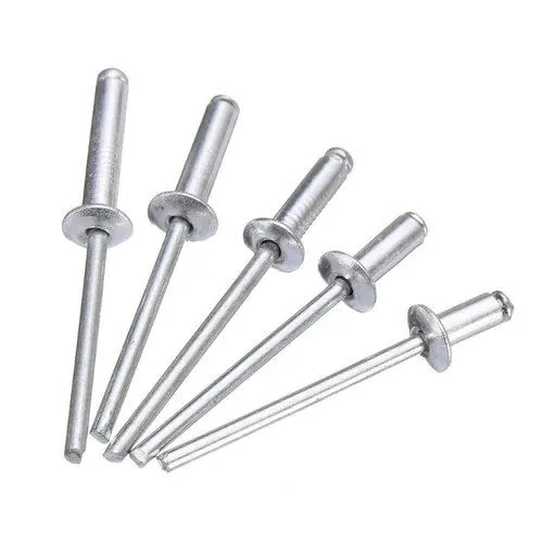
Rivets are generally the part that locks itself with the model with just applying less pressure. The advantage of the rivet is that it can hold the parts togather and doesnt gets lose because of the vibrations caused by the adjoining parts.
Hemming process :
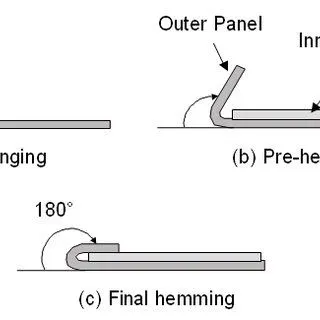
The hemming i sthe process of bending one metal part over the other part to provide a support and thereby holding the part inside the outer panel without the help of fasteners, rivets or welding process. The commmon place where hemming is done is on the hood inner and the outer panel where the outer panel is turned around the surface of the inner panel in such fashion as the form like a cover over the inner panel. This process is often a costlier process where in comparison with the other methods that can be done. The reason why it is done instead of other methods is that the joining process wouldnt affect the styling surface which inturn gives the cusomer a pleasing look from outside or his viewing point.
3)
Resistance Welding :
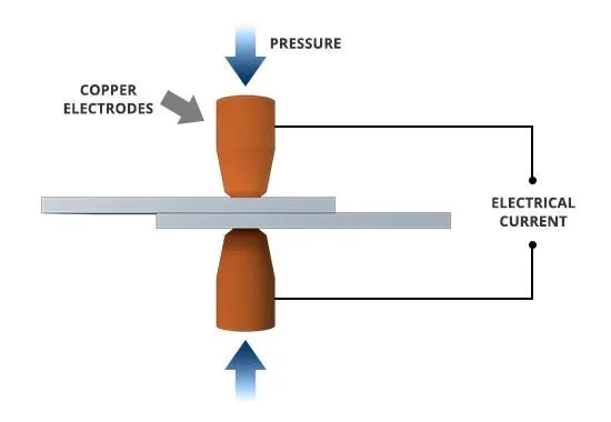
The resistance welding which is othervise known as the spot welding is the most commmonly used welding technique that is almost used allover the world for joining process in the manufacturing process. In this method, the metals that are to be spot welded are brought togather and welding held tight with the electrodes. Then these electrodes exert pressure on the metals against each other and uses current to produce heat and join the adjoining metals. The current passing through the metals generate heat and this heat makes the component to stick togather and it forms like a nugget shape weld. After the current is passed through the metals the electrodes are still applying pressure to certain yime to make sure the weld is properly done and it also provides extra strength for the weld. This time taken to make the metals stick togather is caled the WHOLE TIME.
The electrodes used in the process are commonly made of copper-chromium alloy and zirconium.
Their use in Automotive Sector
They are commonly used in manufacturing processes in the automotive sectors of the chassis. For example, the chassis of a specific motorcycle company uses spot welding to weld the frame to the engine mounts and also all the extensions such as swingarm mounts, suspension mounts and harness clamps. They widely use spot welding because of the cost affordability and its lesses time consumption for each weld to make.
Advantages :
- It has short weld time and also has high welding strength and speed (approx 2 seconds per weld)
- Adaptable to robotic techniques
- This is high in strength and it is very durable
Resistance Projection Welding :
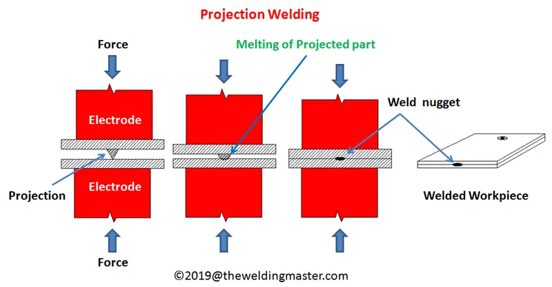
The projection welding is the same as the spot welding. Whereas the only difference with the projection welding and the spot welding is that the shape of the electrode. The shape of the projection electrode is not standard because the shape entirely depends upon the metal that needs to be welded upon. The tip of the electrode will have embosses that are specially made to be projected exactly along the shape of the metal to be welded upon. The disadvantage of the resistance Projection welding is that the cost of the welding is comparetively higher.
Resistance seam welding :
The resistace seam welding is the type of welding where the electrodes will be in the shape of cylinder and the spots will be made in series to make it look like a continuous welds. The welds are connected in this fashion and the local strength of the material will also be increased. The weld will be done through out the seam in series. They are mostly used in Ventilators and Heat exchangers.
4)
Fusion Welding
Fusion Welding is a process of melting two or more metals to join them by heating into melting point of the material. There are several types of fusion welding such as Gas shielded metal arc or MIG welding, TIG welding, Plasma arc welding, Submerged arc welding, Flux core arc welding.
Manual Arc Welding :
The arc welding is the process of using consumable electrodes to weld the components and form the desired components.
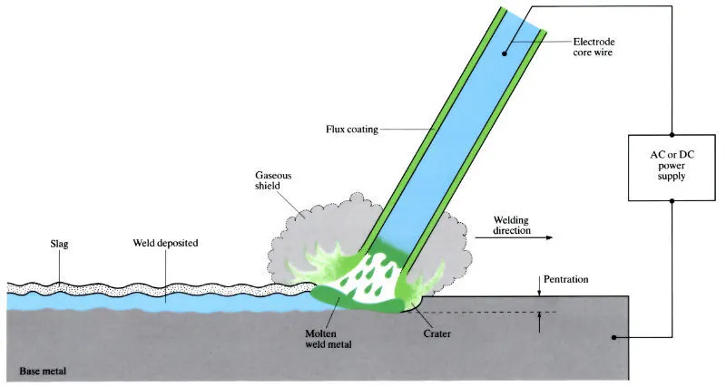
The most commonly used fusion welding methods are,
Some of the important joining processes are mentioned below,
Gas Shielded arc welding :
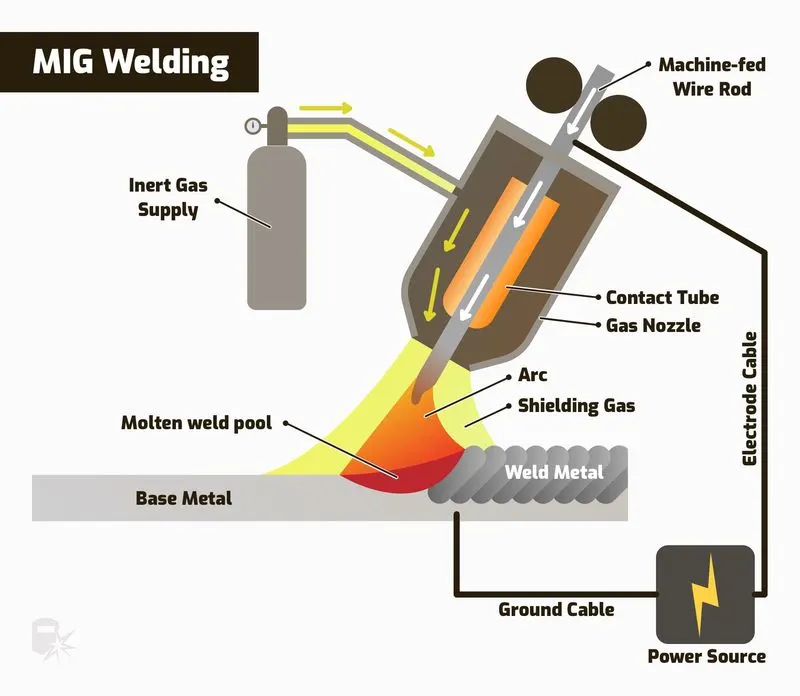
It is also known as Gas Metal Arc Welding (GMAW). MIG and MAG welding are the most common arc welding processes, in which an electric arc forms between a consumable wire electrode and the workpiece leading them to melt and join. Both use a shielding gas to protect the weld from airborne contaminants, or oxidation in the case of MIG welding.
The MIG is abbrevated as Metal Inert Gas welding.
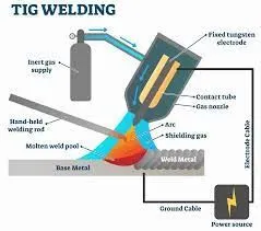
TIG Welding :
It is also known as Tungsten Inert Gas welding is the process of welding where we use non consumable electrodes to melt two or more metals to join a weld.
5)
3-2-1 Process
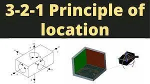
The 3-2-1 process is the process of arresting all the degrees of freedom of the model while it is fixed on the dock stand. The 3-2-1 process id carried out for easy and accurate processing of the model with spot welding, piercing, lancing or any other process that needs a stationary position of model.
Working :
There are 12 degrees of freedom for any component that gets fixed on the dock stand. They are
6 translational motion along x, y, z, -x, -y and -z axis.
6 rotational motion along x, y and z axis. ( Clockwise and Counter clockwise )
In the first step, the workpiece is placed on the stand to the 3 parts that clamps the workpeice and arrests 2 translational motion and 4 rotational motions.
In the next step, a pin is inserted which is in the shape of circle arrests 4 rotational motions and 2 translational motion
In the last step, a pin in the shape of oval get in contact with the workpeice stops the last two translational motion.

6)
Body Co-ordinate system :
The body coordinate system is the system that defines the coordinatets of a car along the x, y and z axes. The earth coordinate system along with the vehicle coordinate system is guven below,
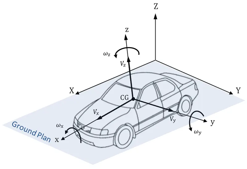
They are generally used for designing and orienting the parts of the vehicle.
The x axis is the longitudinal axis where the center line of longitudinal axis is called the FOL (Front O Line)
The y axis is the transverse axis where the center line of this axis is called the COL (Center O Line)
The z axis the vertical axis where the center line of this axis called th BOL (Bottom O Line )
7)
Body planes
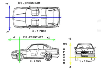
The body planes gives us the knowledge about the orientation of the car in a 3D space.
They are widely used in the automotive design sector for locating the components in various occasions.
For ex. The location of the back door hinge is given as 205,54,33 by the designer to the first customer i.e. the CFD team. The CFD guy will be opening the model in is respective software and serach for the hinge by placing the body planes in accordance to the datum cordinate system and easily identify the part's location.
After identifing the location of the part he will simply carry out the operation that he has to do in the model and give a input back to designer about the working compatibility of the hinge axis in the car.
And the important thing for a designer is that the designer must always follow the Body planes and Body Coordinate system while designing the vehicle's parts, so the next step will be carried out easily or even if there is any change to be made in the model, it easily can be carried out.
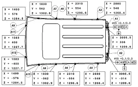
The co ordinate system of the roof various parts the roof is dimensioned for easy locating of the parts and they can used for identifing other parts located near to it.