Week 2:- BiW Fixture Basics Challenge
- what is the process of project education activity?
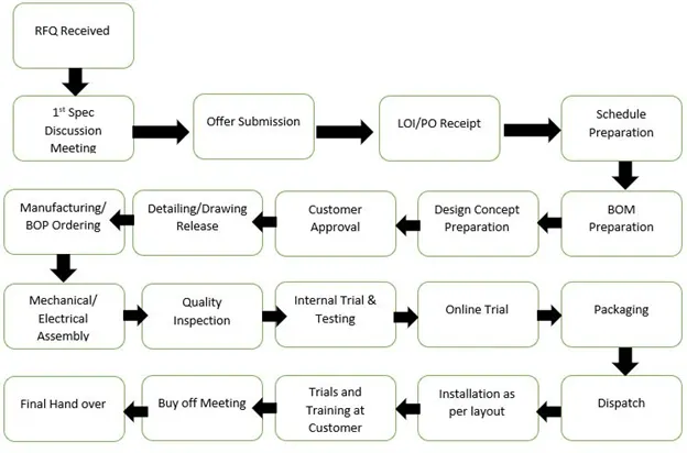
- The process of project education activity involves series of steps as discussed below.
- RFQ received: - Request for Quotation is the first and foremost step involved in project execution. In this type, the customer quotes his requirements, specification, technical offer, commercial offers, expected timeline of the project and other detailing in form of documents.
- 1st Spec discussion meeting: - After receiving the RFQ the discussion meeting will be carried out on technical offer, commercial offer, project execution timeline required to complete the project and will be finalized. In this meeting the time required all the steps from our rough drawing to final manufacturing are considered and cost and time minimization will be given more priority in this discussion.
- Offer submission: - The finalized results of the 1st spec meeting will be documented and submitted to the customer for review and feedback.
- LOI/PO: - The offer letters received to the customer will be reviewed in all aspects and best suited will be approved and purchase order of the project will be sent.
- Schedule preparation: - After receiving the PO the project schedule preparation will be done to meet the deadlines and to complete the project. All the steps in the project are considered like PO receipt, 1st spec design meeting, design data analysis, 3D design preparation and simulation etc. the time required to finish the individual activity is calculated. And then total time will be calculated to check whether the project can be finished in specified time or not. If it seems to be not possible alternative plans are also to be prepared. These alternative plans come into action in project completion whenever there are deviations.
- BOM preparation: - Bill of material is prepared for the project by considering each and every step and it will be listed out.
- Design concept preparation: - Based on the customer requirements and specifications the design of the project and details of the project are prepared in this step and sent for the approval of the customer.
- Customer approval: - In this step customer reviews the design and check whether the design fulfills the requirements or not according to the technical offer. If everything is good then customer gives the approval otherwise suggestions and corrections will be sent on which we have to work on and again we have to send the approval. This goes until we get the final approval from the customer.
- Detailing & drawing release: - After the customer approval. Detailed drawings and designs will be released of all the parts required. Like dimensions, quantity, specifications etc.
- Manufacturing/Electrical assembly: - In this step the manufacturing process begins. Before that the required parts like motors, cylinders, sensors, gripper, etc. for manufacturing are ordered as per the design specifications.
- Mechanical/Electrical assembly: - In this step all the parts received from BOP ordering will be analyzed for quality check and then the mechanical and Electrical assembly of the parts will be done.
- Quality inspection.: - After the assembly, the assembled part will be done with quality checks. In this all the dimensions, positional accuracy, coordinates are checked by using CMM machine. Once all the quality checks are passed then only it will be sent to next step otherwise it will be sent back for obtaining good assembly.
- Internal trial & testing: - In this step, internal trials are done on the fixture to evaluate its operational feasibility. For this day from various simulations and munual trails for the testing of the fixtures.
- Online trial: - It is done in an automated mode by using electrical connections. The process sequence is checked as per defined way in design. This is done in front of customer to take their approval as well.
- Packaging: - The assemblies are packed in proper manner in such a way that no damage occurs during transportation. Otherwise a small damage will lead to distortion of the geometry of the fixture and also the functionality of the fixture. Hence the proper packaging is very important.
- Dispatching: - Once the packaging is done, the picture will be dispatched to the customer address.
- Installation as per layout: - Layout is the space defined for the parts like fixture, robots etc. The layout is designed by considering the functionality, application process, sequence etc. Hence installation is to be done as per the layout.
- Trials & Training at customer: - Production trials are performed at customers end after the proper installation. In technical offer, we have specified the quality benchmark, the capability of the fixture for production, etc. The trials are done to check and show the capability of the fixture to the customer. After the trials the training is given to the operator, staff and engineer for the process sequence, how the fixture works loading and unloading of the part, etc.
- Buy off meeting: - In this meeting the we all allow the customer to ask their doubts and also, we provide additional information related to project. By the end of the meeting all the details and doubts will be cleared to satisfy the customer and help to proceed further with product.
- Final hand over: - In this step product is finally handed over to the customer.
- What are the types of joining processes?
- Joining processes involves joining of two metal parts, either temporarily or permanently with or without the application of heat or pressure.
- Joining can be done in two types
- Mechanical joining
- Metallurgical joining
- Mechanical joining
1. Mechanical joining
- It is a process of joining using mechanical methods which involves screw, nuts, rivets and bolts etc. The threaded holes employed for mechanical joining are vulnerable to fractures. In ductile materials, the fractures can come from fatigue, while in brittle materials, the fractures can simply result from mechanical overloading. Thus, mechanical joints must be designed with fatigue failure and brittle fracture in mind. In mechanical joint there is prone galvanic corrosion. Hence while designing mechanical joints it is to be taken into consideration.
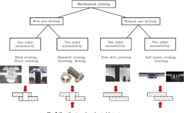
- As shown in the image mechanical joining can be classified as with pre-drill and without pre-drill which means with Pre-drill have holes and threading in it so that screws, nuts or bolts can be used in this category. Where as in without pre-drill forcible drilling or riveting by piercing will be done. The one side or two side accessibility refers in how many sides the mechanical joint can be accessible. For example, if you are using screw and nut, it can be accessible from two sides i.e. from top and bottom where as in case of riveting only from the top side is accessible and bottom side it is pierced into the metal.
- Metallurgical joining
- It joins two metals involving metallurgical changes in it. Sometimes metals will be fused or heated or filler materials may be dead etc. Welding, brazing, diffusion bonding, soldering, adhesive bonding fall into this category.
- Welding
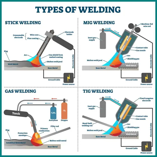
- Welding is joining process in which the workpieces are joined by melting. A common method for welding, known as arc welding, consists of generating an electric arc between an electrode and the workpiece to be welded together. The arc generates enough heat to melt electrodes and the areas of the workpiece were the welding is performed as the electrode passes over the region while the arc is present, molten metal from the electrode and molten base metal from the workpiece all get mixed together, solidifying to form a strong joint up on cooldown. The electrode contains some flux material, the purpose of which is to stabilize the arc form by generating gases that shield the arc from the surrounding atmosphere. Some types of weldins are shown in the image below.
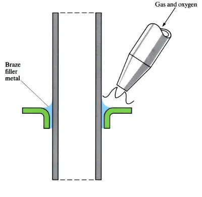
- Brazing: -
- In brazing two workpiece are joined together using a filler material that is sandwiched between them, where in only this filler metal undergoes melting without causing any melting in workpiece. The temperature for brazing should be high enough to melt the filler material, but not for the workpieces. Materials used as fillers for brazing are those that melt above 450 deg C. Flux is also used during brazing for the purpose of eliminating oxide films from the surfaces of the workpieces and preventing oxidation. This would ensure a good metallurgical bond between the workpieces and the filler once the brazing process is completed. Once melted, the brazing materials fills up the spaces between the surfaces is being joined, and even manages to get into tight spaces by capillary action. A strong joint is obtain after the brazing material has cooled down.
- Soldering
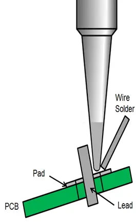
- Soldering is joining process which is performed at much lower temperatures than brazing. In soldering two work pieces joined together with a filler metal, such that only this filler metal undergoes melting, i.e., the workpieces do not experience any melting, brazing materials are those that melt above 450 deg C, so soldering materials would be those that melt at less than 450 deg C. Like welding and brazing soldering also employs flux materials to clean the surface to be soldered and improve metallurgical bonding. Residues from fluxes, however, must be removed after soldering to reduce the risk of the occurrence of corrosion.
- Adhesive bonding
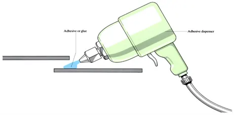
- Adhesive bonding uses bonding chemicals or metals known as adhesives. It is used to join polymers and polymer-matrix composites, polymers to metals, metals to metals, and ceramics to metals. adhesive-bonded joints can withstand shear, tensile, and compressive stresses, but they do not exhibit good resistance against peeling. High adhesive bond strength is achieved if chemical bonds are formed between the adhesive and the base material, or adherent. To improve the adhesive bonding strength, surfaces is to be joined by a adhesive must be cleaned thoroughly which minimize the interfacial gap between the adhesive and the adherent. Rough surfaces also improves adhesive bond strength because of the mechanical interlocking.
- Diffusion bonding
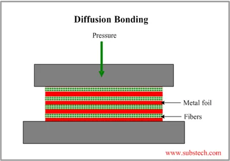
- Diffusion bonding is solid-state joining process which undergoes macroscopic deformation of work pieces. It is performed at temperatures higher than half the absolute melting point of the base material. Diffusion bonding involves two stages.
- Deformation processes of the surfaces to be joined.
- Formation of bonds by diffusion-controlled mechanism such as grain boundary diffusion and power law creep
- Diffusion bonding can be performed with various sizes of metal and ceramic parts.
- It is very slow process and it is performed at inert atmospheres to avoid oxidation. This can be done in layers by layers also.
- What is resistance welding & its application in the automotive sector?
- Resistance welding is the joining of metals by applying pressure and passage of current through the metal area to be joined. In this joining my extra material required and it is also cost effective. Resistance welding were of different types such as spot and seam, projection, flash and upset welding. The electrodes used in this welding are copper based alloys. Resistance welding machines are designed and built for a wide range of automotive, aerospace and industrial applications.
- Resistance spot welding
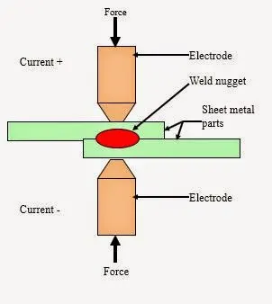
Resistance spot welding is done in spots. These spots are marked first at required intervals and the workpiece is paced between the electrodes and the force as well as power supply will be given which result in slightly melting and joining in that spot such a welding is called resistance spot welding.
Resistance spot welding is used widely in automobile industry. It is used in joining inner and outer parts of BIW structure. Apart from this there are lot of applications in automotive sector where resistance spot welding is used.
- Resistance seam welding
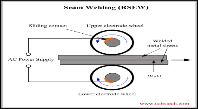
Resistance seam welding is almost similar to this spot welding but instead of spot it is performed as a whole using a circular sliding electrode. These electrodes roll along the workpiece and obtained continuous welding instead of spots. It is used for closed and no gap parts.
Resistance seam welding is used in automotive sector. The parts like fuel tanks, gas tanks and other liners or edges uses resistance seam welding. It welds without any gaps or space. this welding perfectly seals the parts. Hence wherever leak proof components are there then this welding comes into play.
- Resistance projection welding
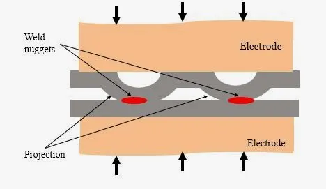
Resistance projection welding is almost similar to the resistance spot welding here the workpiece with projections are joined. Since the only contact points between the workpiece are projections. The pressure and current flows pas through the projections and joining takes place at that region such type of resistance welding is called resistance projection welding.
Resistance projection welding is used in doors assembly and in some special parts joining to the BIW structure. This welding is used.
- What is Fusion welding and types of fusion welding with its application in the automotive sector?
- Fusion welding process uses heat to join or fuse two or more materials by heating them to melting point. The process may or may not require the use of filler material. External application of pressure is not required for fusion welding processes, except for resistance welding, where substantial contact pressure is required during welding for sound joining.
- The different types of fusion welding are as discussed below
- Shielded metal arc welding
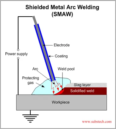
- It is also known as annual metal arc welding, flux shielded arc welding or stick welding that uses a consumable electrode covered with a flux to lay the weld. An electric current either AC or DC is used as welding power supply, that power supply is used to form an electric arc between the electrode and the workpiece to be joined. The workpiece and the electrode melts forming a molten metal pool that solidifies to form a joint. As the weld is laid, the flux coating of the electrode disintegrates, giving off vapors that serve as a shielding gas and providing a layer of slag, bopth of which protect the weld area from atmospheric contamination.
- This welding is used in the joining of base parts of the chassis and doors of the automobiles.
- Metal inert gas welding
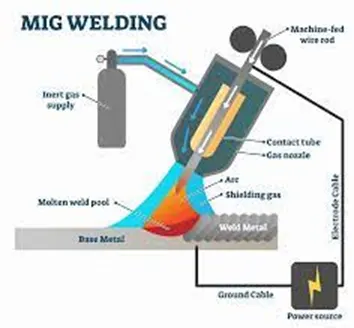
- It is also known as gas metal arc welding or metal active gas welding in which an electric arc forms between a consumable wire electrode and the workpiece leading them to melt and join. Both use a shielding gas to protect the weld from airborne contaminants, or oxidation in the case of MIG welding. The process can be semi-automatic or automatic. A constant voltage and direct current power source are most commonly used with GMAW. But constant current systems, as well as AC, can be used. There are four primary methods of metal transfer in GMAW, called globular, short-circuiting, spray, and pulsed spray, each of which has distinct properties and corresponding advantages and limitations.
- This welding is used in the joining of bone, chassis area and engine parts in automotive industries.
- Tungsten inert gas welding
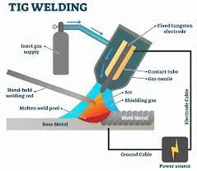
- This is an arc welding process uses a non-consumable tungsten electrode to create the arc between the electrode and the base plate. An inert shielding gas is used to protect from oxidation or other atmospheric contamination. A constant current welding power supply produces electrical energy, which is conducted across the arc through a column of highly ionized gas and metal vapors known as plasma.
- TIG welding is most commonly used to weld thin section of stainless steel and non-ferrous metals such as aluminum BIW fixtures of automobile.
- Plasma arc welding
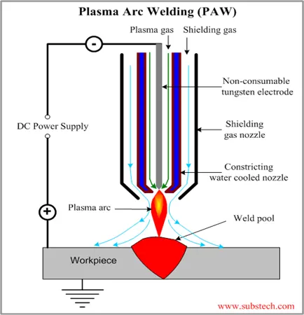
- This process uses an electric arc created between an electrode and the torch nozzle. The electric arc ionizes the inert gas in the chamber creating what is called as plasma. It is then forced to through a fine bore copper nozzle that constricts the arc and direct it to the workpiece, allowing the plasma arc to be separated from the shielding gas.
- In automotive industry, plasma arc welding was used for several purposes.
- What is the 3-2-1 principle?
- During metalworking process, it is very much important to locate the parts to be work relative to do work fixtures. Any variation in part location on the fixture adds to the dimensional tolerance that must be assigned to the finished parts. The method of supporting and securing the part in the fixture affects not only dimensional tolerances, but surface finishes as well. Techniques for supporting and clamping must be considered together with their method of locating in order to assure repeatedly from Part-to-part. The basic principle of fixture is to restrict all degrees of freedom in the desired location and orientation.
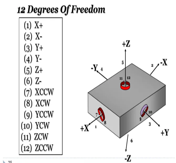
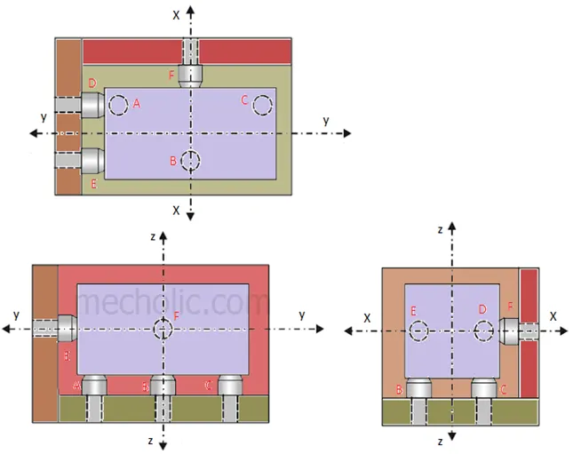
- As shown in the above image degrees of freedom are 12 in that there are 6 transitional degrees of freedom and 6 rotational degrees of freedom.
- pins A, B, C in the above image on the base plan restrict the rotation of component above X axis and Y axis. It also limits the downward movement of component along Z axis. Le 1, 2, 3, 4 and 5 degrees of freedom is restricted. Pins D, E is in plane parallel to the plane containing. X and Z axes. It prevents the rotation of component about Z axis and the movement of the body in along Y axis toward one direction. The last pin F is in plane parallel to plane contains Y and Z axis. It restricts the movement component along X axis in one direction. Three remaining degree of freedom 10, 11, 12 is unrestricted. It facilitates the loading of the component in the fixture. These three degrees of freedom may restrict after loading of component by using clamping devices.
- Define body coordinates system?
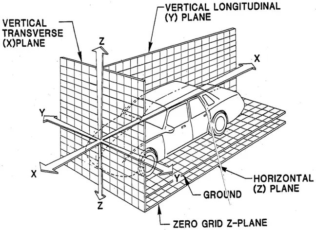
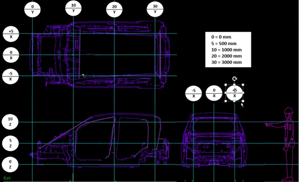
- Body coordinate system is also called as car line or body line coordinate system is a reference system consists of set of points, lines and surfaces are used to define position of point in space either in two or three dimensions.
- Maintaining X, Y and Z coordinates in fixture is a very important factor. We should try that the co-ordinates of locating and clamping points should not be in three decimals. They should be in the whole nos. or max up to one decimal. Once these coordinates are maintained automatically the BIW bas structure is maintained.
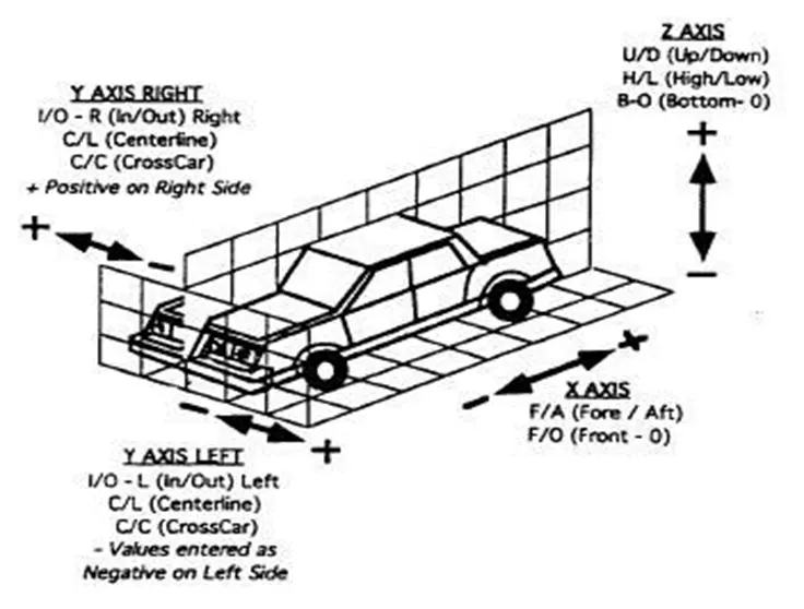
- All vehicle product drawings are defined numerically relative to three vehicle planes. Description shown below.
- (X) it is in width of BIW – OX is body center line
- (Y) it is in length of BIW – OY is near front bumper
- (Z) it is in length of BIW – OZ is about center of the wheel
- Elaborate body plane system & its essentials?
- Body planes are three mutually perpendicular imaginary planes. These are reference planes in automotive car. These are used to define GD & T of all parts in automotive domain. The measurement from body plane to parts are called body plane dimensions.
- Body planes are essential for because
- It defines exact position of each product in the vehicle w.r.t. a fixed origin.
- It ensures flawless design for assembly.
- While designing lines, all the designs are carried out relative to the bodylines viz.fixture, turntables etc.
- It assists in easy location of different parts in the vehicle.
- It aims in creating a standardized system.
- It assists in quality checks.