Week 2:- BiW Fixture Basics Challenge
1.............................
PROCESS OF PROJECT EXECUTION ACTIVITY:
Project activities involve all the activities from the RFQ (Request for Quotation) received from the customer to the Dispatch of Fixtures from our side.
A request for quotation (RfQ) is a business process in which a company or public entity requests a quote from a supplier for the purchase of specific products or services. Customer requests a quote of a sub assembly, geo-fixture, respot fixture or checking fixture from supplier. In this, he expects the supplier to mention the cost involved and the time taken to complete the project.
Offer Submission is done once we receive RfQ from the customer based on which we make our offer. this involves technical offer and commercial offer.
Technical offer
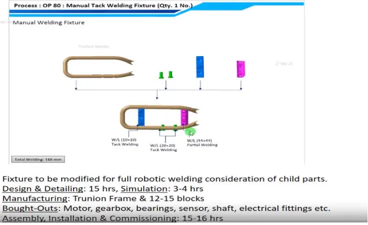
In technical offer, suppose we ger a sub assembly fixture on which a part of total assembly is to be welded, then, we mention the all the components that are to be welded on a particular station. Also, we mention the welding length of each component and also the total welding length as shown above. In the above offer, we have mentioned that 5 component will be welded on OP-10 station in which we have mentioned welding required for each component along with their welding length. The total welding length is also mentioned. We have also mentioned the activities involved in the development of fixture and time taken for each activities. this is done so that the customer has an idea as to when the project can be completed and also helps in deciding the cost of fixture. The processes are
Design and Detailing:- 15 hrs
Simulation:- 3-4 hrs
Manufacturing:- Trunion Frame & 12-15 Blocks(required in trunion frame)
Bought -Outs:- Motor, gearbox, Sendors, Shaft, Electrical fittings etc.
Assembly, installation & Comissioning:-15-16 hrs
Based on this a commercial offer is made, So if design costs x Rs per hour and Simulation costs y Rs per hour. Then Cost of design and simulation would be 15x+4y
We submit the Technical offer and Commercial Offer to the customer for their understanding.
Customer gets similar offers from other suppliers also and he compares the offers on basis of cost and some other parametres. Then he releases a PO (Purchase Offer) to start work. Along with purchase offer, we will also get input data like 3D panel data of Car panel, Designing Standards and 2D standards.
On receiving the Purchase offer, we begin scheduling all the activities that need to be done in order to finish the project. We also mention the time required for each activity and a deadline for each so that we can finish each activity in time.
Delay in one activity can cause a delay in others because each activity can only be done when the preeding activity is completed. For example, we cannot start the simulation of fixtures until we have completed a 3D concept in Design. Similarly we cannot manufacture until the Quality has checked each drawing and approved for manufacturing. The activities in volved in schedule preparation are mentioned in chronological order below:
01) PO Received
02) Kick Off- Process design
03) Design Data Study
04) 3D Design preparation
05) Simulation
06) Final DAP
07) BOP release
08) BOP Indent
09) BOP Ordering- bought Out Parts
10) Robot Cell Drawing Release
11) Raw Material Release
12) In house part Manufacturing
13) QC Inspection
14) Painting
15) Pneumatics installation
16) Controls
17) CMM prove Out
18) Part fitment Trial
19) Dispatch planning
20) Installation
21) Electrical Integration Onsite
22) Robotic programming
These activities are common for mostly all projects but there is a change in timeline of each activity depending on the scope and magnitude of project.
After Schedule Preparation,we move onto BOM preparation in which we mention the gearboxes, cylinders that we will require for the project.
Then, we design 3D Concept based on data given by customer in PO.
Then DAP(Design Approval process) is done in which customer takes a look at the concept and suggests modification, if required, modification can be increase in number of clamps or pins. We send the data after modification to the customer for approval.
Then, we release all the drawings for manufacturing of parts and also release Boughtout parts like Cylinders, Bushes, Sensors, Hardwares, Standard parts like Sensor brackets, shims etc. It is advised that we do a self QC before releasing the drawing. We can achieve this by making a checklist of things that need to be checked like dimentions, tolerances and overall dimentions. Each dimension is important and each misssing dimension can cause confusion in the mind of a person who is manufacturing the part which will increase the time taken and cost of the project.
After manufaturing of parts, Quality Control Department checks each manufactured part and checks if it is as per the drawing. This is important as any error at a later stage can cause time wastage and we might need to disassemble and reassemble the whole fixture.
After this, all the electrical connections are done and CMM inspection is done to check if the positions of the parts at assembly are same as that in the design. Coordinates are checked for mylars and pins as they are in direct contact with the panel.
After CMM inspection, internal trials are performed which means that the panels that are to be welded are placed on the fixture and checked if the pins are getting into the holes and panel is getting clamped properly.
After Internal trials, online trials are performed with all the sensors, sequencing and controls. It is checked whether everything is being done as per the process. The successful completion of online trials is conveyed to the customer.
Further, Installation is done as per the layout consisting of robots and Fixtures at their respective positions placed accurately as depicted in the layout.
Next, we start the packaging of the fixtures and this is important because improper packaging can damge the fixture aesthetically and can affect its functioning.
In the next step, Trials are performed at customer end. this is important as it needs to be checked whether we are delievering as promised, whether the quality of panels that are produced is up to the mark or not. Also, if we have promised that 100 panels can be welded in 8 hrs shift, we need to achieve the production target.
After sucessful completion of the production trial, we provide training to the staff at the customer end to explain them the process and sequence.
Buyoff meeting
Buyoff meeting is done in which customer checks everyhing and if there are anything missing,customer can raise the point and we need to do that. Also, if customer wants something added, a new PO is generated.
Finally, we handover the fixtures to the customer.
Process involved in Design
In design, there are two types of Industries
Line Builders-
They take orders from customers like Geometric Fixtures, Respot Fixtures, Checking fixtures and sub -assembly fixtures and are responsible from design to manufacturing of fixtures.
Design Industry-
They are companies which take projects from Line Builders and provide design and simulation services. They are responsible for Design and detailing as per customer standards and simulation validation along with documentation.
In Design Process, we divide project into different activities because each step is important and next step is dependant on the previous step.
First we need to study the Data Input we have received and study each and every step in that so that there is no confusion at a later stage.
If the process is taking time, it means that it requires more man power, hence increasing the cost.
Once all data is understood and process is understood, we can proceed easily and fluently.
3D Concept design
3D concept involves loading of panel, clamping and sequence of spots, calculating cycle time and number of stations and robots required to achieve that cycle time, spot plan of panel.
The above image shows the spots taken by diffrent robots at different stations. While designing, we have to consider all the aspects of spot plan. If we do not take care of these constraints, then at later stage, we will have to change the design which will increase the time and effort. Here it is clearly mentioned that certain spots are taken by Robot 1 and others are taken by robot 2. This is important to use 2 robots as robots number is chosen in order to achieve the required cycle time as per production.
Simulation Validation
In this, we have to check for proper gaps between the gun and fixtures. There should be no clash. If there is any clash, feedback will be given to design for changes in cocept.
QC Check
QC will check if the design has been made as per the standards of customer. Also, he will check if the design can be modified and made in some better way. Then, after the modifications are done, it is again given to simulation for validation.
Customer review
After this, we will show the design to the customer and he will check and if he approves then we proceed with the detailing as per the customer .
Detailing
Here, we will do all the detailing as per the customer standards and provide dimentions and tolerances. It is recommended that we do a self QC of the drawing by keeping a checklist of items that need to be checked before releasing to minimize errors.
Delievery
Finally, we deliver the 3D and 2D data along with documents like Clamp Validation, Sequence Sheets, pokayoke Sheets, Charts, BOMs and ergo docs.
.
.
.
.
.
.
2...........
Types of the Joining Process:
There are two types of joining processes
1.Mechanical Joints
2.Metallurgical Joints
The durability and structure of any structure is dependent on the strength of joints. We cannot make the whole structure in one piece. Joining is classified into Metallurgical Joining and Mechanical Joining. Metal Joining is a process in which two or more metals are joined together either temporarily or permanently with or without the application of pressure or heat.
a.Self- Pierced Riveting
It is a metal joining in which two similar or dissimilar metals are joined using a semi tubular rivet which clinches the sheets in a mechanical joint. It does not require pre drilled holes, which makes this process very fast. It is widely used in Automobile and Aerospace Industry. It is used at places where we require permanent/Semi-permanent welding or bolting is not an option. It is mostly done for low thickness sheet metals and Aluminum. Aluminum has low wedabilty and hence, we use riveting techniques to join it.
b.Bolting
Bolting is a joining process which is used for assembly of different parts that are to be joined temporarily and whose joints require periodic maintenance. On bolting joints, mainly two kinds of loads act, shear and tensile. In this process, (bolt/screw) (and/or nut) are used to join the two parts. In case of joining with help of a screw, one of the two parts to be joined has a clear hole and the other part has a tapping. Both the clear hole and the tapping are kept concentric for the screw to tighten accurately an easily. For the ease of installation and removal, bolting access is an important factor that needs to be taken care of. Spring washer is place between the nut and the bolt for the assembly to keep a tight fit against each other and to prevent loosening due to vibrations in the fixture.
There are three types of Bolting Joints:
1.Screw Joint
2.Bolted Joint
3.Stud joint
c.Hemming
Hemming and seaming are two similar metalworkingprocesses in which a sheet metal edge is rolled over onto itself. Hemming is the process in which the edge is rolled flush to itself, while a seam joins the edges of two materials.
d.Adhesive Bonding
Adhesive bonding is used at places where we require to join surfaces with a smoth bond.This process involves epoxies, glues or various plastic agents that bond by evaporation of a solvent or curing a bonding agent with heat, pressure and time. This joining process can take shear loads easily compared to tensile loads.
e.Welding
It is a permanent joining process in which two or more metals are joined together by application of heat and pressure(sometimes). The heat produced in this process melts the two metals and fuses them together which results in a strong joint. Heat can be applied applied electrically or with the help of a welding torch. Welding is widely used in the construction of BIW of a car. In welding, there are different kinds of joints mentioned as follows:
Lap Joint
Butt Joint
T Joint
Corner Joint
Edge Joint
Depending on the process, welding is classified into various types.
Resistance Welding is widely used in Automotive Industry as a technique to join metals together. High current is passed through two metals to be joined and heat produced is used to weld the components at localized areas predefined by the design of electrodes. Pressure is applied before and after the current is passed to confine the weld area at the particular weld interfaces.
Types of Resistance Welding:
Resistance Spot Welding
In this welding, a weld nugget is formed between two metal sheet components which are pressed against each other using Copper-Chromium or Zirconium electrodes which carry high current causing heat generation at interface between two sheet metal components. A spot weld can be achieved in a few seconds and its quality depends on quality of RSW. A BIW of a car contains 5000 spot welds. It is highly adaptable to the robotic techniques. Resistance spot welding is the principle joining method used in automotive industries and has been for many years.
Resistance Seam Welding
In this technique of welding, rollers are used as electrodes and series of spot welds are generated as rollers are in point contact with the sheet metal componnts. This welding is used at places where we cannot afford to have leakages. This welding technique is used to weld heat exchangers, radiators and containers.
Resistance Projection welding
It is used to weld sheet metal components with projections. These projects can be natural or manually made. Currrent passes through the projection part of sheet metal in contact and melts it and pressure is applied using specially designed electrodes depending on the shape of workpiece. It is mainly used for fixing autobody components eg. Weld nuts
Arc Welding
Arc Welding uses an electrode(consumable/non-consumable) to weld two components. The arc produced between the electrode and workpiece using AC or DC supply welds the two components together. Arc Welding is of following types:
Manual Metal Arc Welding
In Manual Metal Arc welding(MMA or MMAW) or Stick Welding uses an electrode which is flux coated and workpiece to create a arc. Both rod and surface material melt to create a weld.
Gas Shielded Metal Arc Welding(Metal Inert Gas(MIG))
It is an arc welding technique in which a consumable electrode is used to weld two metal sheet components together. MIG uses a consumable electrode, DC or AC Supply, Inert Gas Supply.
Shielding gas is used to prevent the weld pool from contamination. Contamination can affect the quality of weld. Shielding Gas also acts as a carrier of Filler Metal in the form of droplets. Shielding gases include 100% CO2 or a mixture of CO2 and Argon. A 75 percent Argon And 25 Percent combination of inert gas acts best for the visual quality of weld.
Gas Shielded Tungsten arc Welding(Tungsten Inert Gas(TIG)Welding)
TIG Welding also called GTAW uses a non consumable electrode to weld metals together. It is very similar to MIG welding. Weld area is protected by a shielding gas preferably Argon. It is called heliarc welding when helium is used as a shielding gas. This a complex process because it involves both the hands engagement as the filler rod is to be separately fed into the weld area and it is also slow compared to other welding techniques. filler material depends on the nature of workpiece Tungten has high melting temperature, hence, it remains unaffected during the welding process although some wear and tear can occur. TIG Welding can produce highest quality welds if done by a skilled welder. This welding technique became popular in 1940 as it could join magnesium and aluminum together.
In any welding process, our aim is to maximize the quality of weld by removing defects. A welding defect is a flaw that compromises on the usefulness of a weldment. These defects are mentioned below:
1. Lack of Fusion
2. Porosity
3. Undercut
4. Lack of/ Excess Penetration
5. Non Inclusion(Tungsten/Copper/Slag)
6. Weld Crack
To test the weld strength, various tests are advised. They are stated as follows:
1. Visual Inspection
2. Dye Penetration Test
3. Ultrasonic Test
4. Laser Inspection
5. Radiography
6. Acid Etch test
Brazing
It is a process in which an alloy or a filler metal is heated above 450 degrees and melted. The Base metal is heated and filler material is distributed between two close fitting parts using capillary action. The filler metal melting point is always lower than the parts being joined together. It can join dissimilar metals as well. It is a commercially accepted process and is used in wide range of applications due to its integrity to which joints may be produced and flexibility.
Advantages:
A) Dissimilar metals which can’t be joined by welding can be joined by brazing
B) Very thin metals can be joined
C) Metals of different thickness can be joined
Soldering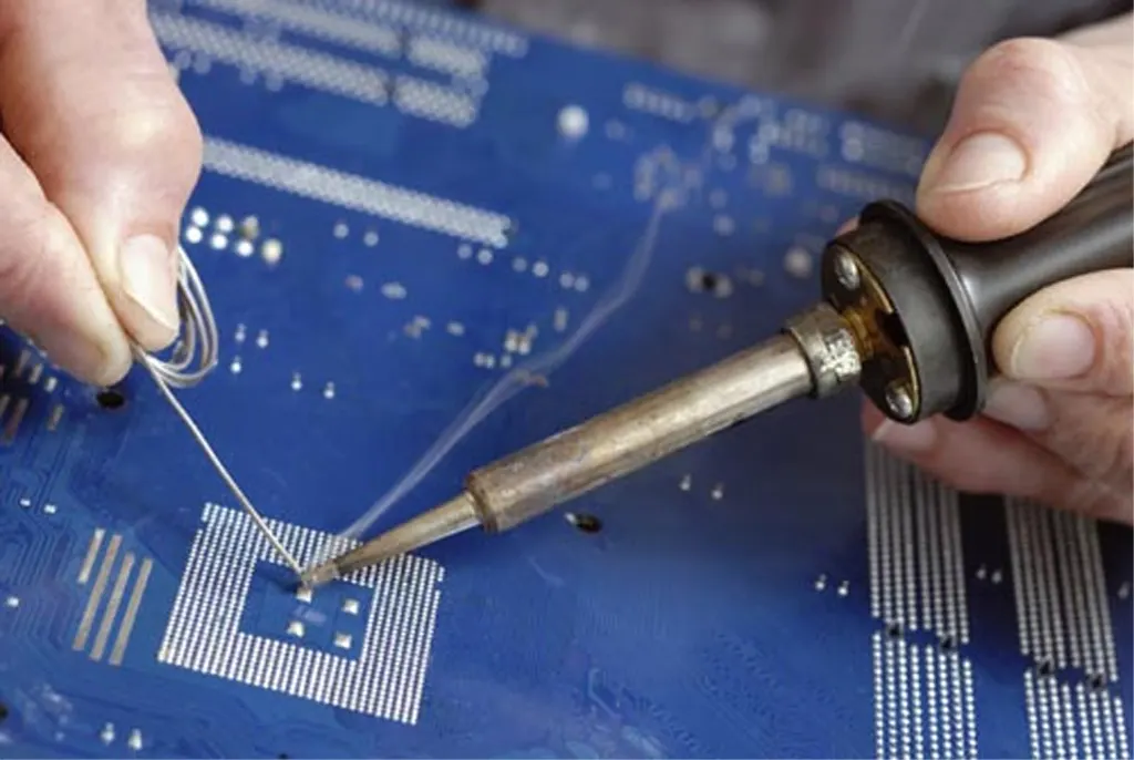
Soldering is a process in which two or more metal items are joined together by melting and then flowing a filler metal into the joint—the filler metal having a relatively low melting point. Soldering is used to form a permanent connection between electronic components. In this soldering process, heat is applied to the parts to be joined, causing the solder to melt and to bond to the workpieces in a surface alloying process called wetting. In stranded wire, the solder is drawn up into the wire between the strands by capillary action in a process called 'wicking'. Capillary action also takes place when the workpieces are very close together or touching. The joint's tensile strength is dependent on the filler metal used; in electrical soldering little tensile strength comes from the added solder which is why it is advised that wires be twisted or folded together before soldering to provide some mechanical strength for a joint. A good solder joint produces an electrically-conductive, water- and gas-tight join.
.
.
.
.
.
3.
Resistance Welding & its application in the automotive sector:
Resistance Weldingis widely used in Automotive Industry as a technique to join metals together. High current is passed through two metals to be joined and heat produced is used to weld the components at localized areas predefined by the design of electrodes. Pressure is applied before and after the current is passed to confine the weld area at the particular weld interfaces.
Types of Resistance Welding:
Resistance Spot Welding
In this welding, a weld nugget is formed between two metal sheet components which are pressed against each other using Copper-Chromium or Zirconium electrodes which carry high current causing heat generation at interface between two sheet metal components. A spot weld can be achieved in a few seconds and its quality depends on quality of RSW. A BIW of a car contains 5000 spot welds. It is highly adaptable to the robotic techniques. RSW is the dominant metal sheet joining process in the automotive industry because of minimum skill requirements, inexpensive equipment, ease of control, its versatility, high operating speeds, repeatability, suitability for automation or robotization and inclusion in high production assembly lines.
Resistance Seam Welding
In this technique of welding, rollers are used as electrodes and series of spot welds are generated as rollers are in point contact with the sheet metal componnts. This welding is used at places where we cannot afford to have leakages. This welding technique is used to weld heat exchangers, radiators and containers like fuel tanks.
Resistance Projection welding
It is used to weld sheet metal components with projections. These projects can be natural or manually made. Currrent passes through the projection part of sheet metal in contact and melts it and pressure is applied using specially designed electrodes depending on the shape of workpiece. It is mainly used for fixing autobody components eg. Weld nuts
.
.
.
.
.
4.
Fusion welding & types of fusion welding with its application in the automotive sector:
Fusion Welding is a process that uses heat to join or fuse two or mare materials by heating them to melting point with or without the use of filler material. Unlike Resistance welding, this process doesn't require application of pressure. Fusion welding is used in the manufacture of many everyday items including airplanes, cars, and structures. It is of following types:
1. Arc Welding
2. Laser Welding
3. Induction Welding
4. Oxy-Fuel Welding
5. Solid Reactant Welding
1. Arc Welding
In this welding technique an arc is formed between the workpiece and welding torch. A filler material is fed into the arc and the melting of filler metal forms the bond between the metals to be joined. This process is widely used as it makes strong and aesthetic welds. Arc welding machines are portable and can reach hard to weld areas. They can be taken to sites where welding needs to be performed. Arc Welding is the most common welding technique in underwater welding. During underwater welding, a pool of gas is formed around the area to be welded. This technique is applied in Ship Hulls repair and oil Rig maintenance.
Types of Arc Welding:
Manual Metal Arc Welding(MMAW)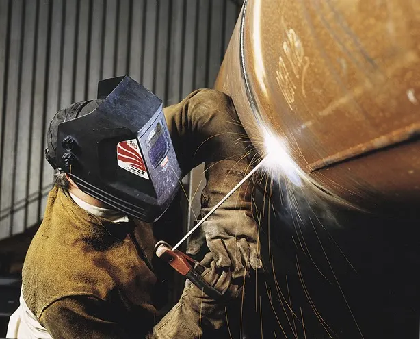
In Manual Metal Arc welding(MMA or MMAW) or Stick Welding uses an electrode which is flux coated and workpiece to create a arc. Both rod and surface material melt to create a weld.
Gas Shielded Metal Arc Welding(Metal Inert Gas(MIG))
It is an arc welding technique in which a consumable electrode is used to weld two metal sheet components together. MIG uses a consumable electrode, DC or AC Supply, Inert Gas Supply.
Shielding gas is used to prevent the weld pool from contamination. Contamination can affect the quality of weld. Shielding Gas also acts as a carrier of Filler Metal in the form of droplets. Shielding gases include 100% CO2 or a mixture of CO2 and Argon. A 75 percent Argon And 25 Percent combination of inert gas acts best for the visual quality of weld.
Gas Shielded Tungsten arc Welding(Tungsten Inert Gas(TIG)Welding)
TIG Welding also called GTAW uses a non consumable electrode to weld metals together. It is very similar to MIG welding. Weld area is protected by a shielding gas preferably Argon. It is called heliarc welding when helium is used as a shielding gas. This a complex process because it involves both the hands engagement as the filler rod is to be separately fed into the weld area and it is also slow compared to other welding techniques. Filler material depends on the nature of workpiece. Tungten has high melting temperature, hence, it remains unaffected during the welding process although some wear and tear can occur. TIG Welding can produce highest quality welds if done by a skilled welder. This welding technique became popular in 1940 as it could join magnesium and aluminum together.
2. Laser Beam Welding
Laser Beam Welding also called Conduction Welding or Radiation Welding is a highly precise welding technique. LASER is abbreviated as Light Amplification by Stimulated emission of Radiation. The beam provides a concentrated heat source, allowing for narrow, deep welds and high welding rates. Light is emitted in the form of bursts called pumps. These bursts of light are channeled along a seqm at the workpiece to be melted and welding is performed. It creates multiple welds at once. The pumps can be split and directed at different directions, which reduces the cost. Laser welding has application in the Automotive industry. The applications of laser in the manufacture of components cover engine parts, transmission parts, alternators, solenoids, fuel injectors, fuel filters, air conditioning equipment and air bags. In the comin years, it is a direct replacement for resistance spot welding or adhesive bonding, where lap joints or hem flange joints are utilised on pressed components for body-in-white assembly. Laser welding is also being applied in the production of partial penetration welds, for example, in hem flanges often used in doors, bonnets, boot lids and other closures.
3. Induction Welding
Induction Welding is a form of resistance welding in which there is no contact between the workpiece and the source. A coil is wrapped around the workpiece to be welded and a high radio frequency cureent is passed through it. The eddy currents produced in the workpiece cause the heating effect due to resistive heating. Plastic materials can also be induction welded by installing ferromagnetic or metallic conductors. Induction welding of carbon fiber reinforced plastics is commonly used in the aerospace industry. Induction welding is used for long production runs and is a highly automated process, usually used for welding the seams of pipes. It can be a very fast process, as a lot of power can be transferred to a localised area, so the faying surfaces melt very quickly and can be pressed together to form a continuous rolling weld.The depth that the currents, and therefore heating, penetrates from the surface is inversely proportional to the square root of the frequency. The temperature of the metals being welded and their composition will also affect the penetration depth. This process is very similar to resistance welding, except that in the case of resistance welding the current is delivered using contacts to the workpiece instead of using induction. This welding is used to make engine parts such as valves, crankshafts, camshafts, connection rods, starter rings and transmission parts, for example CV joints, tulips and axle shafts.
4. Oxy-Fuel Welding
In oxy fuel welding commonly called Gas Welding, a flame of gas is used to weld the metals together. The temperature of the tip of the flame reaches around 2500 celcius and 2500-3000 celcius at the inner core of the flame. In oxy-fuel welding, a welding torch is used to weld metals. Welding metal results when two pieces are heated to a temperature that produces a shared pool of molten metal. The molten pool is generally supplied with additional metal called filler. Filler material selection depends upon the metals to be welded. Oxy Fuel flame uses a mixture of oxygen and acetylene filled in the cylinders under pressure. Apart from acelylene, propane and methanol can also be used but Acetylene is most widely used gas. Before the invention of Arc welding, Gas welding was the only welding which was used to weld all kinds of materials like carbon steel, alloy steels, cast iron, aluminium, and magnesium.Oxy-acetylene welding is still used for metal-based artwork and in smaller home-based shops, as well as situations where accessing electricity. Although in many industrial operations, it has been superseded by Arc Welding due to its high speed and ability to weld highly reactive metals like titanium. It is used in Automotive Industry to weld parts of frame and chassis and is widely used in the Automotive repair works as thin to medium sheet metals are easily weld using gas welding.
5. Solid Reactant Welding
There are many elements and compounds which when react with each others under specific conditions or in presence of a catalyst produce enormous amount of heat. These reactions are called exothermic reactions. These compounds when channeled to the two metals can join them using the heat produced. The heat produced melts the two metals and these metals join together forming a strong bond on cooling. It requires no external source of heat or current. For exmple, Thermite is a compound made up of a metal oxide and Aluminium. The reactants are commonly powdered and mixed with a binder to keep the material solid and prevent separation. The weld quality of chemically pure thermite is low due to the low heat penetration into the joining metals and the very low carbon and alloy content in the nearly pure molten iron. To obtain sound railroad welds, the ends of the rails being thermite welded are preheated with a torch to an orange heat, to ensure the molten steel is not chilled during the pour. Solid reactant welding is widely used to weld railway rails.
.
.
.
.
.
5.
3-2-1 Principle:
3-2-1 principle is devised to arrest all the 12 degrees of freedom of a workpiece on which an operation like milling, welding, turning is to be performed.
The three rests at the bottom surface arrest the following
4 Rotational(XCCW,XCW,YCCW,YCW) and 1 translational(-Z) DOF. i.e 4+1=5
Two locators or pins arrest the following:
2 Roational(ZCCW,ZCW) and 4 Translational(+X,-X,+Y,-Y) DOF i.e 2+4=6
1 Clamp arrests the final +Z DOF=1
Total degrees of freedom arrested= 5+6+1=12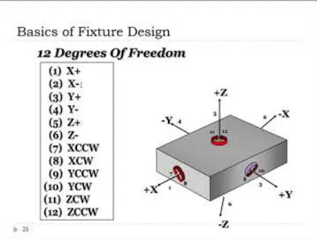
In welding fixtures,For 3 supports we use mylars or NC Blocks that are in direct contact with the panel. They are made of C45, Nylon or S45C. These materials are cut in shapes as required according to the drawing and flame hardened to increase their wear resistance as repeated contact with panels can wear down their contact surfaces leading to geometrical inaccuracies. Three supports are used because we need 3 points to create a plane. Equation of Plane is
XY+YZ+ZX=0
Two pins are given in such a way that removal of panel happens without any damage to the panel. This can happen when the axes of the two holes are parallel to each other. On the other hand, if the axes of the holes are inclined with each other, we need to replace one of the stationery pin with a retract pin unit.
A clamp is given on the top of panel to restrict final translational degree of freedom. This is done so that the panel does not move when a gun comes and welds a spot. The force of the clamp is enough to sustain the force exerted by the gun. Also, the clamp only holds the panel and does not apply pressure on it.
For a fixture designer, the major part of the time goes into deciding how to locate the component properly and accurately. Keeping 3-2-1 principle in mind, all the fixtures are designed. This reduces the time taken to perform a particular operation on multiple components, hence, reducing the cycle time and reducing the cost. Various types of fixtures (like drilling fixtures, milling fixtures, and welding fixtures) are used in industry. The 3-2-1 method is the fundamental principle for all types of fixture design.
.
.
.
.
.
6.
Body coordinate system:
A coordinate system is a reference system consisting of set of points, lines and planes used to define points in space in either 2 or 3 directions.
Body Coordinate system refers to the coordinate system that a car follows so that it is easy to locate the postion of a particular part or panel. I general, Body Coordinate System is also called Car Line or Body Line. A car BIW is made up of numerous panels that are welded together using different welding techniques. Welding of Car Panels happens at Assembly lines. These panels are welded at different zones(Front body, Side Body, Rear Body) and each zone is further divided into stations like Dash Assembly, Rear Floor, Side Doors, Under body, Rear Floor. Now it becomes tedious to guess where the panel will be installed in the car body.
X= LONGITUDINAL DIRECTION[(FORE & AFTER-F/A) OR (Front O Line-FOA)]
Y= TRANSVERSE DIRECTION[(CROSS CAR-C/C) OR (Centre O Line-COL)]
Z= VERTICAL DIRECTION[(UP & DOWN-U/D) OR(Bottom O Line-BOL)]
Origin of Body Coordinate System(OX) lies at the front cenre of the car. In some manufacturers it also lies somewhere near the engine along the X direction. It indicates the length of the car and coordinate system OZ's starting point lies at the bottom of the car and indicates the height of the car and finally, Coordinate system OY's starting point lies in the centre of the car and indicates the width of car. While designing lines, all designs are carried out relative to the body lineviz. fixtures, turntables etc. It also assists in quality checks as CMM can easily locate the position of actual car panel with the help of tooling holes and can tell if the car panel is at its right position.
In the above Panel, we are checking the coordinates of the panel and trying to guess the location of the car part. Coordinates are:
X= 4042
Y= -38
Z= 1087
Note that all dimentions are in mm
+X dimension means that the component lies towards rear from the car origin at a distance of approximately 4 metres. Since cars are around 4 metres to 5 metres long, we can assume that it lies at the rear end.
-Y dimension indicates the direction towards the left of car but since the distance is only 38mm we can assume it to be in the centre.
+Z dimension indicates that the component is aroud 1 meter from the car origin in the Z direction which means it is not very high from the ground.
Hence, we can conclude that this can be a Rear Floor Panel.
.
.
.
.
7.
Body plane system & its essentials:
Body Planes are Automotive Planes in a car. These planes are used to define the Geometric Dimentioning and tolerancing of alll car parts in Automotive Domain. They are three mutually perprndicular planes which are usually located either at the front end of the car or near the Engine portion of car. Like any coordinate system, the zero of the planes is considered at a point where all three planes intersect. The distance of car parts from these planes are called Bodyline or carline dimensions. They are named as follows:
*Front O Line(OX)
*Centre O Line(OY)
*Bottom O Line(OZ)
*Measurement along Front O Line is called F/A Front Aft
*Measurement along Centre O Line is called C/C Cross Car
*Measurement along Bottom O Line is called U/D Up Down
Car Lines have many advantages as Stated below:
It defines exact position of each component in a vehicle with respect to a fixed origin.
It assists in Quality checking of panels for dimentional accuracy.
It aims at creating a standardisation of process.
It ensures flawless design in assembly..