Week 2:- BiW Fixture Basics Challenge
1) Project Execution Activity
1. RFQ:
- RFQ – Request for Quotation.
- In this where the customer gives the requirement/specifications in detail for the given projects in the form of data or documents.
- Also, the customer specifies its technical offer, commercial offer, etc, how the project will be executed & the timeline of the project also will be mentioned.
2. FIRST SPEC: DISCUSSION MEETING:
- After RFQ received, Technical offer, commercial offer, a timeline of the project, etc, will be discussed and prepared from outside.
- In this time required for data study, 3D design concept, simulation validation, quality check, 2d drawing release, bought-outs, manufacturing, assembly, installation & commissioning will be discussed and prepared in the technical offer.
- Based on the technical offer, the commercial offer will be finalized.
3. OFFER SUBMISSION:
- After the finalization in the meeting, the offers will be submitted to the customer end. The customer will arrange to get an offer from other suppliers too.
- Based on the technical, cost, quality, standard, and name in the industries, the customer will be finalizing the offer.
4. LOI/PO RECEIPT:
- After an offer has been finalized customer will be releasing the LOI/PO (Purchase Order). Once PO is released, we have to start the work.
- After getting the PO from the customer, we have to prepare the schedule.
5. SCHEDULE PREPARATION:
- Once the PO released from the customer, we will be working on the preparation of the schedule which should be matched our planned commitment in the technical offer/customer required time.
- Schedule preparation is nothing but dividing the different activities like kick-off meeting, design data study, DAP, simulate, Quality check 2D detailing, drawing check, Release of BOM, Manufacturing, bought outs of electrical & mechanical components, Assembly of the fixture, paint, trial run out, installation and commissioning at the customer end, etc.
- These activities will be traced in the schedule preparation chart.
- The date-wise schedule should be matched the committed date. Otherwise have to revise the schedule and prepare accordingly by discussing it in the meetings.
6. BOM PREPARATION:
- Bill of materials like cylinders, motors, etc, which are required for the project are prepared.
7. DESIGN CONCEPT PREPARATION:
- Before design concept, we have to study the data of consumer requirements thoroughly which is carried out in design data study activities.
- During the design data study, we will proceed with rough sketches to get a flow while designing concepts.
- The concept preparation would include the process like load act on panels, clamping process, which spot should be welded first, travel of the gun.
- In this concept preparation, we should conceptualize the basic data like spot plan, cycle time, etc,
- The weld gun should not collapse while traveling, so by considering this have to make a concept preparation.
- To avoid collapses of weld guns or robots during traveling, a spot plan will be done at the initial stage.
- In design concept preparation, the design of the layout is been prepared at a very initial level which gives the information of placements of robots and fixtures.
- Spot plan should be taken into consideration during concept design preparation
- The spot plan clears us that how many robots are to be used and the sequence of the spot will be decided along with which robot will be cover certain spot places.
- Also, the cycle time should be considered while preparing the concept design. To calculate the cycle time, we should go to the cycle time study.
- Cycle time study includes min per shift, No. of shifts, No. of days per year, No. of component per year, the total number of minutes.
- Cycle time study includes min per shifts, no. of shifts, no of days per year, no of component per year, the total number of minutes, efficiency, Total no of seconds, take time seconds, average time per spot, total no of spot, no of robots placed. From the cycle time study, we can get time taken per spot, time is taken for a single component, efficiency of production. If the efficiency is not satisfied, we have to do some reconsideration in the design.
8. CUSTOMER APPROVAL:
- It is also known as the Design Approval Process (DAP).
- After design concepts, the customer will review the design concepts.
- If the design needs to be made simple or some other correction needs to be done in concept design will be discussed and after meeting the requirement of the customer, they will give approval to the design to go on with further activities.
9. DETAILING & DRAWING RELEASE:
- Once the customer approved the process, the detailing of the fixture parts which is to be manufactured has been done by giving appropriate dimensions and GD&T symbols.
- All the dimensions which are necessary for manufacturing should be included with GD&T in the drawing before releasing the drawing to the manufacturing team.
10. MANUFACTURING/BOP ORDERING:
- The mechanical & electrical parts like sensors, cylinders, etc, which needs for a fixture are ordered as per design specifications.
11. MECHANICAL / ELECTRICAL ASSEMBLY:
- After the materials ordered received to our end. The quality will check the working conditions and technical specs, which meets our requirement.
- After the quality check, the mechanical & electrical parts are assembled as per design.
12. QUALITY INSPECTION:
- After the assembly again the quality check is done.
- In all dimensions, positional accuracy, coordinates are checked using CMM.
13. INTERNAL TRIAL:
- After QC check, internal trials are made to check the operation of the fixture.
- It is the first trial taken in-house, so we will see by putting the assembly in the fixture whether the seating of assembly/panel suited correctly, whether the clamping operation is done properly, also whether the pins are getting into the holes, etc.
14. ONLINE TRIAL:
- The trail will be done automatically made through the control panel. The process sequence of operation is checked as by the designed way.
15. PACKAGING:
- To avoid damage, occur in the fixture while transportation which may also lead to affect the Aesthetic look & proper function of fixture packaging has been done.
- After the trials taken have to get the QC confirmation whether the panels met the standards/specs, given by the customer also whether the fixture meets the customer standards.
- After approval of QC, the packaging is been done as per standards. Certain companies follow certain packaging standards, So the packaging should be one as per customer standards.
16. DESPATCH:
- After the fixture has been packed for delivery as per standards. It’s been despatched to the customer.
17. INSTALLATION AS PER LAYOUT:
- As we discussed in design concept preparation, the design of the layout are been prepared at a very initial level which gives the information of placements of robots and fixtures.
- According to the design, the installation & commissioning team will install the fixtures.
18. TRAILS & TRAINING AT CUSTOMER:
- Production trials will be taken at the customer end.
- During the technical offer, we will be confirmed that the n-number of assemblies will be produced within 8hrs/12hrs shifts. So in customer trial, we have to achieve the confirmed quantity of assemblies.
- Once it is achieved training will be given to the operator, staff, engineers who involved in this process. The sequence of the working process by the fixture will be explained in detail.
- The checkpoints which have to be done after placing the panels into the fixture will be made clear to them.
19. BUYOFF MEETING:
- After trials and training at the customers' end, the buy-off meeting will be held.
- In this meeting customer will give reviews about the fixtures, sometimes a customer may need/feels better to do some additional work also. It will be discussed and finalize in the meeting.
20. FINAL HANDOVERS:
- The fixture and the documents support the fixtures/production will be handed over.
- Documents like clamp validation documents, ergo sheets, BOMs, charts will be delivered and handed over to customers. Documents will play a vital role in the industry. We should always have proof of our work done. The sequence of quality of work will be seen through the documents.
- Every automobile industry will follow some standards to maintain documents as per ISO, IATF.
- Now every automobile industry/vendor/supplier is maintaining the documents as per IATE (International Automotive Task Force).
- IATE – The international Automotive Task Force is a group of automotive manufactures which aims at providing improved quality products to automotive customers worldwide.
------------------------------------------------------------------------------------------------------------------------------------
------------------------------------------------------------------------------------------------------------------------------------
2) joining Process
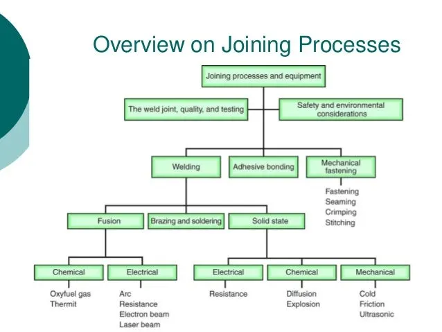
Fastening
When parts of a machine are joined in such a way that these can be disjointed or joined again easily, it is called temporary fastening. There is no harm to the machine or its parts in temporary fastening. In temporary fastening nuts, bolts, screws, lock pin, and washer are used. These things are called fasteners. The main temporary has been explained later in the article.
Press Fit
Interference fit— is the fastening of two parts that is achieved by normal force, friction and cold welding. This happens when a shaft is inserted tightly into a slightly smaller hole in another part, with the interference holding both parts in place.
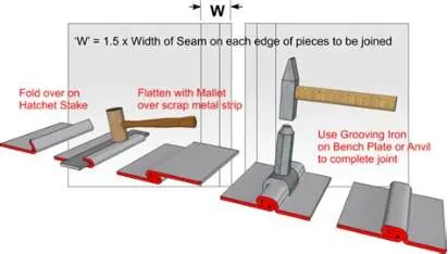
Seam joints
Joints formed by mating two separate sections of materials. They can be made or sealed in a variety of ways, including adhesive bonding, hot-air welding, solvent welding, using adhesive tapes, sealant, etc.
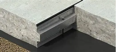
Key Joints
A key joint is a mechanism used to join a rotating machine element to a shaft. The key is then tightly fitted between the keyway and the keyseat, hence the mechanism is called a keyed joint.
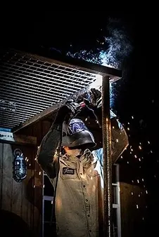
Welding
Welding is a fabrication process that joins materials, usually metals or thermoplastics, by using high heat to melt the parts together and allowing them to cool, causing fusion.
Rivet
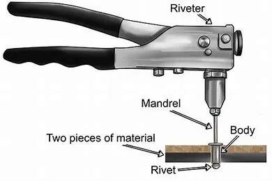
The riveted joint is a permanent joint cause rivet is a permanent mechanical fastener. A rivet is a cylindrical shaft with a head on one end and the opposite end known as a tail.
Coupling
A coupling is a mechanical device used to hold two rotating shafts together. It is a permanent joint, unlike a clutch which can be disengaged on the will of the operator. With the help of couplings, we can join two shafts which are intersecting, colinear or parallel (with a small distance). The primary purpose of couplings is to join two pieces of rotating equipment while permitting some degree of misalignment or end movement or both.
Soldering
Soldering is a process of joining two metal surfaces together using a filler metal called solder. The soldering process involves heating the surfaces to be joined and melting the solder, which is then allowed to cool and solidify, creating a strong and durable joint. 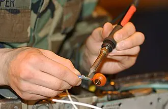
------------------------------------------------------------------------------------------------------------------------------------
------------------------------------------------------------------------------------------------------------------------------------
3) Resistance welding
It is a liquid state welding method where the metal-to-metal joint can be formed within a liquid state otherwise molten state. This is a thermoelectric method where heat can be generated at the It is a thermo-electric process in which heat is generated at the edge planes of welding plates because of electric resistance and a weld joint can be created by applying low-pressure to these plates. This type of welding uses electric resistance to generate heat. This process is very efficient with pollution free but the applications are limited because of the features like equipment cost is high, and material thickness is limited.
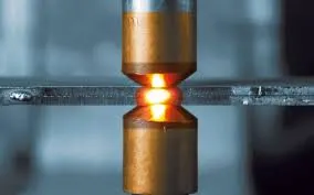
Various automotive components such as car bodies, frames, electrical wiring, fuel tanks, exhaust systems, and many more are produced using the principles of resistance welding.
Advantages include the following:
- High accuracy
- Cost-effective
- Repeatability
- Safe use due to very little smoke or fumes
- Environmental friendliness compared to other welding methods
------------------------------------------------------------------------------------------------------------------------------------
------------------------------------------------------------------------------------------------------------------------------------
4) Fusion Welding
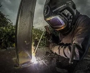
Fusion welding is a process of joining two or more materials by heating them to their melting point or above, followed by the solidification of the molten materials to form a strong, permanent bond.
The process involves the localized melting and solidification of the base material and/or filler material, with or without the application of pressure, to create the weld joint.
Types:
- Shielded Metal Arc Welding (SMAW)– Also known as stick welding, uses a coated electrode that melts and fuses the base metal.
- Gas Tungsten Arc Welding (GTAW) – Also known as Tungsten Inert Gas (TIG) welding, this process uses a non-consumable tungsten electrode to produce the arc and filler material is added manually.
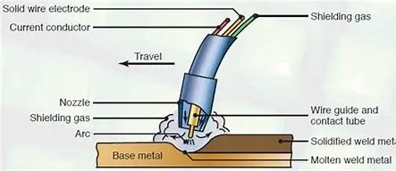
- Gas Metal Arc Welding (GMAW) – Also known as Metal Inert Gas (MIG) welding, this process uses a consumable wire electrode and a shielding gas to protect the weld from atmospheric contamination.
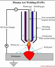
- Plasma Arc Welding (PAW) – This process is similar to GTAW but uses a more concentrated plasma arc to achieve higher welding speeds and deeper weld penetration.
- Submerged Arc Welding (SAW) – This process uses a continuous, consumable wire electrode and a granular flux to shield the weld from the atmosphere, which allows for high welding speeds and deep penetration.
- Electron Beam Welding (EBW) – This process uses a highly concentrated beam of electrons to generate heat and melt the materials to be joined. EBW is typically used for precision welding applications.
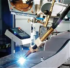
- Laser Beam Welding (LBW) – This process uses a highly focused laser beam to generate heat and melt the materials to be joined. LBW is commonly used in the automotive and aerospace industries for high-speed, automated welding.
------------------------------------------------------------------------------------------------------------------------------------
------------------------------------------------------------------------------------------------------------------------------------
5) 3-2-1 principle
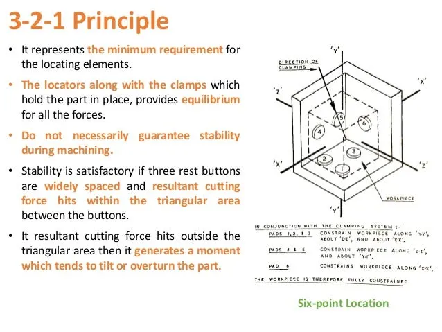
A work-piece free in space can move in an infinite number of direction. For analysis, this motion can be broken down into 12 directional movements or "degrees of freedom". All 12 degrees of freedom must be restricted to ensure proper referencing of a work-piece.
LOCATING POINTS: Locating the work is a prime necessity and requires suitable facilities. The correct setup ensures smooth insertion of a workpiece in the proper position and removing a workpiece from a jig without operational hassles or time consumption. The workpiece position needs to be precise with the guiding tool in the jig or setup pieces in the fixture.
FOOLPROOF: A foolproof design of jigs and fixtures does not permit a tool or workpiece to be placed in any other way other than the intended one.
REDUCTION OF IDLE TIME: Jigs and Fixtures must be designed in such a way that ensures smooth loading, clamping, machining, and unloading of a
WEIGHT OF JIGS AND FIXTURES: A jig and fixture must be compact, easy to handle, and low cost regarding the number of materials used without giving up stiffness and rigidity.
JIGS PROVIDED WITH FEET: Some jigs require feet so that they can be placed on the table firmly.
MATERIALS FOR JIGS AND FIXTURES: Jigs and Fixtures are usually created with hardened materials to resist wear & tear and avoid frequent damage—for example, Mild steel, Cast iron, Die steel, High-speed steel, Caesium.
CLAMPING DEVICE: A suitable clamp is rated for its strength. It should be able to hold a workpiece firmly in its position while bearing the strain of the cutting tool simultaneously, without springing.
------------------------------------------------------------------------------------------------------------------------------------
------------------------------------------------------------------------------------------------------------------------------------
6)Body coordinate system
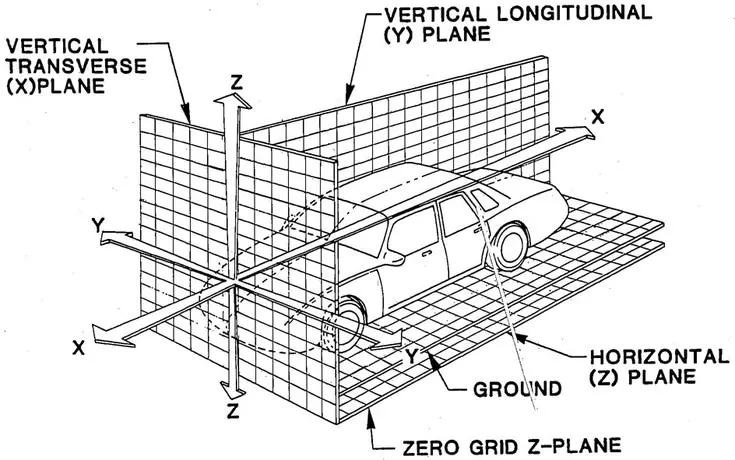
The coordinate system is orientation in terms of x, y and z relative to the vehicle, as in which axis goes in which direction; normally defined as {x, y, z} in terms of the directions of the vehicle.
Automotive sheet metal components are designed in CAD (Computer aided Design) software e.g. CATIAv4-v5, UG, ProE, Ideas, In any cad tool, there is a default axis system X, Y, Z.
- All vehicle product drawings are identified numerically relative to three vehicle planes described and shown below.
- X= longitudinal direction (fore & after-F/A) or (Front O line-FOL). Y= transverse direction (Cross car-C/C) or (Centre O line-COL).
- Z= Vertical direction (Up & down- U/D) or (Bottom O Line-BOL).
- The origin of the body coordinate system (OX) is defined at the front centre of a vehicle. It indicates a length of car & the coordinate system (OZ) is below its underbody indicates height of car & the coordinate system (OY) its starting point is the centre of car body indicates width of car.
------------------------------------------------------------------------------------------------------------------------------------
------------------------------------------------------------------------------------------------------------------------------------
7) BODY PLANE SYSTEM:
- Body planes are the reference plane in an automotive car. These planes are used to define the GD & T of all car parts in a automotive domain.
- Body planes are three mutually perpendicular imaginary planes. These are generally considered to be present at the driver position or sometimes at the engine location or at the front end of the car depending on the customer.
- The measurements from the body planes to the parts are called as body line dimension.
These body planes are called as
- FOL Front “O” line.
- COL Centre “O” line
- BOL Body “O’ line
- The measurement along FOL or X-axis is called as F/A Frontaft.
- The measurement along COL or Y-axis is called as C/C Cross car.
- The measurement along BOL or Z-axis is called as U/DUP down.
Bodyline dimensions are essential for the reasons stated below,
- It defines the exact position of each product in the vehicle w.r.t. a fixed origin.
- It ensures flawless design for assembly.
- While designing lines, all the designs are carried out relative to the bodyline, viz, fixture, turn table etc.
- It assists in easy location of different parts in a vehicle.
- It aims in creating a standardized system.
- It assists in quality checks.
These are basic essential thing that body line dimension would help in BIW. It could help in designing lines like welding lines, assembly lines or car body through fixture & turntable etc. This help in designing every tools. Particular assembly or parts are designed w.r.t body lines or an axis system or car line also helps in quality while doing CMM of that system. CMM is basically done with the help of coordinate. It has relate particular fixture with that car part, because that dimension, coordinates of hole & pin should match so it will help in quality check also. We just give co-ordinates that belong to that hole both coordinate should match. With this matching means quality is approved. Below figure shows some example.