Week 2:- BiW Fixture Basics Challenge
1. What is the process of project execution activity
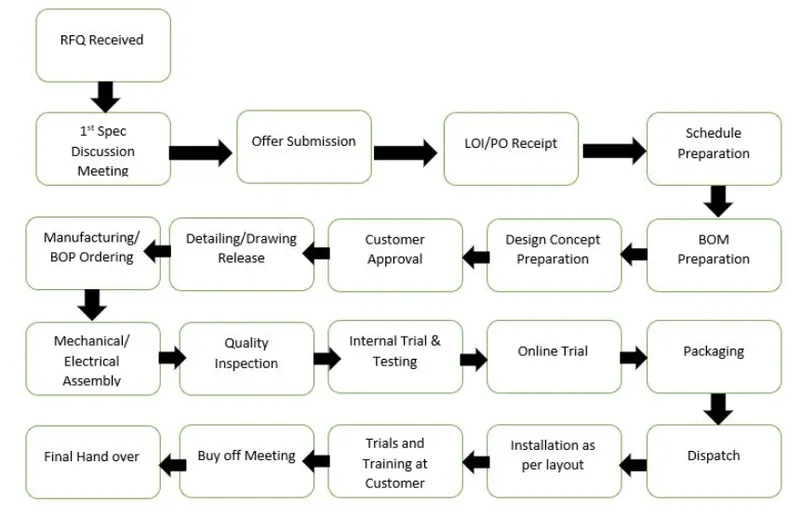
RFQ Received-
RFQ means Request for quotation, where the customer gives us a requirement, specifications, etc.
in this customer provide technical offer , commertial offer, expected timeline of the project, and other details in the form of documents.
1st Spec Discussion Meeting-
After recieving of quotation the inhouse meeting is carried out for the specifications requirement, the detailed discusion takes place on the project from its designing to manufacturng.
the time line is discuss also the customer is capable to provide that much service or not that is also decided for better timeline.
after that the deals with customer for minimum cost and better quality as they can provide.
Offer Submission-
Finalized result from 1st two step is taking through legel documents and send to customer for approval.
LOI/PO Received-
The PO means Purchase Order is release after sanctioning the quotation.
This is the main stage where we are giving the order to customer to start the work.
Schedule Preparation-
After releasing the PO the schedule or the project is devided into small times of work with deadlines.
that is discuss with customer and schesule is share to them for timely output.
by considering the deadline of project the work is handling simultaniously from customer end also.
BOM Preparation-
Bill Of Material is the detail list of parts or components which is require to manufactre the final product.
BOM contains type of material, quantity of parts, technical specification of documents etc
Design Concept Preparation-
Base on the customer requirement and the technical specification the design is prepared and discuss with customer.
Customer approval-
The created design is share with customer for their approval and satifaction with design.
once the design is finalised then it is going to CAE team also for analysis.
Drawing Release-
After the 3D design is finalized then the drawings are released for manufacturing.
Manufaturing-
Based on drawings and 3D data the manufacturing is geting started.
it can be CNC, VMC or Casting, Moulding etc
Mechanical Assembly-
This is the stage where some production asthetics are consider.
that how parts is going to assemble each other its having some fits and tolerances for assembly.
the assembly chart is prepared for operators for ease of understanding.
Quality-
The quality department is simulteniously checking the components, production process, mechanical assemblies for defects and preparing quality documents for approval.
Trials-
The internal trials and testing is carried out for checking feasibility of the product.
Packaging-
After the all manufaturing, quality, and testing is done the final product is getting to ready for dispatch to customer.
The packaging is done by considring type of product, way of transportation, time required for it, etc.
The product is not effect any damage by handling, transportation.
Installation-
The installation is done according to layout prepared it considerd space required for installation.
The layout is consider according to functionality, application, process sequence.
Trial and training to customer-
Trial is perform after installation is done. during trial the provision of training is also carried out simulteniously.
during training the saftey od operator is consider, the production per hour is discuss, the operating methods is discuss.
Buy Off Meeting-
In this meeting we are clearing some doubts of customer and we are providing some additional information to customer.
At the end of meeting all the doubt and the detailed are provide to customer to satisfaction of customer and hep to procced furher with the product.
Also we are telling to be available in case of any help or emergencies for some period of time.
Final Hand Over-
In this step the product and all the data and documentaion is provided to customer.
2. What are the types of joining processes-
-Joining process can be thermal or non-thermal type
-Joining include welding, brazing, soldering, adhesive bonding of material.
-They produce permanent joint between the parts to be assembled.
-They cannot be separated easily by application of forces.
-They are mainly used to assemble many parts to make a system.
A) Thermal-
1. Arc welding
2. MIG Welding
3. Laser Brazing
B) Non-thermal
1.Clinching
2. Glueing
3. Riveting
a) Brazing & Soldering- Melting of filler rod only
Brazing: higher temperature, brass filler, strong
Soldering: lower temp, tin-lead filler, weak
b) Welding - Melting of filler rod and base metal
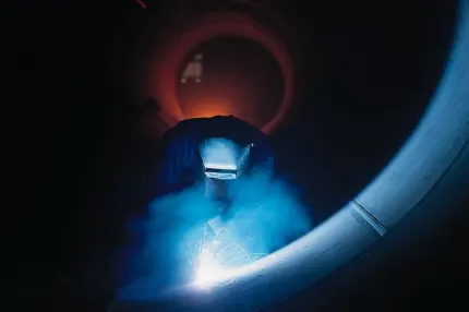
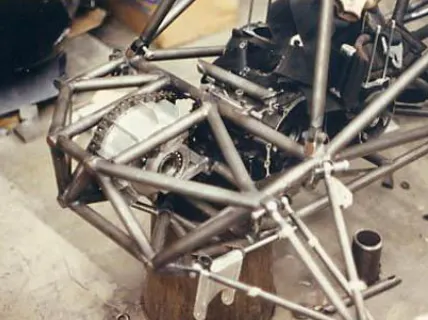
Welding processes can be broadly classified into
(i) fusion(non-pressure) welding
Arc Welding
1)Gas tungsten arc welding(TIG) or (GTAW)
2)Gas metal arc welding(MIG) or (GMAW)
3)Shielded metal arc welding(SMAW)
4)Submerged arc welding
5)Plasma arc welding
6)Flux cored arc welding(FCAW)
Resistance welding
1)Spot welding
2)seam welding
3)Projection welding
4)Resistance butt welding
Gas welding
1)Oxy-acetylene welding
2) Oxy-hydrogen welding
3)Air -acetylene welding
4)Pressure Gas welding
Thermo chemical welding Process
1)Thermit welding
2)Atomic hydrogen welding
Radient energy welding Process
1)Electron beam welding
2)Laser beam welding.
(ii) solid state welding(pressure welding)
In this method, joining is done by application of pressure only or a combination of heat and pressure.
Even if heat is used, the temperature in the process is less than the melting point of the metals being welded (unlike in fusion welding).No filler metal is utilized.
-Diffusion welding: Two part surfaces are held together under pressure at elevated temperature and the parts join by solid state diffusion.
-Friction welding/Stir welding: Joining occurs by the heat of friction and plastic deformation between two surfaces.
-Ultrasonic welding: Moderate pressure is applied between the two parts and an oscillating motion at ultrasonic frequencies is used in a direction parallel to the contacting surfaces
3. What is Resistance Welding & its application in the automotive sector-
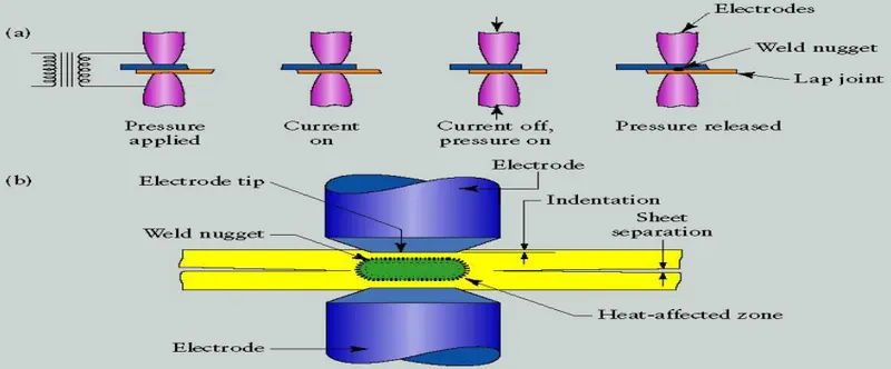
Resistance welding is the process in which two or more parts are welded by the coordinated and regulated use of heat and pressure.
-The heat in the resistance welding
process is generated by the resistance
offered by the work pieces to the flow of
low voltage high density electric current.
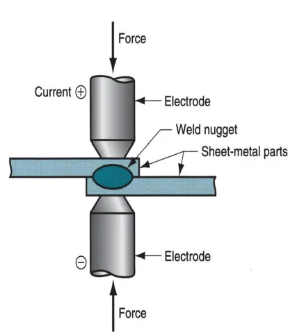
-A typical resistance welding cycle consists of
1) squeeze
2) weld
3) hold period
-The resistance welding processes include
spot welding, seam welding, roll spot welding, projection welding, upset welding, flash welding and percussion welding.
- Practically all metals can be resistance welded and the operation is quite fast.
- Weld nugget is generated by this process
- RW uses no shielding gases, flux, or filler metal.
- electrodes that conduct electrical power to the process are non-consumable
Current : 5000 to 20,000 A
Voltage : < 10V
Duration of current : 0.1 to 0.4 s (in spot-welding operation)
- Resistance in the welding circuit is the sum of
(1) resistance of the electrodes,
(2) resistances of the sheet parts,
(3) contact resistances between electrodes and sheets.
- Resistance at the welding surfaces depends on surface finish, cleanliness,
contact area, force. No paint, oil, dirt, and other contaminants should be present
to separate the contacting surfaces.
- Advantages: no filler rod required, high production rates, automation and
mechanization are possible.
- disadvantages: restricted to lap joint, costly equipment
- Application-
1. Resistance seam welding is used to join
fluid tight joint in sheet metal industries, like steel fuel tank, still cans ,steel drums domestic radiators.
2. Spot welding is used in
metal frame assemblies, Battery manufacturing and electronics, gas control components, exhaust system
4. What is fusion welding & types of fusion welding with its application in the automotive sector-
Fusion welding:
In fusion-welding processes, heat is applied to melt the base metals.
In many fusion welding processes, a filler metal is added to the molten pool during welding to facilitate the process and provide strength to the welded joint.
When no filler metal is used, that fusion welding operation is referred to as Autogenous weld.
Fusion welding joints edges of different material by heating them to melting points.
Types:
a) Arc welding
Arc welding Process
It is a fusion welding process in which the melting and joining of metals is done by the heat energy generated by the arc between the work and electrode.
an electric arc is generated when the electrode contacts the work and then quickly separated to maintain the gap.
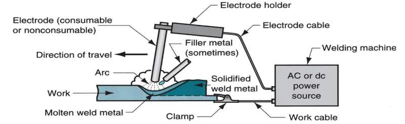
A temperature of 5500°C is generated by this arc.
This temperature is sufficient to melt most of the metals. The molten metal, consisting of base metal and filler, solidifies in the weld region.
In order to have seam weld, the power source moves along the weld line.
Two types of electrodes are used: consumable and non-consumable
A. Consumable electrodes:
Present in rod or wire form with 200 to 450 mm length and less than 10 mm diameter. This is the source of filler rod in arc welding.
The electrode is consumed by the arc during the welding process and added to the weld joint as filler metal.
The consumable electrodes will be changed periodically as it is consumed for each welding trials. This becomes a disadvantage for welder and reduces the production rate.
B. Non-Consumable electrodes:
The electrodes are not consumed during arc welding. Though this is the case, some depletion occurs because of vaporization.
Filler metal must be supplied by means of a separate wire that is fed into the weld pool.
b) Resistance welding
There is two resistance welding process-
1. Resistance spot welding:
It work by producing heat on the two electrodes. However, the bonding process depends on the properties & thickness of the materials.
The process confines the welding voltage to a single spot when fusing of different workpieces.
2. Resistance Seam Welding:
It is form of spot welding, that include a sequence of joint alternating nuggets.
It uses shifting disks to replace the spot welding electrodes to join the materials together.
c) Gas welding-
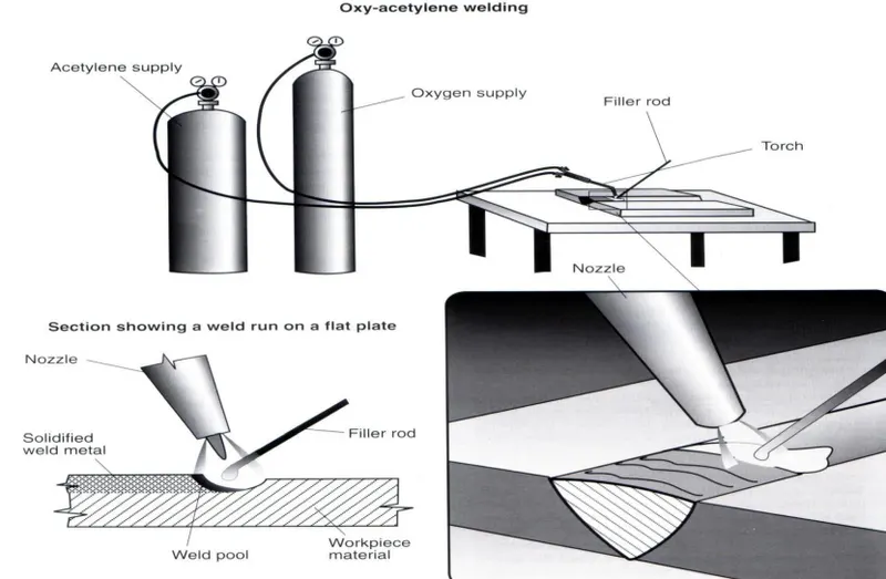
In this process, various fuels are mixed with oxygen and burnt to perform welding. Eg: Oxyacetylene welding
-Oxyacetylene welding (OAW):
In this case, welding is performed by a flame formed by the combustion of oxygen and acetylene.
The flame comes from a torch. A filler rod coated with flux is used sometimes which prevents oxidation, creating a better joint.
Acetylene is a famous fuel because it is capable of generating a temperature of 3500°C.
5. What is the 3-2-1 principle-
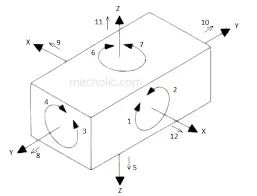
To manufacture the part having main three steps-
1. suppoerting
2. positioning
3. clamping
There is two main intensions while placing the workpiece on fixture
1. positioning the workpiece precisionaly at design coordinates
2. fixing all DOF so that the workpiece do not move from position
An extensively method for this operation is to use the 3-2-1 principle
3-2-1 principle is the workpiece holding principle which is restrict the all directional movements of the workpiece while machining to perform various operation on it.
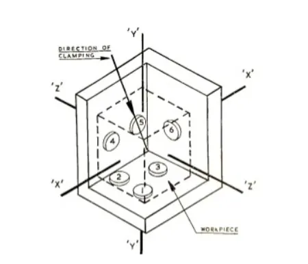
-In this consider the workpiece to fix all DOF where 3 pins are on 1st plane, 2 pins are on 2nd plane which is perpandicular to 1st plane, 1 pin on 3rd plane which is perpandicular to 1st and 2nd plane.
-By this way we are restricting total 9 DOF, where other 3 DOF is used to Loading and unloading of workpiece.
-This remaining 3 DOF is restricted by clamping method while doing operation on workpiece.
-The aim is to machine the workpiece in desiger size and shape with accuracy.
6.Define Body coordinate system
The vehicle co-ordinate system is the base co-ordinate axis for any vehicle.
the structure of the vehicle is design according to VCS (vehicle co-ordinate system)
while designing the vehicle VCS is taking generally at centre of front axle point to ease of design and assembly of vehicle.
According to VCS all othe WCS (work co-ordinate system) is taken for other parts to design.
The VCS are fixed in reference frame attached to vehicle.
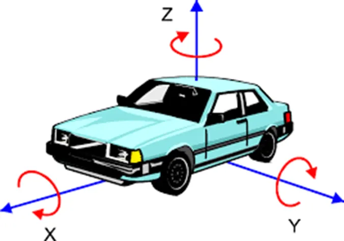
In this X, Y, Z axis are there,
Where,
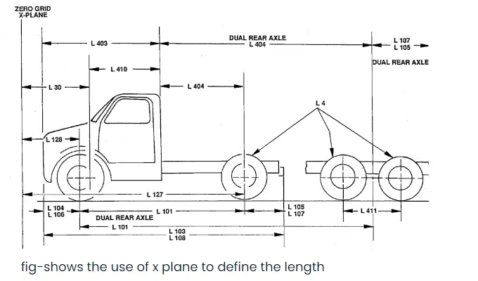
X represent- Length of vehicle
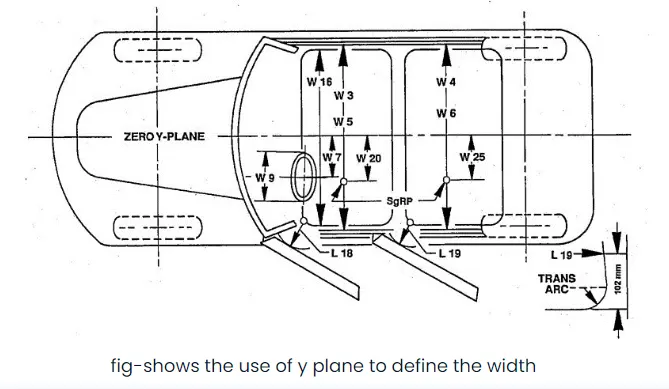
Y represent- Width of vehicle
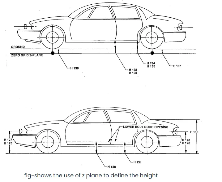
Z represent- Height of vehicle
7. Elaborate Body plane system & its essentials
Body plane are three imaginary perpandicular plane. this are imaginary reference plane of any vehicle that is used for GD&T references of copmonents and assemblies.
that measurement of parts or componets from reference plane are called bodyplane dimensions.
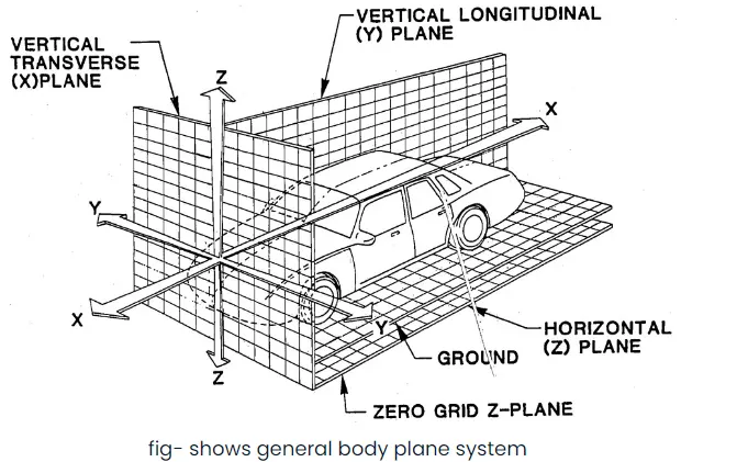
Bodyline dimensions required for below reason
1. this defines position of each part or product with respect to origin.
2. this is ensure the flowless design of vehicle for assemblies.
3. while designing lines, all the design are carried out relative to the bodylines viz.fixtures, Turntables etc.
4. it can guide for easy locating of different parts and products.
5. this aims to create the std. procedure for designing vehicle.
6. this assist the quality check.
some example are shows below-