Week 2:- BiW Fixture Basics Challenge
1. Process involved in project execution activity:
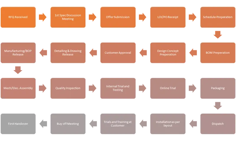
RFQ’s Received
RFQ stands for Request for Quotation. It is a formal document or process used by organizations to solicit price quotes or bids from potential suppliers or vendors for specific products or services. The RFQ is typically used when the organization already has a clear understanding of its requirements and seeks competitive pricing from multiple suppliers before making a purchasing decision.
1st Spec Discussion Meeting:
This refers to a meeting or discussion where the specifications of a product or component are discussed in detail. It may involve stakeholders such as designers, engineers, manufacturers, and clients or customers to ensure clarity and alignment on the required specifications.
Offer Submission:
Offer Submission refers to the process of submitting a formal proposal or bid to a prospective client or customer in response to a specific request or opportunity. It is a crucial step in business transactions and procurement processes.
LOI/PO Receipt
A Letter of Intent is a document that outlines the preliminary agreement or understanding between two parties before a formal contract is established.
A Purchase Order (PO) Receipt is a document that serves as proof of delivery and receipt of goods or services as per a purchase order.
Schedule Preparation
Schedule Preparation refers to the process of creating a schedule or timeline for a project or set of activities. It involves identifying the tasks, determining their sequence, estimating their duration, and assigning resources to ensure the project is completed within the desired timeframe
BOM Preparation
BOM Preparation refers to the process of creating a Bill of Materials (BOM) for a product. A BOM is a comprehensive list of all the components, parts, materials, and sub-assemblies required to manufacture or assemble a product.
Design Concept Preparation
Design Concept Preparation refers to the initial stage of the design process where ideas and concepts are generated and developed for a product, system, or project. It involves gathering information, brainstorming, and creating preliminary design concepts to guide the subsequent design phases.
Customer Approval
Customer Approval refers to the process of obtaining formal authorization or acceptance from the customer or client for a product, service, design, or proposal. It is a critical step in the business process, as it signifies that the customer is satisfied with the deliverables and agrees to proceed with the next steps.
Detailing and Drawing Release
Detailing and Drawing Release refers to the stage in the design and manufacturing process when detailed engineering drawings and specifications are finalized and released for production or construction. It involves creating comprehensive technical drawings that provide all the necessary information for manufacturing, assembly, or construction of a product or structure.
BOP Release
The BOP Release is the official authorization to begin production based on the approved BOP or BOM.
It is typically issued by the manufacturing or production management team after reviewing and verifying the accuracy and completeness of the BOP/BOM.
The BOP Release ensures that all the necessary components, materials, and instructions are available and ready for production.
Mechanical/Electrical Assembly
Mechanical and Electrical Assembly refers to the process of assembling various mechanical and electrical components to create a functional product or system. It involves the integration of different parts, subassemblies, and electrical components to ensure proper functioning and performance.
Quality Inspection
Quality Inspection refers to the process of evaluating and verifying the quality of products, components, or processes to ensure they meet predetermined standards and specifications. It is a critical step in the manufacturing or production process to identify any defects, non-conformities, or deviations from the desired quality requirements.
Internal Trial & Testing
Internal trial and testing refer to the process of conducting trials and tests within an organization or company to evaluate the performance, functionality, and quality of a product or system before its final release or deployment. It involves assessing the product or system's capabilities, identifying any issues or deficiencies, and making necessary improvements or refinements.
Online Trial
Online trial refers to the testing and evaluation of the fixture's performance and functionality in an online or operational environment. This type of trial is conducted with the actual production line or manufacturing process to validate the fixture's effectiveness in holding and positioning the body structure during assembly.
Packaging
Packaging refers to the process of securely and safely packaging the fixture for transportation, storage, and delivery to the customer or end-user. Proper packaging is essential to protect the fixture from damage during handling and shipping.
Dispatch
Dispatch fixture refers to the process of sending or delivering the fixture to its intended destination, such as the customer's facility or a production site. The dispatch process involves several steps to ensure the fixture reaches its destination safely and on time.
Installation as per layout
Installation as per the layout refers to the process of setting up and positioning the fixture according to the predetermined layout or design specifications. Proper installation is crucial to ensure the fixture functions effectively and supports the assembly process accurately.
Trials & Training at Customer
Trials and training at the customer's site are important steps in the implementation of a BIW (Body-in-White) fixture. These activities help ensure that the fixture functions optimally and that the customer's personnel are proficient in operating and maintaining the fixture.
Buy Off Meeting
A buy-off meeting is a crucial step in the completion of a project or the delivery of a product or service. It is a formal meeting between the customer and the supplier or vendor to review and assess the deliverables against the agreed-upon requirements and specifications. The purpose of the buy-off meeting is to verify that the project or product meets the customer's expectations and is ready for acceptance and payment.
Final Handover
Final handover refers to the process of formally transferring a completed project or deliverable to the client or customer. It signifies the completion of the work and the transfer of responsibility and ownership to the client.
2. Joining Process:
A joining process refers to a manufacturing operation or technique used to connect or combine two or more materials to form a single, unified structure. The purpose of a joining process is to create a strong and durable bond between the materials, allowing them to function together as a cohesive unit. Joining processes are commonly employed in various industries, including manufacturing, construction, automotive, aerospace, and more.
Types of Joining Process
- Metallurgical Joining
- Mechanical Joining
- Chemical Joining
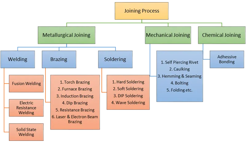
Metallurgical Joining
Welding
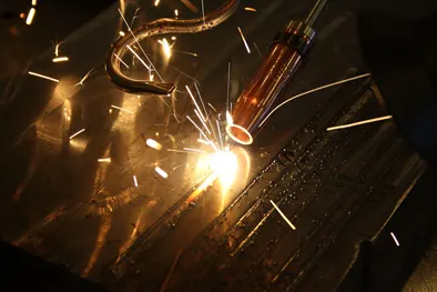
Welding is a process of joining two or more pieces of metal together by melting the materials and allowing them to cool and fuse. It is a commonly used technique in manufacturing, construction, and various other industries. Welding is essential for creating strong and durable connections between metal parts.
During the welding process, a heat source, such as an electric arc or a gas flame, is used to melt the edges or surfaces of the materials being joined. The molten metal then solidifies, creating a bond that fuses the pieces together. In some cases, a filler material, which is compatible with the base metals, is used to enhance the strength of the joint.
Brazing
Brazing is a joining process similar to welding, but it uses a different principle. It involves joining two or more metal pieces by melting and flowing a filler metal, called brazing alloy or brazing filler metal, into the joint. The filler metal has a lower melting point than the base metals being joined, typically above 450°C (840°F) but below the melting point of the base metals.
The brazing process begins by thoroughly cleaning the surfaces of the metal parts to be joined. This helps ensure a strong bond by removing any oxides, dirt, or other contaminants. The parts are then heated to a temperature slightly above the melting point of the filler metal but below the melting point of the base metals.
Once the proper temperature is reached, the filler metal is introduced to the joint area. It is usually in the form of a wire, rod, or pre-placed paste. The heat from the base metals causes the filler metal to melt and flow into the joint by capillary action. As the joint cools, the filler metal solidifies, creating a strong bond between the base metals.
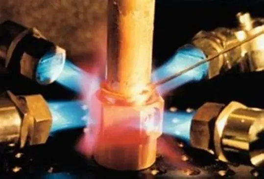
Brazing finds applications in various industries, including automotive, aerospace, electronics, plumbing, and jewelry manufacturing. It is commonly used to create heat exchangers, electrical contacts, tubing assemblies, tooling, and decorative metalwork.
Soldering
Soldering is a process of joining two or more metal pieces together using a filler metal called solder. Unlike welding and brazing, soldering does not involve melting the base metals but rather melting the solder itself. The solder typically consists of a mixture of tin and lead or other alloys, with a lower melting point than the base metals.
The soldering process begins by cleaning the surfaces of the metal parts to be joined, similar to brazing. Flux, a chemical compound, is often applied to the cleaned surfaces to prevent oxidation and promote wetting and flow of the solder. Flux also helps remove any existing oxides from the metal surfaces.
The next step is heating the joint area using a soldering iron or a soldering gun. These tools provide the necessary heat to melt the solder. The heat is applied directly to the joint while the solder is introduced to the heated area. Once the solder melts, it flows into the joint by capillary action and forms a bond between the metal pieces.
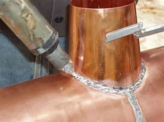
Overall, soldering is a widely used technique for creating electrical connections, assembling electronic components, and joining small metal parts. It offers a reliable and cost-effective method for many applications that do not require the high strength or elevated temperatures provided by welding or brazing.
Mechanical Joining
Mechanical joining refers to the process of joining two or more components together without the use of heat or additional materials such as solder or filler metals. It involves the use of mechanical forces, fasteners, or interlocking mechanisms to create a secure and durable connection between the parts.
Self-Piercing Rivet (SPR)
A self-piercing rivet (SPR) is a specialized fastening method used to join two or more materials together, particularly in automotive and aerospace industries. It is designed for applications where traditional riveting or welding techniques may not be suitable or feasible.
The self-piercing rivet process involves inserting a specially designed rivet into pre-drilled or pre-punched holes in the materials to be joined. Unlike conventional rivets, self-piercing rivets do not require a pre-drilled hole in the bottom material. Instead, they pierce through the top material while forming a mechanically secure joint.

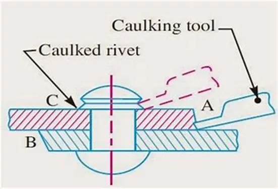
Caulking
Caulking refers to the process of sealing gaps, joints, or seams between materials using a pliable material called caulk. It is commonly used in construction, woodworking, and other applications to create a watertight, airtight, or weather-resistant seal.
Caulk is typically a flexible compound made from various materials such as silicone, latex, or polyurethane. It comes in different forms, including cartridges that are applied with a caulking gun or squeeze tubes for manual application.
Hemming
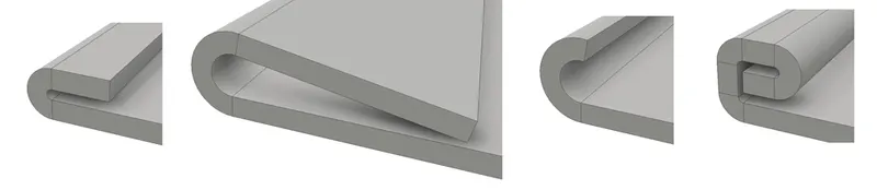
Hemming refers to the folding and stitching or folding and bonding of fabric or material to create a neat and finished edge. It is commonly used in clothing, curtains, tablecloths, and other fabric-based products. Hemming prevents the material from unraveling, adds strength to the edge, and enhances the overall appearance. There are different hemming techniques, including single-fold hems, double-fold hems, blind hems, and rolled hems. The choice of hemming method depends on the material, desired appearance, and functionality.
Sealing
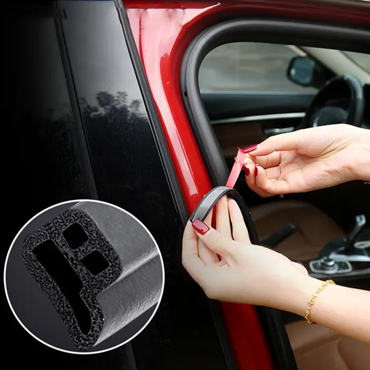
Sealing involves closing or joining two or more surfaces together to create a barrier or containment. It is used in various applications, such as packaging, plumbing, electronics, and automotive industries. The purpose of sealing can be to prevent leakage, protect against environmental factors like dust or moisture, or provide airtight or watertight properties. Sealing methods can include adhesive bonding, welding, soldering, or using gaskets and seals. The specific sealing technique depends on the materials being joined, the desired strength and durability, and the environmental conditions the seal must withstand.
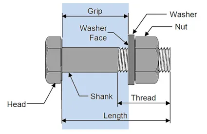
Bolting
Bolting is a method of joining two or more components together using bolts. Bolts are threaded fasteners with a head at one end and a threaded portion at the other. They are used in conjunction with nuts to create a secure and removable connection between parts.
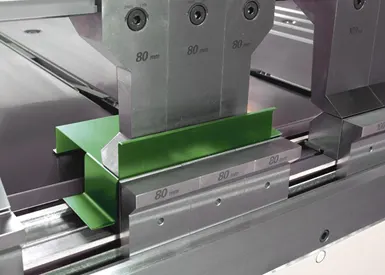
Folding
Folding is a process of bending or creasing a material, typically a sheet or a piece of fabric, to create folds or creases along specific lines. It is a common technique used in various industries, crafts, and everyday tasks.
When folding materials, it's essential to consider factors such as the material's flexibility, the required accuracy of the fold, and the overall design or purpose of the folded object. Proper measurements, alignment, and technique are crucial to achieve the desired results.
Chemical Joining
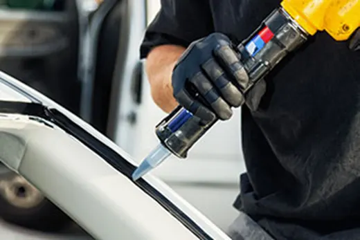
Chemical joining refers to the process of joining two or more components together by using chemical reactions or bonding agents. Unlike mechanical joining, chemical joining relies on the interaction between the materials at a molecular level to create a strong and permanent bond. Various methods of chemical joining exist, including adhesive bonding
It's important to note that proper surface preparation, material compatibility, and curing processes are crucial for achieving reliable and durable chemical bonds. The performance of chemical joints can be affected by factors such as temperature, humidity, chemical exposure, and mechanical loads. Therefore, careful consideration of these factors is necessary for the successful application of chemical joining methods.
3. Resistance Welding & its application in the automotive sector
Resistance Welding
Resistance welding is a type of welding process that uses the application of electric current and pressure to join metal components together. It is commonly used for welding materials such as steel, stainless steel, and aluminum. In resistance welding, the heat required for joining is generated by the resistance to electric current flow at the interface of the joint.
There are several different forms of resistance welding (e.g. spot and seam, projection, flash, and upset welding) which differ primarily by the types and shapes of weld electrodes that are used to apply the pressure and conduct the current. The electrodes, typically manufactured from copper based alloys due to superior conductive properties, are cooled by water flowing through cavities inside the electrode and the other conductive tooling of the resistance welding machine.
Resistance welding offers several advantages, including fast welding speeds, high production rates, good joint strength, and minimal distortion. It is widely used in industries such as automotive, aerospace, appliance manufacturing, and construction for various applications.
Spot Welding
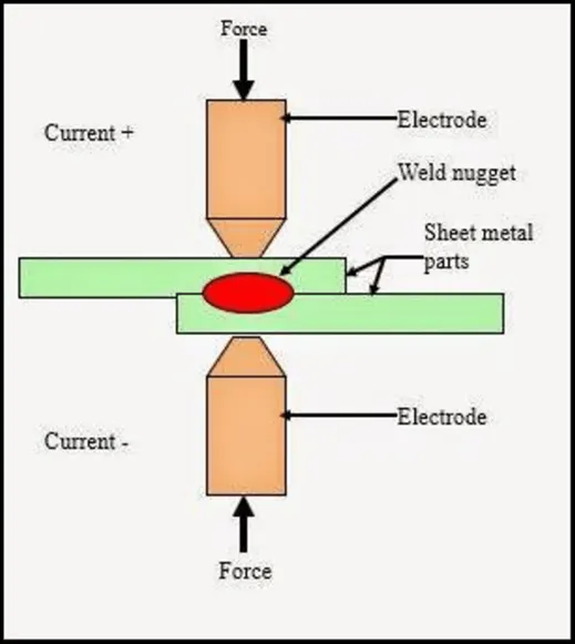
Spot welding is the most common form of resistance welding. It involves the application of current and pressure at discrete points on the joint, creating small fusion spots.
Spot welding is extensively used in BIW manufacturing to join thin sheet metal components together. It is used for creating welds at discrete points, such as joining two or more sheet metal panels. Spot welding provides high joint strength and is suitable for high-volume production.
BIW Spot Welding
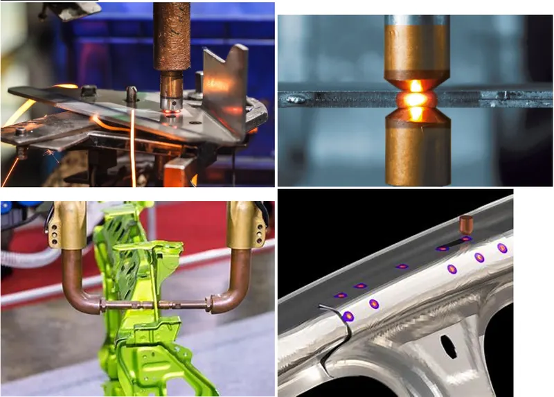
Spot welding is commonly used for applications where a strong and reliable joint is required, such as automotive body panels, appliances, sheet metal fabrication, and electrical components.
Seam Welding
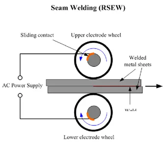
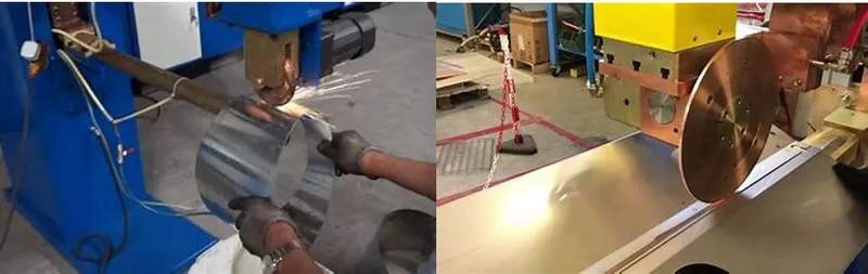
Seam welding is a welding process that involves joining two metal sheets or plates along a continuous seam. It is a variation of resistance welding and is commonly used for the production of longitudinal welds in cylindrical or rectangular-shaped components, such as pipes, tubes, tanks, and automotive body panels.
In seam welding, the two metal surfaces to be joined are placed in close contact and clamped between two electrodes. The electrodes conduct an electric current through the metal, generating heat at the interface. As the heat is applied, the metal surfaces melt and fuse together, forming a continuous weld along the seam.
Types of Seam Welding
- Resistance Seam Welding
- Laser Seam Welding
Advantages of Seam Welding
- High production rates: Seam welding is a continuous process, allowing for high-speed and efficient production.
- Strong and leak-proof joints: The continuous weld along the seam provides a strong and leak-proof connection.
- Automation capability: Seam welding can be easily automated using robotic systems, ensuring consistent and precise welds.
- Versatility: Seam welding can be performed on various metal types, including steel, stainless steel, aluminum, and others.
However, seam welding also has some limitations, such as limited joint configurations and the need for precise alignment of the metal surfaces. It is primarily used for applications where a continuous and uniform weld along a linear seam is required.
Projection Welding
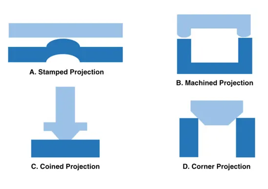
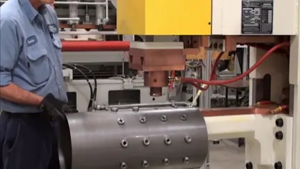
In Projection welding size and shape of individual welds are determined by the presence of projections, embossments or intersections on the metals to be joined.
Metals are heated and coalescence is achieved not through the use of an arc, but through the metals resistance of electrical currents passing through them as they are held together with pressure by electrodes.
In projection welding the pieces to be joined are clamped between two electrodes under force, an electrical current sent through them.
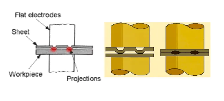
Projection welding is commonly used for applications where multiple spot welds or specific joint configurations are required. It is suitable for joining various metals, including carbon steel, stainless steel, and aluminum. The process is versatile and can accommodate a wide range of component sizes and geometries.
Types of Projection Welding
Flash Welding
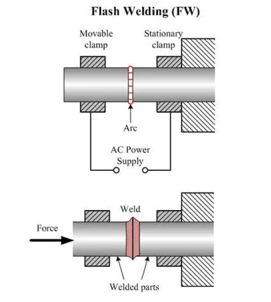
In flash welding, the two metal components to be joined are clamped together between two electrodes. When an electric current is passed through the electrodes, a high-intensity arc is generated at the interface between the components. The heat produced by the arc melts and fuses the metal surfaces, creating a weld joint. The welding process is completed in a fraction of a second, hence the name "flash" welding.
Flash welding advantages:
Strong and reliable joints: Flash welding produces high-quality welds with excellent strength and integrity.
Speed and efficiency: The welding process is fast, allowing for high production rates and cost-effective manufacturing.
Versatility: Flash welding can be used to join a wide range of metals, including carbon steel, stainless steel, aluminum, and copper alloys.
Material savings: Flash welding requires minimal additional materials or consumables, reducing waste and costs.
However, flash welding also has some limitations, such as limited joint configurations and the need for precise alignment of the metal components. It is primarily used for applications where a quick and robust weld joint is required, particularly for large-scale production.
Upset Welding
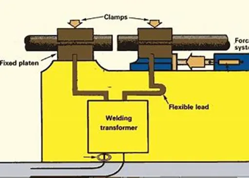
In upset welding, the two metal components to be joined are aligned and held together between two electrodes. An electric current is passed through the electrodes, generating heat at the interface between the components. The heat causes the metal to soften and deform, and pressure is applied to forge the softened metal together. The welding process typically occurs within a few milliseconds, creating a solid-state bond.
Upset welding advantages:
Strong and durable joints: Upset welding produces welds with high strength and integrity, as the metal components are forged together without the need for additional materials.
Efficiency and speed: The welding process is fast, allowing for high production rates and cost-effective manufacturing.
Versatility: Upset welding can be used to join a variety of metals, including steel, aluminum, and copper alloys.
Minimal distortion and heat-affected zone: Since upset welding is a solid-state joining process, it minimizes distortion and reduces the heat-affected zone compared to other welding methods.
Applications
Upset welding is commonly used for joining wires, rods, tubes, and other cylindrical components. It is particularly suitable for applications where a continuous and uninterrupted joint is desired.
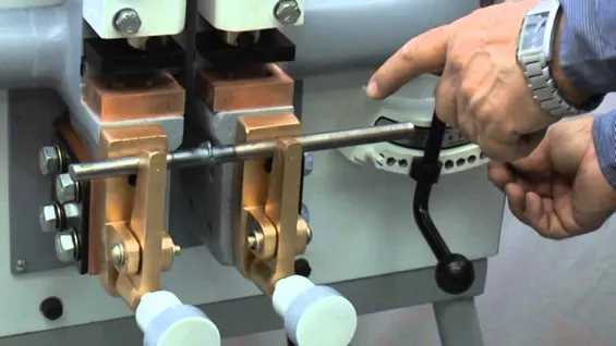
4. Fusion welding & types of fusion welding with its application in the automotive sector
Fusion welding is a type of joining process in which two or more work pieces are melted and fused together to form a strong joint. It involves the application of heat to raise the temperature of the work pieces above their melting point, allowing the molten material to mix and solidify, creating a metallurgical bond.
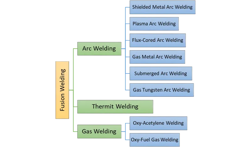
Arc Welding
Shielded Metal Arc Welding
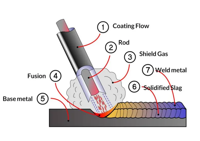
Shielded Metal Arc Welding (SMAW), also known as manual metal arc welding or stick welding, is a welding process that uses a consumable electrode coated with flux to join metals.
Advantages of Shielded Metal Arc Welding:
Versatility: SMAW can be used to weld a wide range of materials, including carbon steel, stainless steel, cast iron, and non-ferrous metals.
Portability: SMAW equipment is relatively compact and portable, making it suitable for on-site welding and repairs in various industries.
Cost-effectiveness: SMAW is generally a cost-effective welding process, as it requires simple equipment and does not rely on expensive shielding gases.
Outdoor applicability: SMAW can be performed in outdoor environments, as the flux coating on the electrode provides the necessary shielding from atmospheric contamination.
Good penetration: SMAW produces deep penetration in the welded joint, resulting in strong and reliable welds.
Disadvantages of Shielded Metal Arc Welding:
Low welding speed: SMAW is typically slower compared to other welding processes, which can lead to longer welding times and increased labor costs.
Manual operation: SMAW requires skilled welders who can manually control the arc length, electrode angle, and travel speed, making it more operator-dependent.
Slag removal: After each weld pass, the slag created by the flux coating must be chipped off, which adds to the post-welding cleanup time.
Limited positional welding: SMAW is more challenging to perform in certain positions, such as overhead or vertical-up welding, compared to other welding processes.
Limited thickness range: SMAW is better suited for medium to thick material thicknesses, and may not be as efficient for thin sheet metal welding.
Applications of Shielded Metal Arc Welding:
Construction industry: SMAW is widely used in construction projects for welding structural steel, bridges, buildings, and pipelines.
Maintenance and repair: SMAW is commonly employed for repairing machinery, equipment, and structures in industries such as manufacturing, mining, and transportation.
Shipbuilding: SMAW is used in the construction of ships and offshore structures due to its versatility and ability to weld thick steel plates.
Pipeline construction: SMAW is utilized for welding pipes, especially in remote or inaccessible areas where other welding processes may not be feasible.
Automotive and fabrication: SMAW is employed in automotive manufacturing and fabrication workshops for various welding applications.
The specific application and suitability of SMAW may vary based on the material, thickness, and welding requirements.
Plasma Arc Welding
Plasma Arc Welding (PAW) is an advanced welding process that utilizes a highly concentrated and ionized gas plasma arc to join metal components. The plasma arc is formed by passing a high-velocity gas through a constricted orifice and then ionizing it with the help of a high-frequency electric arc.
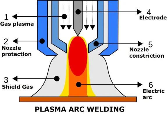
Advantages of Plasma Arc Welding:
Precise Control: PAW allows for precise control over the welding parameters, including arc current, arc voltage, gas flow, and torch movement speed. This results in highly accurate and consistent welds.
High Quality Welds: The concentrated plasma arc provides deep penetration and narrow weld profiles, resulting in high-quality welds with minimal distortion.
Versatility: PAW can be used to weld a wide range of materials, including stainless steel, aluminum, titanium, copper alloys, and other exotic metals. It is suitable for both thick and thin materials.
Welding Speed: The concentrated plasma arc enables faster welding speeds compared to other welding processes, leading to increased productivity.
Less Heat Input: PAW produces a small heat-affected zone (HAZ) due to its concentrated heat source, minimizing the risk of distortion, warping, and material damage.
No Filler Material Required: In some cases, PAW can be used for autogenous welding, where no filler material is required. This is advantageous for applications where the use of filler metal is undesirable.
Disadvantages of Plasma Arc Welding:
Equipment Cost: PAW equipment is more complex and expensive compared to traditional welding equipment, which can be a barrier to entry for some users.
Skilled Operator Required: Proper setup and operation of PAW equipment require specialized training and skills. It may take time for operators to become proficient in the process.
Limited Accessibility: The size and shape of the welding torch can restrict access to certain joint configurations and positions, making it challenging to weld in confined spaces.
Applications of Plasma Arc Welding:
Aerospace and Aircraft Industry: PAW is commonly used for welding aircraft components, such as engine parts, turbine blades, fuel tanks, and structural elements. The process's high-quality welds and ability to handle various materials make it suitable for critical aerospace applications.
Power Generation: PAW is utilized in the fabrication of power generation equipment, including gas turbines, steam turbines, and nuclear power plant components.
Automotive Industry: PAW is employed in the automotive sector for applications such as welding exhaust systems, engine components, and high-strength steel assemblies.
Petrochemical Industry: PAW is used to weld pipes, vessels, and other components in the petrochemical industry, where high-quality and reliable welds are crucial for safety and performance.
Medical and Pharmaceutical Equipment: PAW is employed in the manufacturing of medical devices, surgical instruments, and pharmaceutical equipment, where precision and cleanliness are vital.
Precision Fabrication: PAW finds applications in precision fabrication industries such as electronics, semiconductor manufacturing, and precision machinery, where high-precision welding is required.
Overall, Plasma Arc Welding is a versatile process that offers several advantages for various industrial applications. Its ability to produce high-quality welds, precise control, and versatility make it a preferred choice for many demanding welding applications.
Flux-Cored Arc Welding
Flux-Cored Arc Welding (FCAW) is a welding process that uses a tubular electrode filled with flux to join metals. The electrode consists of a hollow metal wire with a flux core inside. When the electrode is energized, an arc is formed between the electrode and the work piece, melting the metal and creating a weld joint.
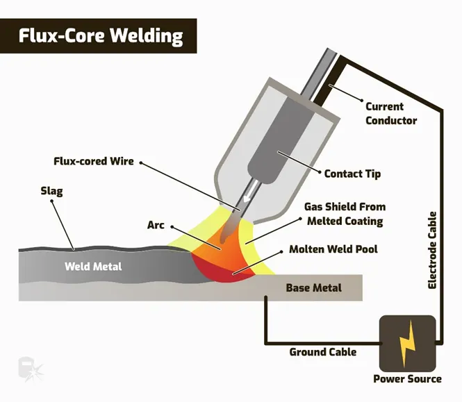
Advantages of Flux-Cored Arc Welding:
High Deposition Rates: FCAW provides high welding deposition rates, allowing for faster welding compared to some other processes. This results in increased productivity and reduced labor costs.
All-Position Welding: FCAW can be performed in all positions, including flat, horizontal, vertical, and overhead. This flexibility makes it suitable for welding in various orientations and challenging positions.
Increased Penetration: FCAW provides deeper penetration than some other welding processes, making it suitable for welding thicker materials or achieving strong welds in joint configurations with limited access.
Versatility: FCAW can be used to weld a wide range of materials, including carbon steel, stainless steel, low-alloy steel, and some non-ferrous metals. Different types of flux-cored wires are available to match the specific requirements of the base metal.
Shielding from Atmospheric Contamination: The flux core in the electrode produces a shielding gas when heated, which protects the weld pool from atmospheric contamination, such as oxygen and nitrogen. This results in cleaner and stronger welds.
Cost-Effective: FCAW is generally considered a cost-effective welding process. The use of flux-cored wires eliminates the need for external shielding gas, reducing overall welding costs.
Disadvantages of Flux-Cored Arc Welding:
Environmental Considerations: FCAW produces fumes and gases during the welding process, requiring proper ventilation and adequate personal protective equipment (PPE) to ensure the safety of the welder and others in the vicinity.
Slag Removal: Flux-cored electrodes often leave behind slag after welding, which needs to be removed after each pass. Slag removal can add to the post-welding cleanup time and effort.
Equipment Sensitivity: FCAW requires proper equipment setup and adjustment to ensure optimal welding performance. The process is sensitive to factors such as wire feed speed, voltage, and travel speed, which may require fine-tuning during welding.
Limited Thin Sheet Welding: FCAW may not be suitable for welding very thin sheet metals, as it can result in excessive heat input and potential distortion or burn-through.
Applications of Flux-Cored Arc Welding:
Construction and Structural Welding: FCAW is widely used in construction and structural applications, including the welding of beams, columns, bridges, and other infrastructure components.
Shipbuilding and Offshore Industries: FCAW is commonly employed in the shipbuilding and offshore industries for welding steel plates, hulls, and other structural elements.
Heavy Equipment Fabrication: FCAW is used in the fabrication of heavy equipment, such as earthmoving machinery, cranes, and agricultural equipment.
Pipeline Welding: FCAW is suitable for pipeline welding, including the construction and maintenance of oil and gas pipelines.
Fabrication and Manufacturing: FCAW is utilized in various fabrication and manufacturing industries for welding metal components, assemblies, and structures.
Repair and Maintenance: FCAW is often used for repair and maintenance welding, including the repair of machinery, equipment, and metal structures.
Flux-Cored Arc Welding is a versatile process that offers high productivity, all-position welding capability, and suitability for a wide range of materials and applications. It is widely used in industries requiring efficient and reliable welding operations.
Gas Metal Arc Welding
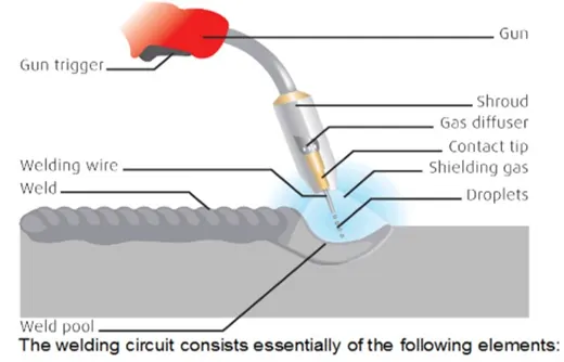
Gas Metal Arc Welding (GMAW), also known as Metal Inert Gas (MIG) welding, is a welding process that uses a consumable electrode and a shielding gas to join metals. In GMAW, a continuous solid wire electrode is fed through a welding gun, and an electrical current is passed through the wire to create an arc between the electrode and the work piece. The shielding gas, typically a mixture of argon and carbon dioxide, is used to protect the weld from atmospheric contamination.
Advantages of Gas Metal Arc Welding (GMAW):
High Productivity: GMAW offers high welding speeds and deposition rates, resulting in increased productivity compared to other welding processes. The continuous feeding of the electrode allows for long welding runs without the need for frequent electrode changes.
All-Position Welding: GMAW can be performed in all positions, including flat, horizontal, vertical, and overhead. This versatility makes it suitable for a wide range of welding applications.
Smooth and Clean Welds: GMAW produces smooth, clean, and aesthetically pleasing welds with minimal spatter. The use of shielding gas provides excellent protection against atmospheric contamination, resulting in high-quality welds.
Automation and Mechanization: GMAW is well-suited for automation and mechanization, allowing for precise and consistent welds in high-volume production environments. It is commonly used in robotic welding systems.
Versatility in Materials: GMAW can be used to weld a variety of metals, including carbon steel, stainless steel, aluminum, and other non-ferrous materials. Different types of solid wire electrodes and shielding gases are available to match specific material requirements.
Easy to Learn and Operate: GMAW is relatively easy to learn and operate, making it a popular choice for beginners and those new to welding. The process offers good control over the weld pool, allowing for consistent and repeatable results.
Disadvantages of Gas Metal Arc Welding (GMAW):
Sensitivity to Wind and Drafts: GMAW is sensitive to wind and drafts due to the reliance on shielding gas for protection. Wind or drafts can disrupt the shielding gas coverage, leading to poor weld quality and porosity.
Limited Welding in Outdoor Environments: GMAW is primarily suited for indoor welding applications due to the sensitivity to wind and drafts. It may not be suitable for outdoor welding or in environments with inadequate shielding gas protection.
Equipment Complexity: GMAW equipment can be more complex and expensive compared to some other welding processes. It requires a welding power source, wire feeder, shielding gas supply, and appropriate safety measures.
Limited Welding Thickness: GMAW is generally better suited for welding thicker materials, and it may not be suitable for welding very thin materials due to the higher heat input and potential distortion.
Applications of Gas Metal Arc Welding (GMAW):
Automotive Industry: GMAW is widely used in the automotive industry for welding vehicle frames, body panels, and other components.
Fabrication and Manufacturing: GMAW is commonly used in fabrication and manufacturing processes, including the welding of structural steel, metal furniture, appliances, and machinery.
Construction Industry: GMAW is employed in the construction industry for welding steel structures, beams, columns, and other building components.
Aerospace Industry: GMAW is utilized in the aerospace industry for welding aircraft components, such as fuselage sections, engine mounts, and brackets.
General Maintenance and Repair: GMAW is commonly used for maintenance and repair welding, including the repair of machinery, equipment, and metal structures.
Gas Metal Arc Welding (GMAW) is a versatile welding process that offers high productivity, clean welds, and the ability to weld a wide range of materials. It is widely used in various industries for its efficiency and effectiveness in joining metal components.
Submerged Arc Welding
Submerged Arc Welding (SAW) is a welding process that involves the formation of an arc between a continuously fed electrode and the work piece. The arc is shielded by a granular flux that covers the weld zone and protects it from atmospheric contamination.
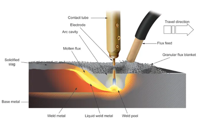
Advantages of Submerged Arc Welding (SAW):
High Deposition Rate: SAW is known for its high deposition rate, making it suitable for welding thick sections or large-scale projects where productivity is crucial.
Deep Penetration: The process generates deep and uniform penetration, resulting in strong weld joints with good fusion between the base metals.
Automatic Operation: SAW is often performed using automatic or semi-automatic equipment, allowing for consistent and repeatable welds. It is commonly used in applications that require high-volume production or long, continuous welds.
Excellent Weld Quality: The use of granular flux helps to create a protective atmosphere around the weld zone, preventing oxidation and minimizing the risk of defects such as porosity and inclusions. This results in high-quality welds with good mechanical properties.
Versatility in Materials: SAW can be used to weld a wide range of materials, including carbon steels, low alloy steels, stainless steels, and certain non-ferrous metals. It is particularly effective for welding thick sections or materials with high heat conductivity.
Reduced Welding Fume and Spatter: The submerged arc welding process produces less welding fume and spatter compared to other welding processes, contributing to a cleaner and safer working environment.
Disadvantages of Submerged Arc Welding (SAW):
Limited Accessibility: SAW is not suitable for welding in tight or confined spaces due to the equipment's size and the need for a flux layer to cover the weld zone. It is primarily used for flat or horizontal welding positions.
Equipment and Setup: SAW requires specialized equipment, including a power source, wire feeder, flux handling system, and a welding head or manipulator. The initial setup and maintenance of the equipment can be more complex compared to some other welding processes.
Flux Handling and Disposal: The use of flux in SAW requires proper handling and disposal procedures, as the flux can become contaminated with molten metal and other impurities during the welding process.
Limited Welding Positions: SAW is primarily used for flat or horizontal welding positions. Welding in vertical or overhead positions may require additional equipment or techniques to maintain the flux coverage and ensure proper weld quality.
Applications of Submerged Arc Welding (SAW):
Heavy Fabrication: SAW is commonly used in heavy fabrication industries, such as shipbuilding, bridge construction, pressure vessel manufacturing, and offshore structures.
Pipe Welding: SAW is widely used for welding longitudinal and circumferential seams in pipes, including oil and gas pipelines, water pipelines, and structural pipes.
Weld Overlay: SAW is often employed for weld overlay applications, where a protective layer of weld metal is deposited on the surface of a component to enhance its corrosion resistance or wear properties.
Railway Industry: SAW is used for welding railway tracks, railcar frames, and other components in the railway industry.
Wind Tower Manufacturing: SAW is utilized for welding the cylindrical sections of wind towers, which require high-quality and high-strength welds.
Steel Construction: SAW is employed in the construction of steel structures, such as buildings, bridges, and industrial frameworks.
Submerged Arc Welding (SAW) offers high productivity, excellent weld quality, and versatility in welding thick sections and various materials. It is commonly used in heavy fabrication, pipe welding, and other industries where efficient and reliable welding is required.
Gas Tungsten Arc Welding
Gas Tungsten Arc Welding (GTAW), also known as Tungsten Inert Gas (TIG) welding, is a welding process that uses a non-consumable tungsten electrode to create an arc and join metals. In GTAW, a shielding gas is typically used to protect the weld area from atmospheric contamination.
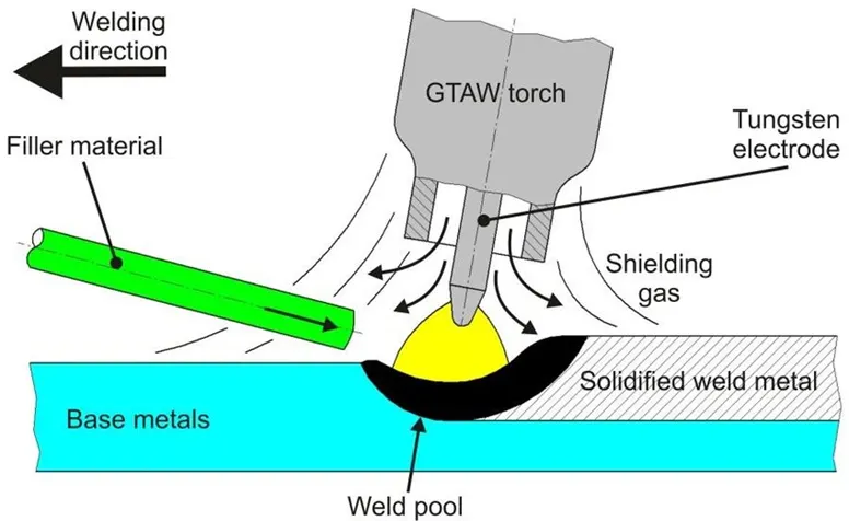
Advantages of Gas Tungsten Arc Welding (GTAW):
Precise Control: GTAW allows for precise control over the welding parameters, including heat input, arc length, and filler metal deposition. This makes it suitable for welding applications that require high accuracy and fine weld bead control.
High-Quality Welds: GTAW produces high-quality welds with excellent appearance and mechanical properties. The process enables the production of clean, defect-free welds with minimal spatter and distortion.
Versatility in Materials: GTAW can be used to weld a wide range of metals, including stainless steel, carbon steel, aluminum, nickel alloys, titanium, and copper alloys. It is particularly suitable for welding reactive metals and thin materials.
No Flux or Filler Material Required: GTAW does not require the use of flux or filler material, making it ideal for applications where a clean, slag-free weld is desired. It is commonly used for cosmetic welds, such as in the aerospace and automotive industries.
Welding in Various Positions: GTAW is suitable for welding in all positions, including flat, horizontal, vertical, and overhead. This versatility allows for greater flexibility in welding complex structures and components.
Heat Control: GTAW produces a concentrated, focused heat source, allowing for precise control over the heat-affected zone (HAZ). This is beneficial when welding heat-sensitive materials or performing welds in close proximity to critical areas.
Disadvantages of Gas Tungsten Arc Welding (GTAW):
Slower Welding Speed: GTAW is generally a slower welding process compared to other methods, such as Gas Metal Arc Welding (GMAW). The slower welding speed can lead to reduced productivity, especially when welding thick sections or large-scale projects.
Higher Skill Requirement: GTAW requires a higher level of skill and experience compared to some other welding processes. It demands good hand-eye coordination and the ability to control the torch, filler rod, and foot pedal simultaneously.
Equipment Complexity: GTAW equipment can be more complex and expensive compared to some other welding processes. It typically includes a power source, gas supply, TIG torch, and various controls and accessories.
Sensitivity to Joint Fit-up: GTAW is sensitive to joint fit-up, meaning that precise alignment and preparation of the joint are necessary for successful welds. Poor fit-up can result in weld defects and lack of fusion.
Applications of Gas Tungsten Arc Welding (GTAW):
Aerospace Industry: GTAW is widely used in the aerospace industry for welding critical components, such as aircraft engine parts, turbine blades, and fuel system components. The process's ability to produce high-quality welds with minimal distortion and heat input makes it suitable for these applications.
Automotive Industry: GTAW is used in the automotive industry for various applications, including welding exhaust systems, chassis components, and aluminum body panels. The process's precise control and clean welds are advantageous for these applications.
Food and Beverage Industry: GTAW is commonly employed in the food and beverage industry due to its ability to produce hygienic and sanitary welds. It is used for welding stainless steel pipes, tanks, and equipment in this industry.
Power Generation Industry: GTAW is used for welding components in the power generation industry, including nuclear power plants, fossil fuel power plants, and renewable energy facilities. It is suitable for welding critical components, such as boiler tubes, pressure vessels, and turbine parts.
Petrochemical Industry: GTAW is employed in the petrochemical industry for welding pipes, tanks, and equipment that handle corrosive materials and require high-quality welds.
Art and Sculpture: GTAW is used by artists and sculptors for creating intricate and detailed metal artwork. The process's fine control and ability to produce aesthetically pleasing welds make it a popular choice in the artistic field.
Gas Tungsten Arc Welding (GTAW) offers precise control, high-quality welds, and versatility in welding various metals. It is commonly used in industries such as aerospace, automotive, power generation, and food processing, where high-quality welds and fine control are essential.
Thermit Welding
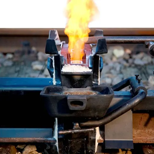
Thermit welding, also known as exothermic welding, is a process of joining metal components using a chemical reaction to produce intense heat. It is commonly used for applications where high-quality, permanent connections are required, such as railway tracks, pipelines, electrical grounding, and industrial applications.
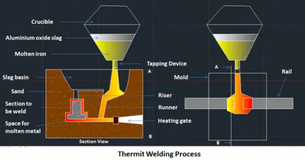
Thermit welding offers several advantages, including high strength, excellent electrical conductivity, corrosion resistance, and durability. However, it requires specialized equipment, skilled operators, and proper safety measures due to the intense heat generated during the process.
Gas Welding
Oxy-Acetylene Welding
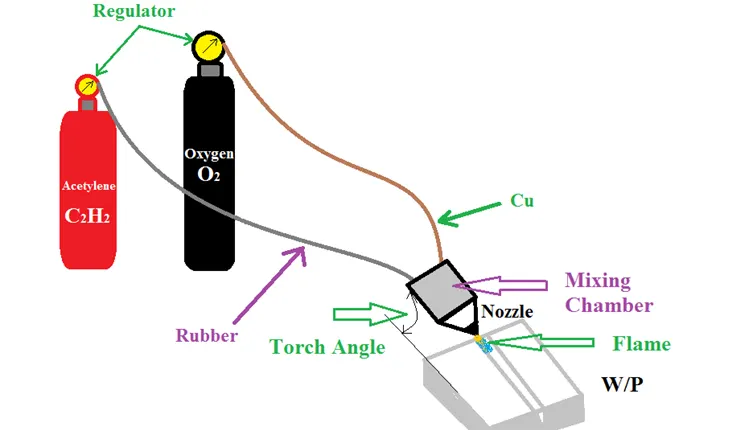
Oxy-Acetylene Welding, also known as oxy-fuel welding or gas welding, is a welding process that uses a combination of oxygen and acetylene gas to generate a high-temperature flame for melting and joining metals. It is one of the oldest and most versatile welding processes.
Advantages of Oxy-Acetylene Welding:
Versatility: Oxy-acetylene welding can be used to weld a wide range of metals, including carbon steel, stainless steel, cast iron, aluminum, and copper alloys. It is particularly suitable for welding thin sections and dissimilar metals.
Portability: Oxy-acetylene welding equipment is relatively portable compared to some other welding processes. It does not require electricity or complex machinery, making it suitable for on-site repairs and remote locations.
Control: Oxy-acetylene welding provides good control over the heat input, allowing for precise weld bead placement and manipulation. It is suitable for intricate and detailed welding applications.
Cost-effective: The equipment and consumables used in oxy-acetylene welding are generally more affordable compared to some other welding processes. This makes it a cost-effective option, especially for small-scale or occasional welding needs.
Disadvantages of Oxy-Acetylene Welding:
Lower Productivity: Oxy-acetylene welding is generally slower compared to processes like Gas Metal Arc Welding (GMAW) or Shielded Metal Arc Welding (SMAW). The slower welding speed can limit its application in high-volume production environments.
Limited Thickness Capability: Oxy-acetylene welding is not suitable for welding thick sections or heavy structural components. It is more commonly used for thin to medium thickness materials.
Safety Concerns: Oxy-acetylene welding involves the use of flammable gases and open flames, requiring proper safety precautions. The gases are highly combustible, and the open flame poses fire hazards.
Applications of Oxy-Acetylene Welding:
Repair and Maintenance: Oxy-acetylene welding is widely used for repair and maintenance work, such as patching or joining metal sheets, pipes, and equipment.
Plumbing and HVAC: Oxy-acetylene welding is commonly used in plumbing and HVAC (Heating, Ventilation, and Air Conditioning) applications for joining copper pipes and fittings.
Artistic and Ornamental Metalwork: Oxy-acetylene welding is favored by artists and craftsmen for creating intricate metal sculptures, ornamental ironwork, and decorative metal designs.
Automotive Restoration: Oxy-acetylene welding is often employed in automotive restoration projects, such as repairing body panels, fabricating exhaust systems, and joining sheet metal components.
Jewelry Making: Oxy-acetylene welding is sometimes used in jewelry making to join precious metals and create custom jewelry pieces.
Overall, oxy-acetylene welding offers versatility, portability, and control, making it a valuable welding process for various applications.
Oxy-Fuel Gas Welding
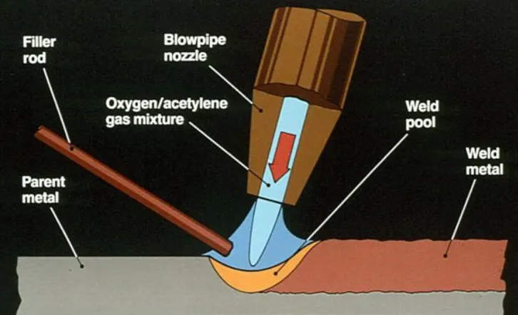
Oxy-Fuel Gas Welding, also known as oxy-fuel welding or gas welding, is a welding process that uses a combination of fuel gas and oxygen to produce a high-temperature flame for melting and joining metals. It is commonly used for welding ferrous and non-ferrous metals, including carbon steel, stainless steel, cast iron, aluminum, and copper alloys.
Advantages of Oxy-Fuel Gas Welding:
Versatility: Oxy-fuel gas welding can be used to weld a wide range of metals and alloys, making it suitable for various applications.
Portability: The equipment used in oxy-fuel gas welding is relatively portable and can be used in remote locations or areas without access to electricity.
Cost-effective: Oxy-fuel gas welding equipment and consumables are generally more affordable compared to some other welding processes.
Heat Control: Oxy-fuel gas welding allows for precise control of the heat input, making it suitable for welding thin materials and performing delicate welds.
Simple Operation: Oxy-fuel gas welding is a relatively simple process that can be quickly learned and mastered.
Disadvantages of Oxy-Fuel Gas Welding:
Limited Joint Strength: Oxy-fuel gas welding may not produce welds with the same level of strength as some other welding processes, such as arc welding or laser welding.
Slower Welding Speed: The welding speed in oxy-fuel gas welding is generally slower compared to processes like Gas Metal Arc Welding (GMAW) or Tungsten Inert Gas (TIG) welding.
Limited Thickness Capability: Oxy-fuel gas welding is more suitable for thin to medium thickness materials and may not be practical for thick sections.
Safety Concerns: Oxy-fuel gas welding involves the use of flammable gases and open flames, requiring proper safety precautions to prevent accidents or fire hazards.
Applications of Oxy-Fuel Gas Welding:
Construction: Oxy-fuel gas welding is used in construction for joining structural steel components, pipelines, and other metal structures.
Automotive: Oxy-fuel gas welding is utilized in automotive repair and restoration for welding body panels, exhaust systems, and other metal components.
Plumbing: Oxy-fuel gas welding is commonly used in plumbing for joining copper pipes and fittings.
Shipbuilding: Oxy-fuel gas welding is employed in shipbuilding for joining metal plates and structural components.
Artistic and Ornamental Metalwork: Oxy-fuel gas welding is favored by artists and craftsmen for creating artistic metal sculptures, ornamental ironwork, and custom metal designs.
Oxy-fuel gas welding has been largely replaced by other welding processes, such as Gas Metal Arc Welding (GMAW) and Tungsten Inert Gas (TIG) welding, in many industrial applications due to their higher efficiency, faster welding speeds, and better control. However, oxy-fuel gas welding remains a valuable and widely used process in certain industries and applications.
5. The 3-2-1 principle
The 3-2-1 principle, also known as the basic concept of fixturing, is a fundamental guideline used in fixture design and setup. It provides a systematic approach to properly locate and secure a work piece in a fixture for accurate and repeatable machining or assembly processes.
The 3-2-1 principle consists of three primary locating points, two secondary locating points, and one clamping point. Here's a breakdown of each component:
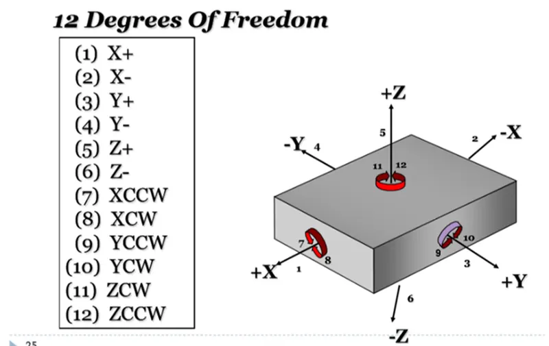
Three Primary Locating Points: These are three contact points that constrain the work piece in three mutually perpendicular directions. They provide stability and ensure proper alignment. The primary locating points are typically established using precision pins or dowels that fit into corresponding holes or slots on the work piece. Together, the three locators restrict 5 degree of freedom (1 axial movement and 4 radial movement).
Two Secondary Locating Points: These are two additional contact points that further restrict the movement of the work piece. The secondary locating points are often created using additional pins, pads, or surfaces that interact with the work piece to prevent rotation or shifting.This restrict 4 axial movement.
One Clamping Point: This is the point where the work piece is securely clamped or held in place within the fixture. The clamping point ensures that the work piece remains fixed during machining or assembly operations. It can be achieved using various clamping mechanisms such as clamps, screws, or hydraulic/pneumatic devices. This restrict 2 axial movement.
In order to simplify we can consider total degree of freedom as 6 and 3-2-1 principle is restricting all the 6 degree of freedom.
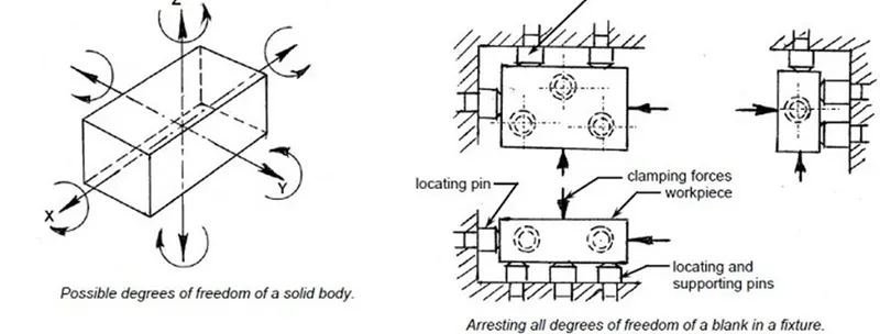
The 3-2-1 principle provides a reliable and repeatable method for positioning and securing a work piece in a fixture, minimizing dimensional errors and ensuring consistent results. It is widely used in manufacturing processes such as machining, welding, and assembly to achieve accurate and efficient production.
6. Body Coordinate system
The body coordinate system has been widely used in the automotive industry for drawing of body parts, product and process design. The body coordinate system typically follows a three-dimensional Cartesian coordinate system, where three mutually perpendicular axes are used to define the X, Y, and Z directions.
The body coordinate system refers to a coordinate system used to define the position, orientation, and measurements of various components and features of a vehicle's body structure. It serves as a standardized reference system for design, engineering, and manufacturing processes.
A coordinate system is a reference system consisting of a set of points, line and surfaces used to define the positions of points in space in either two or three dimensions.
In general body coordinate system is also called as car line and body line.
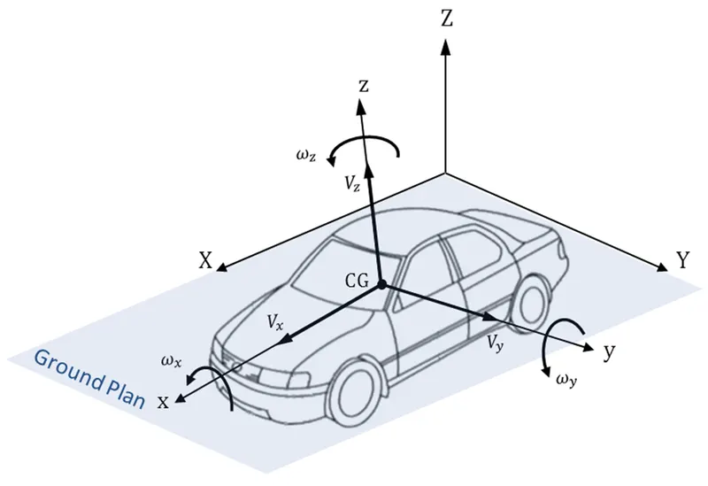
X-Axis: Longitudinal Direction (Front O Line - FOL)
Y-Axis: Transverse Direction (Center O Line – COL)
Z-Axis: Vertical Direction (Bottom O Line – BOL)
The origin of the body coordinate system (OX) is defined at the front center of a vehicle, it indicates a length of car and the coordinate system (OZ) is below its underbody indicates height of a car, and the body coordinate system (OY) its starting point is the center of car body indicates width of car.
The body coordinate system is essential for ensuring consistency and accuracy in various manufacturing processes related to the BIW, such as component alignment, measurement, assembly, and quality control. It allows different teams and stakeholders involved in the production of the vehicle's body structure to communicate and work with a common reference frame.
7. Body plane system & its essentials
Body planes are the reference planes in an automotive car. These planes are used to define the GD&T of all car parts in an automotive domain. The body plane system refers to a set of reference planes used to define the orientation, positioning, and measurements of components and features in the body structure of a vehicle. It provides a standardized framework for design, engineering, manufacturing, and quality control processes.
Body planes are 3 mutually perpendicular imaginary planes. These are generally considered to be present at the driver position or sometimes at the engine location or at the front end of the car, depending on the customer. Each plane serves a specific purpose and helps in defining the spatial relationships of various elements within the BIW.
These body planes are called as
FOL: Front “O” Line
COL: Center “O” Line
BOL: Body “O” Line
The measurement along FOL or X-Axis is called as F/A Front Aft
The measurement along COL or Y-Axis is called as C/C Cross Car
The measurement along BOL or Z-Axis is called as U/DUP Down
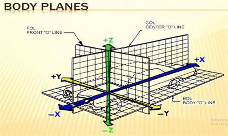
Bodyline dimensions are essential for the below mentioned reasons:
Standardization: The body plane system provides a standardized framework for defining and measuring spatial relationships within the BIW. It ensures consistent communication and understanding among design, engineering, and manufacturing teams, reducing errors and inconsistencies in component positioning and alignment.
Accuracy: By using a well-defined set of reference planes, the body plane system helps ensure accurate measurements and alignments of components. This accuracy is crucial for achieving proper fit and function of various parts within the BIW.
Efficiency: The body plane system facilitates efficient manufacturing processes by providing a common reference for component positioning and assembly. It helps streamline production workflows, reduces setup time, and improves overall productivity.
Quality Control: With the body plane system, it becomes easier to verify the dimensional accuracy and alignment of components during quality control processes. The reference planes allow for precise measurement and assessment of component deviations, helping identify and rectify any manufacturing or assembly issues.
Design Flexibility: The body plane system allows for flexible design iterations and modifications while maintaining consistency in dimensional relationships. Design changes can be easily accommodated within the established framework of the reference planes, ensuring compatibility and integration of new components.
Collaboration: The body plane system promotes effective collaboration among different teams involved in the BIW manufacturing process. Designers, engineers, and manufacturers can work together using a common language and reference points, enhancing communication and coordination.