Week 2:- BiW Fixture Basics Challenge
1. PROJECT EXECUTION ACTIVITY:
| STAGE NO. | STAGE | PROCESS |
| 1 | RFQ required | RFQ stands for "Request for Quotation". Customer lists its requirements in form of data. |
| 2 | 1st specification discussion meeting | Customer requirements are studied. Documents are prepared like technical offer, commercial offer, time duration, etc. |
| 3 | Offer submission | Offer submitted so that customer can check if the offer is according to his requirement. |
| 4 | LOI/PO receipt | Customer will compares other offers from different vendors, and will generate PO giving to ahead for next steps. Also 3D data input will be received by customer mentioning its requirements in detail |
| 5 | Schedule preparation | All including activities schedule is prepared in step-wise manner. |
| 6 | BOM preparation | Bill of material is prepared for parts (motor, cylinders,etc)) |
| 7 | Design Concept preparation | Concept is prepared based on all the data |
| 8 | Customer Approval | Customer will check if the concept is going in right direction, and also if any changes required will be updated in the concept. |
| 9 | Detailing and Drawing release | Data is released in drawing form to manufacturing department |
| 10 | Manufacturing/ BOP ordering | Manufacturing will begin and orders will be placed for standard products like cylinders, sensors,etc. and Quality inspection will be done of manufactured as well as purchased parts to make sure it matches the requirement |
| 11 | Mechanical/ Electrical Assembly | All parts are assembled |
| 12 | Quality Inspection | Inspection will be done to check if the assembly is done as per the drawing, CMM inspection is done for checking relative position of different parts |
| 13 | Internal trial & testing | Fixture is tested for clamping acuracy, pin acuracy,etc |
| 14 | Online trial | Trial is done with control panel in automated way |
| 15 | Packaging | fixture is packaged carefully so as to not damage it during transportation |
| 16 | Dispatch | fixture is send to the customer |
| 17 | Installation as per layout | installation is done as per the designed layout that has been designed at initial level |
| 18 | Trials & training at customer | Production trial, online trials, etc. will be done. Worker will trained so that they can start working on the fixture. |
| 19 | Buy-off meeting | If modifications are required from customer side, or some parts were missed in initial RFQ then that is addresed and new requests are generated. |
| 20 | Final Handover | Fixture is completely handed over to the customer |
2. TYPES OF JOINING PROCESSES:
Generally joining processes are of two types:
- Mechanical joining (riveting, fastening, etc)
- Metallurgical joining (welding, brazing, etc)
METALLURGICAL JOINING:
RESISTANCE WELDING:
- Resistance Spot welding:
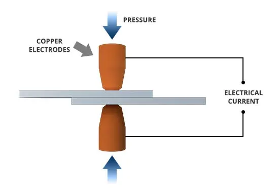
Spot welding (also known as resistance spot welding) is a resistance welding process. This welding process is used primarily for welding two or more metal sheets together by applying pressure and heat from an electric current to the weld area.
It works by contacting copper alloy electrodes (usually Copper-chromium or zirconium alloy electrode) to the sheet surfaces, whereby pressure and electric current are applied and heat is generated by the passage of current through resistive materials such as low carbon steels.
- Resistance Seam welding:
Seam welding is the joining of work pieces made of similar or dissimilar materials along a continuous seam. Resistance Seam welding is a variation of resistance spot welding with the main difference being that the welding electrodes are motor driven wheels rather than stationary rods.
Ideal for sheet metal fabrication, this welding method passes an electric current through the sheets of metals to be joined while they are held together by a mechanical force in a lap configuration between shaped copper electrodes.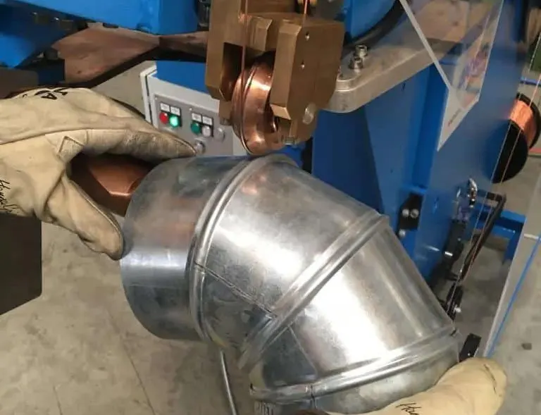
- Resistance Projection welding:
Projection welding is one kind of resistance weld where the shape or design of the part is used to make subtle point contacts to concentrate the current during welding. Mostly, in almost all applications with various small projections are molded on single parts surfaces which need to weld.
It’s applicable on thick metals where the measures to be welded differ in sizes by 5:1. Weld current can be concentrated on to the small area of the projection to make heat on the required location by projection on that surface.
ARC WELDING
- Manual metal arc welding:
Manual metal arc welding (MMA or MMAW), also known as flux shielded arc welding or stick welding, is a process where the arc is struck between an electrode flux coated metal rod and the work piece. Both the rod and the surface of the work piece melt to create a weld.
The process allows only short lengths of weld to be produced before a new electrode needs to be inserted in the welding electrode holder. Weld penetration is low and the quality of the finished weld deposit is highly dependent on the skill of the welder.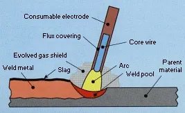
- Gas-Shielded Metal Arc Welding [Metal Inert Gas Welding (MIG)]:
Metal Inert Gas (MIG) welding is an arc welding process that uses a continuous solid wire electrode heated and fed into the weld pool from a welding gun. The two base materials are melted together forming a join. The gun feeds a shielding gas alongside the electrode helping protect the weld pool from airborne contaminants.
MIG/MAG welding is a versatile technique suitable for both thin sheet and thick section components. Manual MIG/MAG welding is often referred as a semi-automatic process, as the wire feed rate and arc length are controlled by the power source, but the travel speed and wire position are under manual control.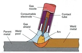
- Gas-Shielded Tungsten Arc Welding [Tungsten Inert Gas Welding (TIG)]:
Tungsten Inert Gas (TIG) welding, also known as Gas Tungsten Arc Welding (GTAW) is an arc welding process that produces the weld with a non-consumable tungsten electrode. In the TIG welding process the arc is formed between a pointed tungsten electrode and the workpiece in an inert atmosphere of argon or helium.
The small intense arc provided by the pointed electrode is ideal for high quality and precision welding. Because the electrode is not consumed during welding, the TIG welder does not have to balance the heat input from the arc as the metal is deposited from the melting electrode. When filler metal is required, it must be added separately to the weldpool.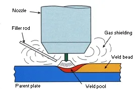
- Submerged Arc Welding:
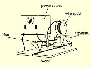
Submerged-arc welding (SAW) is a common arc welding process that involves the formation of an arc between a continuously fed electrode and the workpiece. A blanket of powdered flux generates a protective gas shield and a slag (and may also be used to add alloying elements to the weld pool) which protects the weld zone.
A shielding gas is not required. The arc is submerged beneath the flux blanket and is not normally visible during welding.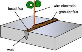
- Plasma Arc Welding:
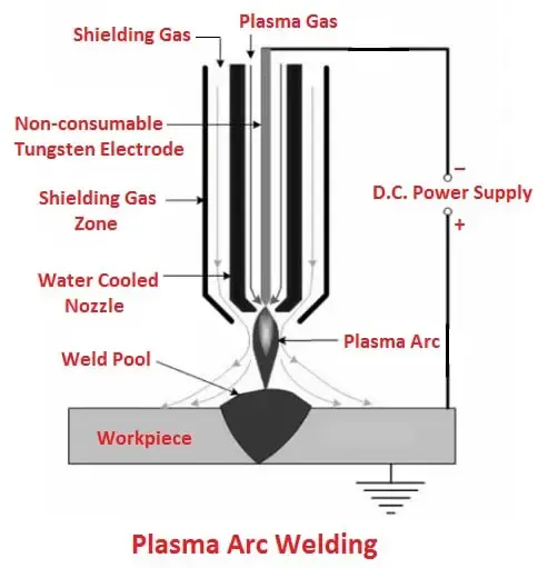
Plasma arc welding is an arc welding process using heat produced by a compressed arc between a tungsten non-consumable electrode and another workpiece (transferred arc process) or water-cooled constricting nozzle (non-transferred arc process).
The PAW works on the principle when a sufficient amount of energy is provided to any inert gas, some of its electrons are released from their nucleus but travel with it.
After the electrons move, the atoms are converted into a hot ionized state. This is the most common condition of the substance which is known as the fourth state of matter.
Ionized atoms have high temperatures that are used to join the two plates. This is the basic principle of PAW. This welding is a form of TIG welding in which a non-consumable tungsten electrode is used to generate the arc.
MECHANICAL JOINING:
- Mechanical Fastening: The joining of material combination which cannot be easily welded such as pre-painted steels or dissimilar metals. It is used where high fatigue life is critical compared to static strength and where a long tool life is of relatice importance.
Screws and bolts are a reliable and inexpensive method of mechanical fastening. - Self Piercing Riveting:
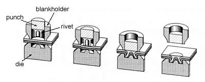
Self-piercing riveting is a high-speed mechanical fastening process for point joining sheet material, typically steels and aluminium alloys. It is a single-step technique, generally using a semi-tubular rivet to clinch the sheets in a mechanical joint. There is also a process variant which utilises solid rivets.
As the name suggests, pre-drilled holes are not required, allowing the joint to be made rapidly in one operation. The process cycle is shown in cross-section below.
- Hemming Process:
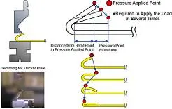
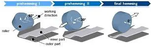
Hemming in sheet metal operations refers to the bending of a sheet metal edge onto itself. It is very similar to edge stitching in clothes. Similar to how an edge stitch strengthens the edge and makes it more durable, a hem imparts strength to the metal edge and improves its appearance. The edge of one part may also be folded onto another part to create a joint.
Hemming is usually done in two stages. The first stage creates an acute bend using acute tooling (V die) followed by a flattening of the return flange using a flattening die.
- Adhesive bonding:
It is used to fasten two surfaces together, usually producing a smooth bond.
This joining technique involves gluing, epoxies or various plastic agents that bond by evaporation of a solvent or by curing a bonding agent with heat, pressure, or time.
4. FUSION WELDING:
Fusion welding is a process that uses heat to join or fuse two or more materials by heating them to melting point. The process may or may not require the use a filler material. External application of pressure is not required for fusion welding processes, except for resistance welding, where substantial contact pressure is required during welding for sound joining.
Fusion welding processes can be grouped according to the source of the heat, for example, electric arc, gas, electrical resistance and high energy.
These processes include:
Arc Welding Processes - with the most common processes being:
Shielded Metal Arc Welding (SMAW), also known as manual metal arc welding (MMA or MMAW), flux shielded arc welding or stick welding. Suitable for welding ferrous and non-ferrous materials in all positions.
Metal Inert Gas Welding (MIG) and Metal Active Gas Welding (MAG), also known as Gas Metal Arc Welding (GMAW). MIG and MAG welding are the most common arc welding processes, in which an electric arc forms between a consumable wire electrode and the workpiece leading them to melt and join. Both use a shielding gas to protect the weld from airborne contaminants, or oxidation in the case of MIG welding.
Tungsten Inert Gas Welding (TIG), also known as Gas Tungsten Arc Welding (GTAW). This arc process uses a non-consumable tungsten electrode to create the arc between the electrode and the base plate. An inert shielding gas is used to protect from oxidation or other atmospheric contamination. This process can be used autogenously on thin parts, but will require the addition of a wire, rod, or consumable to be added for thicker parts.
Submerged Arc Welding (SAW). This frequently-used arc welding process uses a continuously-fed consumable electrode and a blanket of fusible flux which becomes conductive when molten and provides a current path between the workpiece and the electrode. The flux also prevents spatter and sparks while suppressing ultraviolet radiation and fumes.
Flux Cored Arc Welding (FCAW). Developed as an alternative to SMAW, this process uses a continuously fed consumable electrode with a flux and a constant voltage or constant current power supply. Sometimes using a shielding gas this process can also just use the flux to provide protection from the atmosphere.
Gas Welding Processes - the most common process being:
Oxy-Fuel Welding, also known as Oxyacetylene Welding but commonly called gas welding, this process uses a hand-held torch or blow pipe and a mixture of oxygen and acetylene which combusts to create a flame.
Resistance Welding Processes
Resistance Spot Welding. This fast welding process delivers heat between two electrodes according to the material properties and thickness of the workpieces. The welding current is concentrated to a small spot as the workpieces are simultaneously clamped together.
Resistance Seam Welding. This variant of spot welding produces a series of overlapping nuggets of a continuous joint by replacing conventional spot welding electrodes with wheels which rotate as the workpieces are fed between them.
High Energy Welding Processes - with the main ones being:
Electron Beam Welding (EBW). This fusion process is performed under vacuum conditions, using a beam of high velocity electrons to melt the workpieces as the electrons generate heat upon penetration into the material. Welds are often deep and narrow.
Laser Beam Welding (LBW). Often used in high volume applications, LBW uses a laser beam to provide a concentrated heat source with high levels of accuracy which can be used to join metal and polymers.
5. 3-2-1 PRINCIPLE:
(T= translation, R= Rotation)
A workpiece has 6 DOF (degree of freedom) i.e. 3T (x,y and z) , 3R (x-axis, y-axis and z- axis)
3 = Minimum three blocks supporting the component which forms a plane. DOF arrested = 1T, 2R
2 = Pin inserted into a hole. DOF arrested = 2T
1 = Pin inserted at another hole in same plane as previous hole. DOF arrested = 1R
6. BODY CO-ORDINATE SYSTEM:
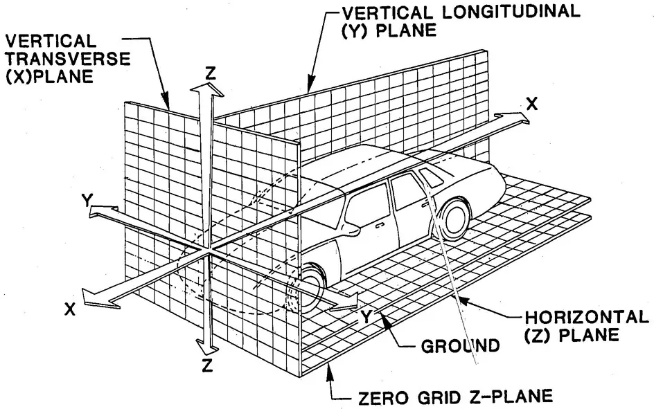
A co-ordinate system is a reference system consisting of a set of points, lines and surfaces.
In general, BCS (Body Co-ordinate system) is called as Car line and Body line.
The origin of BCS (OX) is defined at the front center of a vehicle. It indicates a length of the car and the BCS (OZ) is below its underbody indicates height of the car and the BCS (OY) its stating point is the center of car indicates widht of the car.
7. BODY PLANE SYSTEM:
Body planes (BP) are reference planes in a automotive car. These planes are used to define the GD&T of all car parts ina automotive domain.
These are 3 mutually perpendicular imaginary planes. These are generally considered to be present at the driver position or sometimes at the engine location or at the front end of the car, depending on the customer.
Measurements from the BP to the parts are called as bodyline dimensions.
These BP are called as
- FOL Front"O" Line
- COL Center "O" Line
- BOL Body "O" Line
- The measurement along FOL or X axis is called as F/A front aft
- The measurement along COL or Y axis is called as C/C Cross car
- The measurement along BOL or Z axis is called as U/D Up Down
Body Planes are essential because
- It define exact position of each product in the vehicle w.r.t/ a fixed origin
- It ensures flawless design for assembly
- While designing lines all the designs are carried out relative to the bodyline, viz., fixtures, turn tables, etc.
- It assists in easy location of different parts in a vehicle
- It aims in creating a standardized system
- It assists in Quality checks