Week 2:- BiW Fixture Basics Challenge
1. What is the process of project execution activity?
Project execution is the stage of the project where everything has been planned is put into action. The main objectives are:
- To keep the work on track
- To organize team members
- To manage timelines
- To make sure the work is being done according to the original plan.
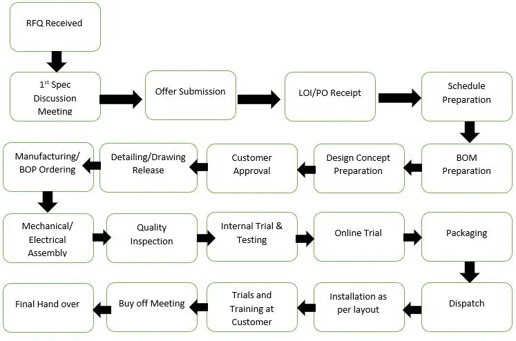
1. RFQ:
- Request For Quotation (RFQ) is the first step involved in project execution phase.
- In this activity the customer quotes his/her recquirements and specifications regarding the project in a detailed document.
- Besides the technical offer, commercial offer, expected timeline of the project and oether details are also provided.
2. First spec discussion meeting:
- After the RFQ is received, there will be a discussion meeting about the technical offer, commercial offer, project execution, timeline required to complete the project and the crew will make a final decision based on the result.
- In addition, the time required to complete the project from the begining of data study,3d concept design, simulation validation, quality check,2D drawing release,manufacturing,etc., are calculated and prepared in the technical offer.
- Based on technical offer commercial offer will be finalized.
3. Offer submission:
- After the finilization the offer is submitted to the customer end.
- The customer will also receive more offers from other companies. The customer will go through the offers and analyse it.
4. LOI/PO receipt:
- After the customer has analysed the offers in all aspects, the final LOI/PO (Purchase Order) will be issued to the respective manufacturer end.
- Once the PO is received the project work has to be started by preparing schedules.
5. Schedule preparation:
- After receiving the PO, the project schedule preparation will be done to meet the project deadlines specified by the customer in order to complete the project.
- All the stages in the project are considered for the calculation of time recquired to complete the actions such as kick-off meeting, design data study, DAP, simulate quality check, 2D detailing, drawing check, release of BOM, manufacturing, boughts out of electrical and mechanical components, assembly of fixture, paints,etc.,
- The above mentioned activities are traced in the schedule preparation chart.
- If the date obtained does not match with the dead lines, then the schedule is revised accordingly and meetings are held.
6. BOM preparation:
- Bill of materials like cylinders, motors,bolts, nuts,etc., are listed and prepared.
7. Design concept preparation:
- Before this step a complete study of design data is done as per the customer recquirements.
- During the design data study activities some rough sketches are done to get the flow of design.
- It undergoes conceptualization of basic data like spot plan,cycle time,etc.,
- To avoid collision of weld guns with the clamps while traveling, spot plan is made in the initial stage.
8. Customer approval:
- In this step the customer reviews the design data and checks whether the design fulfills the recquirements of the proposed design or not based on the technical offer.
- If it is ok then the customer will finalize the approval and if it is not ok, several steps are to be taken to re examine the schedule and design. After that the result must be submitted for approval.
9. Detailing and drawing release:
- Once the customer approved the project, the detailed drawings and designs are prepared at the manufacturer end.
- It is released for all the parts recquired with the appropriate dimensions,tolerances,quantity,specifications,etc.,
10. Manufacturing/BOP ordering:
- In this stage the recquired components for manufacturing like motors,cylinders,sensors,gripper,etc., are ordered as per the specifications recquired.
11. Mechanical/ Electrical assembly:
- After all the parts from the BOP ordering are received, they are subjected to quality check by the quality department with respect to the specifications.
- Then the mechanical and electrical parts are assembled.
12. Quality inspection:
- Quality checking is again done once after the assembly is finished.
- The dimensions, positional accuracy, coordinates are checked by using CMM machine.
- Only the approved assembly is passed to the next level, rest is sent back to the assembly for re-assembly work.
13. Internal trial& testing:
- The next to quality check is the internal trial which is done to evaluate the operation of the fixture.
- It is the inhouse testing where the seating of the assembly/panel, clamping,postion of pins into holes are checked for proper outcome.
14. Online trial:
- It is done in automated mode by using electrical connections.The process sequence is checked as per the designed way in front of the customer for further approval.
15. Packaging:
- It is done to avoid damage during transportation which may affect the proper function and aesthetic look of the fixture.
- Hence proper packaging is done to ensure the geometry of the fixture.
16. Dispatch:
- After the fixture has been properly packed, it will be dipatched to the customer end with the mentioned address.
17. Installation as per layout:
- At the initial stage itself the layout for the fixture assembly is prepared which defines the space for the robots,fixture,etc.,
- The layout is prepared by considering the functionality,application, process sequence,etc., Hence the installation is to be done as per the layout.
18. Trials and training at customer:
- Production trials will be carried out at the customers end. As the technical offer defines the 'n' number of assemblies will be completed in 8hrs/ 12hrs shift.
- So the production trial is carried out to ensure the capability of the fixture as per the technical offer terms.
- Once it is achieved, training will be provided to the workers, engineers, operators about handling the fixture like loading, unloading of the part,etc., also the sequence of process will be explained.
19. Buy off meeting:
- In this meeting the customer reviews are taken and in some cases the customer may ask for some additional features to be included in the fixture.
- Those requests are analysed and finalized by conducting meetings.
- All the doubts from the customer end are clarified and process is moved further.
20. Final handover:
- In this step, the product is finally handed over to the customer.
- The documents like clamp validation document, ergo sheets, BOMs,etc., will also be handed over to the customer along with the fixture.
- We can carry a proof for our work done as documents.
- Every automobile industries will follow some document standards like ISO & IATF.
- IATF(International Automotive Task Force) is a group which is followed by most industries now-a-days.
2. What are the types of joining processes?
•Joining includes welding, brazing, soldering, adhesive bonding of materials.
• They produce permanent joint between the parts to be assembled.
• They cannot be separated easily by application of forces.
• They are mainly used to assemble many parts to make a system.
• Welding is a metal joining process in which two or more parts are joined or coalesced at their contacting surfaces by suitable application of heat or/and pressure.
• Some times, welding is done just by applying heat alone, with no pressure applied
• In some cases, both heat and pressure are applied; and in other cases only pressure is applied, without any external heat.
• In some welding processes a filler material is added to facilitate coalescence(Joining)
1. Brazing and Soldering: Melting of filler rod only
• Brazing: higher temperature, ~brass filler, strong
• Soldering: lower temp, ~tin-lead filler, weak
2. Welding: Melting of filler rod and base metals
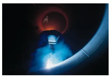
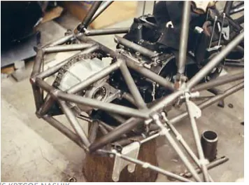
Classification of Welding processes:-
• Arc Welding
1)Gas tungsten arc welding(TIG) or (GTAW)
2)Gas metal arc welding(MIG) or (GMAW)
3)Shielded metal arc welding(SMAW)
4)Submerged arc welding
5)Plasma arc welding
6)Flux cored arc welding(FCAW)
•Resistance welding
1)Spot welding
2)seam welding
3)Projection welding
4)Resistance butt welding
• Gas welding
1)Oxy-acetylene welding
2) Oxy-hydrogen welding
3)Air -acetylene welding
4)Pressure Gas welding
• Thermo chemical welding Process
1)Thermit welding
2)Atomic hydrogen welding
• Radient energy welding Process
1)Electron beam welding
2)Laser beam welding.
Types of welding:
Welding processes can be broadly classified into
(i) fusion(non-pressure) welding, and (ii) solid state
welding(pressure welding)
Fusion welding:
In fusion-welding processes, heat is applied to melt the basemetals. In many fusion welding processes, a filler metal is added to the molten pool during welding to facilitate the process andprovide strength to the welded joint. When no filler metal is used, that fusion welding operation is referred to as Autogenous weld.
Types: Arc welding, Resistance welding, Gas welding, electron
beam welding, laser welding
Solid State Welding:
• In this method, joining is done by application of pressure only or a combination of heat and pressure.
• Even if heat is used, the temperature in the process is less than the melting point of the metals being welded (unlike in fusion welding).
• No filler metal is utilized. Diffusion welding: Two part surfaces are held together under pressure at elevated temperature and the parts join by solid state diffusion. Friction welding/Stir welding: Joining occurs by the heat of friction and plastic deformation between two surfaces. Ultrasonic welding: Moderate pressure is applied between the two parts and an oscillating motion at ultrasonic frequencies is used in a direction parallel to the contacting surfaces.
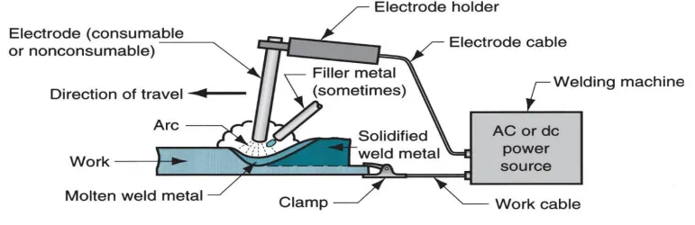
Electrodes
• Two types of electrodes are used: consumable and non-consumable
• Consumable electrodes: Present in rod or wire form with 200 to 450 mm length and less than 10 mm diameter. This is the source of filler rod in arc welding. The electrode is consumed by the arc during the welding process and added to the
weld joint as filler metal. The consumable electrodes will be changed periodically as it is consumed for each welding trials. This becomes a disadvantage for welder and reduces the production rate.
• Non-Consumable electrodes:
The electrodes are not consumed during arc welding. Though this is the case, some depletion occurs because of vaporization.Filler metal must be supplied by means of a separate wire that is fed into the weld pool.
Arc shielding
Shielding gas:
This covers the arc, electrode tip and weld pool from external atmosphere. Themetals being joined are chemically reactive to oxygen, nitrogen, and hydrogen in the atmosphere. So the shielding is done with a blanket of gas or flux, or both, which inhibit exposure of the weld metal to air.
Common shielding gas: Argon, Helium
Flux:Used mainly to protect the weld region from formation of oxides and other unwanted contaminants, or to dissolve them and facilitate removal. During welding, the flux melts and covers the weld region giving protection and itshould be removed by brushing as it is hardened.
Additional function, other than giving protection: stabilize the arc, and reduce spattering.
Power source in arc welding:
Both AC and DC can be used; DC is advantageous as better arc control is possible.
Polarity:
Straight polarity in which work piece is positive and electrode is negative is suitable
for shallow penetration (like in sheets) and joints with wide gaps.
Reverse polarity in which work piece is negative and electrode is positive is suitable
for deeper welds.
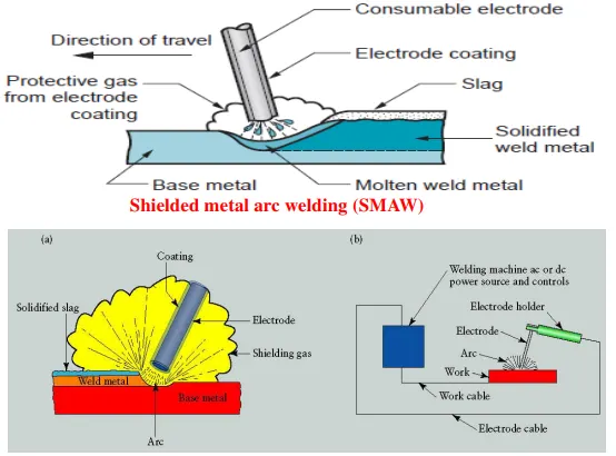
Arc welding processes with consumable electrodes
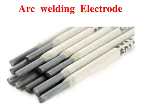
• Shielded metal arc welding (SMAW):
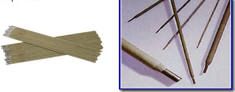
- In this process, a consumable electrode consisting of a filler metal rod which
is coated with chemicals that provide flux and shielding, is used.
- Generally the filler metal has chemical composition very close to base metal.
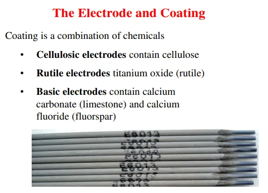
- Filler rod coating: Coating consists of powdered cellulose (cotton and wood
powders) mixed with oxides, carbonates, combined using a silicate binder.
- This coating provides protective layer to the weld pool and stabilizes the arc.
- current: < 300 A; Voltage: 15 – 45 V.
- Applications: ship building, construction, machine structures etc.
- Materials: grades of steel, stainless steel etc. are welded. Al, Cu, Ti alloys are
not welding using SMAW.
- Disadvantages: repeated change of electrodes, current maintained in typical
range
Submerged arc welding (SAW):
- In submerged arc welding also known as hidden arc welding,submerged melt welding or sub-arc welding the arc is struck between a metal electrode and the work piece under a blanket of granular flux.
-The welding action takes place under the flux layer without any visible arc, spatter, smoke or flash
-In this process, a continuous bare electrode wire is used.
-The shielding is provided by external granular flux through hopper.
- Granular flux is provided just before the weld arc.
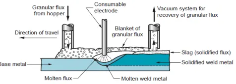
- granular flux completely provides protection from sparks, spatter, and radiation and hence safety glasses, gloves can be
avoided.
-some part of flux gets melted and forms a glassy layer.
Application:
longitudinal and circumferential welds for large diameter pipes, tanks, and pressure vessels; welded components for heavy
machinery. Steel plates of 25 mm thick are welded.
Gas metal arc welding (GMAW) OR (MIG):-
- In this process, electrode is a consumable wire (0.8 to 6.5 mm diameter).
- shielding gas is provided separately over arc by a pipe
- Shielding gas: Helium, Argon, mixture of gases; used mainly for Al alloys.
- active gases like CO2 is used for welding steel grade material.
- As compared to SMAW, GMAW can be used for multiple weld passes as there is no deposition of slag and hence no brushing involved. (advantage)
- advantage: automation of welding possible as continuous weld wires are used, and not sticks as in SMAW.
- Also called MIG (metal inert gas) welding, CO2 welding (when CO2 is used).
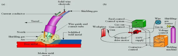
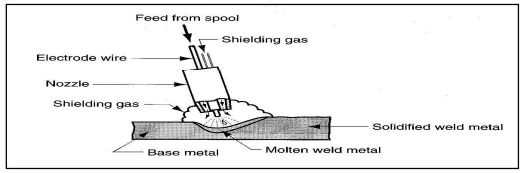
• Gas metal arc welding (GMAW), sometimes referred as metal inert gas MIG welding, is a welding process in which an electric arc is formed between a consumable wire electrode and the work piece metal(s), which heats the work piece metal(s), causing them to melt, and join.
• Along with the wire electrode, a shielding gas is fed through the welding gun, which shields the process from contaminants in the air.
• A constant voltage, direct current power source is most commonly used with GMAW.
• shielding gases are necessary for gas metal arc welding to protect the welding area from atmospheric gases such as nitrogen and oxygen, which can cause fusion defects, porosity.
Arc welding processes with non consumable electrodes
Gas Tungsten Arc Welding (GTAW):
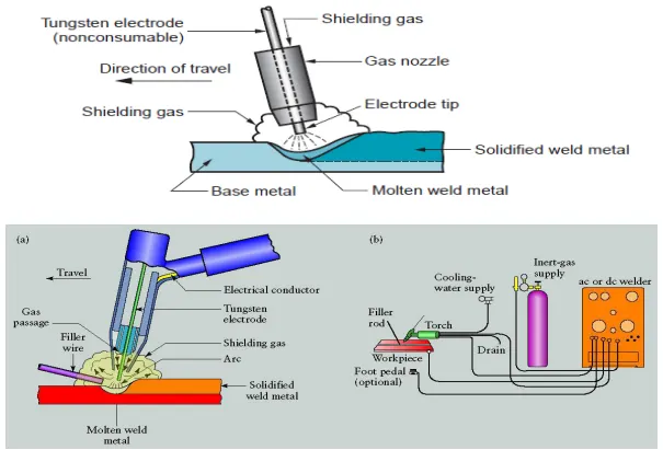
- It uses a non-consumable tungsten electrode and shielding gas (inert gas) for shielding.
- Also called tungsten inert gas welding (TIG)
- usage of filler wire is optional and is heated by arc and not transferred across the arc.
- Tungsten is a good electrode material due to its high melting point of 3400°C.
- Advantages: high quality welds, no weld spatter because no filler metal is transferred across the arc.
- High skill level required to achieve good weld.
- Difficult to automate.
Flux Cored Arc Welding (FCAW):-
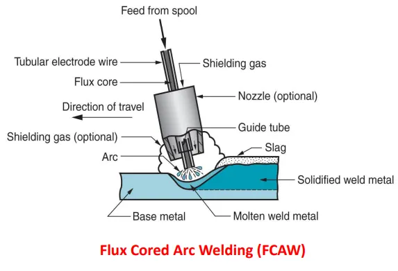
• FCAW is an arc welding process in which the heat for melting is
obtained from an arc between a hollow consumable tubular electrode
and the work piece.
• The hollow electrode is filled with flux. That is why the process is
called flux cored arc welding process.
• This process is economical compared to SMAW and GAW.
• Metals over a wide range of thickness can be welded.
• Because of its higher productivity FCAW is finding wide applications
for shop fabrication, field erection work and maintenance.
• It can be used for welding of cast iron, low carbon steel, low and high
alloy steels and stainless steels.
• Well known applications include machine frames, bulldozer blades,
bridge grinders, furnace tubes and diesel engine bodies.
Plasma arc welding
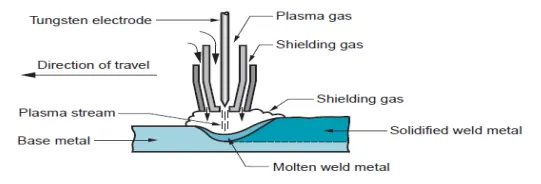
- It is a variety of gas tungsten arc welding in which a constricted (narrow) plasma arc is used for welding.
- In PAW, a tungsten electrode is kept in a nozzle that focuses a high velocity stream of inert gas into the region of the arc to form a high velocity, intensely hot plasma arc stream.
- Temperatures in plasma arc welding reach 17,000°C. This is mainly due to the constriction of the arc. The input power is highly concentrated to produce a plasma jet of small diameter and very high power density.
- The process can be used to weld almost any material, including tungsten.
Resistance Welding:-
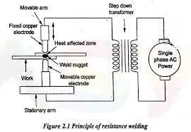
• Resistance welding is the process in which two or more parts are welded by the coordinated and regulated use of
heat and pressure.
• The heat in the resistance welding process is generated by the resistance offered by the work pieces to the flow of
low voltage high density electric current.
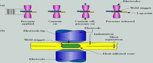
• A typical resistance welding cycle consists of (1) squeeze (2) weld and (3) hold period
• The resistance welding processes include spot welding, seam welding, roll spot welding, projection welding, upset welding, flash welding and percussion welding.
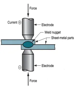
- Practically all metals can be resistance welded and the operation is quite fast.
- Weld nugget is generated by this process
- RW uses no shielding gases, flux, or filler metal.
- electrodes that conduct electrical power to the process are non-consumable
Current : 5000 to 20,000 A
Voltage : < 10V
Duration of current : 0.1 to 0.4 s (in spot-welding operation)
- Resistance in the welding circuit is the sum of (1) resistance of the electrodes, (2) resistances of the sheet parts, (3) contact resistances between electrodes and sheets.
- Resistance at the welding surfaces depends on surface finish, cleanliness, contact area, force. No paint, oil, dirt, and other contaminants should be present to separate the contacting surfaces.
- Advantages: no filler rod required, high production rates, automation and mechanization are possible.
- disadvantages: restricted to lap joint, costly equipment
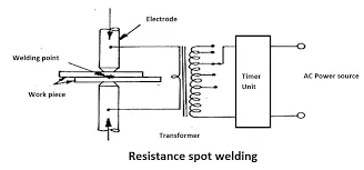
Resistance spot welding
Importance: a typical car body has got app. 15, 000 spot welds.
In this process, the fusion of electrodes is done by electrodes having opposing charges at one location. The sheet thickness has to be less than 3 mm for a good spot weld. The shape of electrode tip is important like round, hexagonal, square etc. The nugget shape will be app. 5-10 mm in this case. Electrodes in RSW: (i) Copper based, (ii) Refractory metal (Cu, Tungsten combinations).
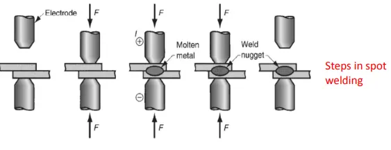
• This is the simplest form of resistance welding and does not possesses any
problem for welding sheets ranging up to 12.5 mm in thickness.
• For best results the surfaces to be welded must be free from scales and foreign
matter.
• Spot welding machines are available in three different types : stationary singlespot, portable single spot and multiple spot welding machines.
• Stationary single spot machines can be further classified into rocker arm type
and direct pressure type.
Seam Welding :
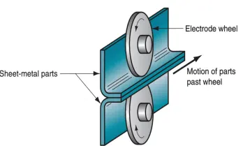
• In principle, seam welding is similarto spot welding except that it uses discshaped electrodes asshown in fig.
• Unlike spot welding the disc shaped electrodes are not separated after each weld but maintain a continuous pressure over the work pieces.
• Two common types of seam weld are Lap seam welding and Butt seam welding.
• The electrode current is timed to flow in pulses so that a row of welds is produced along the interface.
Gas welding / Oxyfuel gas welding
-In this process, various fuels are mixed with oxygen and burnt to perform welding. Eg: Oxyacetylene welding
Oxyacetylene welding (OAW):
In this case, welding is performed by a flame formed by the combustion of oxygen and acetylene. The flame comes from a torch.
A filler rod coated with flux is used sometimes which prevents oxidation, creating a better joint.
Acetylene is a famous fuel because it is capable of generating a temperature of 3500°C.
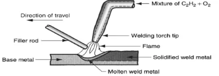
The chemical reaction between oxygen and acetylene happens at two stages as given below.
C2H2+ O2 = 2CO + H2+ HEAT (First stage; inner core)
The products of first reaction are combustible and second reaction occurs as, 2CO + H2 + 1.5O2 = 2CO2 + H2O + Heat (second stage; outer envelope)
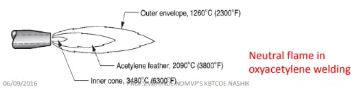
When both oxygen and acetylene are mixed in ratio of 1:1, then neutral flame is seen as shown in figure. The outer envelope delivers a temperature of 1260°C and inner core has app. 3500°C. The first stage reaction is seen as the inner cone of the flame (bright white colour), while the second stage reaction is seen in the outer envelope (colorless but with tinges ranging from blue to orange). The temperature is very high at the inner core which is app. 3500°C.
Total heat liberated during the two stages of combustion is 55×106 J/m3 of acetylene. But the heat transfer factor in OAW is 0.1 to 0.3 as the flame spreads over large region.
Problems and advantages of OAW:
• The combination of acetylene and oxygen is highly flammable and hence hazardous to environment.
• It is unstable at pressures much above 1 atm
• It is mandatory for the welder to wear gloves, goggles etc. as preventive measures.
• The equipment is relatively cheap and portable. So it is used as an economical, versatile process that is well suited for low quantity production and repair jobs.
• It is rarely used to weld plates thicker than 6.5 mm.
3.What is Resistance Welding & its application in the automotive sector?
Resistance welding is the joining of metals by applying pressure and passing current for a length of time through the metal area which is to be joined. The key advantage of resistance welding is that no other materials are needed to create the bond, which makes this process extremely cost effective.
There are several different forms of resistance welding (e.g. spot and seam, projection, flash, and upset welding) which differ primarily by the types and shapes of weld electrodes that are used to apply the pressure and conduct the current. The electrodes, typically manufactured from copper based alloys due to superior conductive properties, are cooled by water flowing through cavities inside the electrode and the other conductive tooling of the resistance welding machine.
Resistance welding machines are designed and built for a wide range of automotive, aerospace and industrial applications. Through automation, the action of these machines is highly controlled and repeatable allowing manufacturers to staff production readily.
Types of Resistance Welding Applications:
-
Spot Welding and Seam Welding
- Resistance Spot Welding, like all Resistance Welding Processes, creates welds using heat generated by resistance to the flow of welding current between the faying surfaces, as well as force to push the workpieces together, applied over a defined period of time. Resistance Spot Welding uses the face geometries of the welding electrodes themselves to focus the welding current at the desired weld location, as well as to apply force to the workpieces. Once sufficient resistance is generated, the materials set down and combine, and a weld nugget is rmed.
- Resistance Seam Welding is a subset of Resistance Spot Welding using wheel-shaped electrodes to deliver force and welding current to the parts. The difference is that the workpiece rolls between the wheel-shaped electrodes while weld current is applied. Depending on the particular weld current and weld time settings, the welds created may be overlapping, forming a complete welded seam, or may simply be individual spot welds at defined intervals.
-
Projection Welding
- Like other Resistance Welding Processes, Projection Welding uses heat generated by resistance to the flow of welding current, as well as force to push the workpieces together, applied over a defined period of time. Projection Welding localizes the welds at predetermined points by using projections, embossments or intersections, all of which focus heat generation at the point of contact. Once the weld current generates sufficient resistance at the point of contact, the projections collapse, forming the weld nugget.
- Solid Projections are often used when welding fasteners to parts. Embossments are often used when joining sheet or plate material. An example of Projection Welding using material Intersections is cross-wire welding. In this case the intersection of the wires themselves localizes heat generation, and therefore resistance. The wires set-down into one another, forming a weld nugget in the process.
-
Flash Welding
- Like other Resistance Welding Processes, Flash Welding uses heat generated by resistance to the flow of welding current, as well as force to push the workpieces together, applied over a defined period of time. Flash Welding is a Resistance Welding Process which generates resistance using flashing action. This action is created using very high current density at very small contact points between the workpieces. At a predetermined point after the flashing process has begun, force is applied to the workpiece, and they are moved together at a controlled rate. Rapid upset created by this force expels oxides and impurities from the weld.
-
Upset Welding
- Like other Resistance Welding Processes, Upset Welding uses heat generated by resistance to the flow of welding current, as well as force to push the workpieces together, applied over a defined period of time. While similar to Flash Welding, in Upset Welding the workpieces are already in firm contact with one another, so no flashing occurs. Pressure is applied before the current is started, and is maintained until the process is complete.
Applications:-
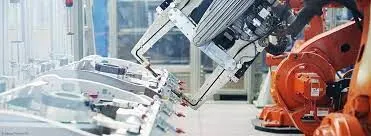
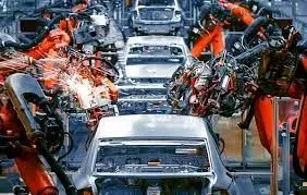
In an effort to reduce vehicle mass, automakers are incorporating lightweight materials within vehicle bodies at an ever increasing rate. The primary focus has been on incorporating ultra-high strength steels such as press hardened steels, complex phase steels, and others. Even further mass reductions can be achieved by incorporating aluminum alloy materials such as sheet, extrusions, and castings into a multi-material body. These lightweight materials must be joined to form automotive body structures in such a way to reduce mass, yet the ideal joint is a compromise between robust performance and an easily implemented production solution that is low-cost and high quality. Typical body structure assembly plants are based upon resistance spot welding technology as it is flexible, low-cost, fast, and can be applied to both aluminum-aluminum and steel-steel joints. However, resistance spot welding offers several interesting metallurgical challenges that must be addressed to form robust joints as advanced material alloys and combinations such as aluminum-steel are introduced. An introduction to joining in the automotive industry will be given with special emphasis on the metallurgy of resistance spot welding and the aluminum-steel spot welding process. Case studies will be presented that describe the static and dynamic mechanical performance of the dissimilar aluminum-steel welds and their robustness to production conditions such as gaps between sheets, electrodes off normal (at an angle) to the metal sheets, and changes in current.
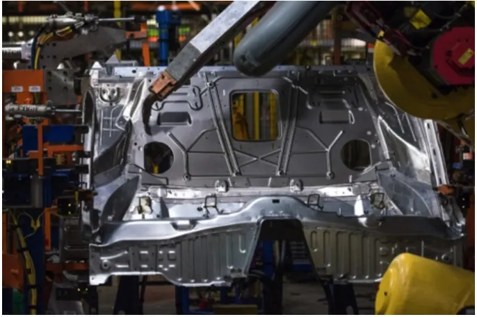
4. What is fusion welding and types of fusion welding with its application in the automotive sector?
Fusion welding
- In this type of welding the metal at the joint is heated to the molten state and it is allowed to solidify.
- Filler material may be needed for some kind of metal joints.
- It is classified as -
- Thermit welding
- Arc welding
- Gas welding.
1. Thermit welding:
- It is welding of parts by using liquid thermit steel around the portions to be welded. Since its a fusion welding process, neither arc is produced to heat the parts nor flames are used. For getting high temperature the exothermic reaction is used.
- Welding principle is the heat of the thermit reaction used for welding in plastic states and mechanical pressure is applied for the joint.
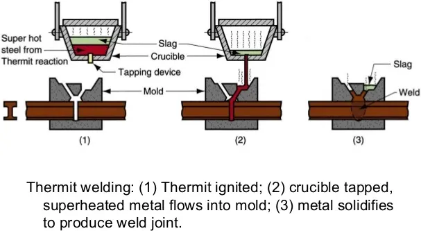
2. Arc welding:
- In arc welding process heat is developed by an electric arc. The electric arc is produced between the electrode and the workpiece.
- It is a process of joining 2 metal pieces by melting their edges by an electric arc.
- In arc welding electrical energy is converted into heat energy.
- The gap between the electrode and the workpiece is maintained at 3mm approx. Then current is supplied which produces the electric arc.
- The workpiece and the electrode is melted and both the parts will become a single piece without applying any external pressure.
- The temperature of arc is about 5000°C to 6000°C.
- A filler material is introduced during the welding which deposits along the weld bed.
- The depth to which the metal is melted and deposited is called the depth of fusion. To obtain a better depth of fusion, the electrode is kept at an inclination of 70° to the vertical.
- Types of arc welding:
- Manual Metal Arc Welding
- MIG
- TIG
- Submerged Arc Welding
- Plasma Arc Welding
- Atomic Hydrogen Arc Welding
- Carbon Arc Welding
- Eletroslag Welding
a. Manual Metal Arc Welding/ Shielded Metal Arc Welding:
Fig shows: Shielded Metal Arc Welding (SMAW)
- Manual Metal Arc Welding (MMAW/MMA) also known as Shielded Metal Arc Welding (SMAW) and informally known as stick welding.
- Stick welding is a process where the arc is struck between the metal rod (electrode flux coated) and the workpiece, both the rod and the workpiece melts to form the weld.
- An electric current either AC/DC is used as electric power supply.
- That power supply is used to form an electric arc between the electrode and the workpieces.
- The workpiece and electrode melts to form a molten pool which solidifies then to form the joint.
- As the weld is laid, the flux coating of the electrode provides the shielding gas as a layer of slag. These protects the weld area from atmospheric contamination.
- It is used in the joining of base parts of chasis and doors of the automobiles.
b. MIG welding:
- MIG welding - Metal Inert Gas welding.
- It is an arc welding technique in which a consumable electrode is used to weld 2 or more workpieces.
- It makes use of following components:
- Consumable electrode
- Inert gas supply
- Welding head
- AC/DC power supply
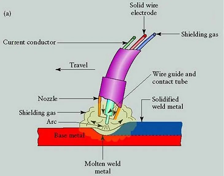
Fig shows: MIG welding
- It is also known as Gas Metal Arc Welding or Metal Active Gas Welding.
- The process can be semi-automatic or automatic.
- A constant voltage, DC power source is mostly used with GMAW, but constant curent systems as well as AC, can be used.
- There are 4 primary methods of metal transfer in GMAW, namely globular, short-circuiting, spray and pulsed spray each of which has distinct properties and corresponding advantages and limitations.
- This welding is used in the joining of bone, chassis area and engine part in automotive industry.
c. TIG:
- TIG - Tungsten Inert Gas Welding.
- It is an arc welding technique that uses a non-consumeable electrode tungsten electrode to weld 2 or more workpieces.
- The following components are required to perform TIG welding. They are:
- Power supply
- Non-consumeable tungsten electrodes
- Inert gas supply
- Filler rod(depends on nature of workpiece)
- Welding head
Fig shows: TIG welding
- An inert shielding gas is used to protect from oxidation or other atmospheric contamination.
- A constant current welding power supply produces electrical energy, which is conducted across the arc through a column of highly ionized gas and metal vapors known as plasma.
- TIG welding is most commonly used to weld thin sections of stainless steel and non-ferrous metals such as aluminium BIW structures of automobile.
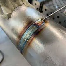
Fig shows: Application of TIG welding
3. Gas welding:
- Gas welding is one type of welding process in which the edges of the metals to be welded are melted by using a gas flame.
- NO pressure is applied during welding except pressure gas welding.
- The flame is produced at the tip of the welding torch.
- The gases commonly used are acetylene, hydrogen,propane and butane.
- It is used to weld the metal parts with thickness at the range of 2mm to 50mm.
- There are 3 types of welding processes that are employed in industries,
- Oxy-acetylene welding
- Oxy-hydrogen welding
- Air-acetylene welding
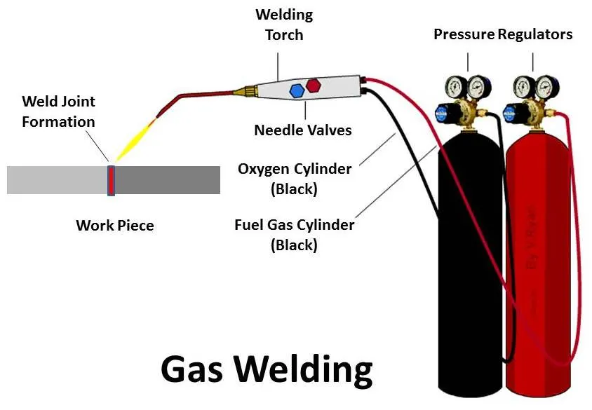
Fig shows: Gas Welding setup
- The most commonly used welding is the Oxyacetylene welding.
- Oxyacetylene welding- In this welding, the heat is obtained by burning a mixture of oxygen and combustible gases. The gases are mixed in the required proportion in a welding torch which provides the control of the welding flame.
- The flame only will melt the metal and a filler rod is used to fill the gap.
- Flux is used to prevent oxidation and to remove impurities.
- The temperature at the hottest region is about 3200°C.
- The cost of acetylene is low. The gases O2, C2&H2 can be stored at high pressure in separate tanks. But the acetylene is vey harmful if it is not handled carefully.
- There are two systems like High pressure system and low pressure system.
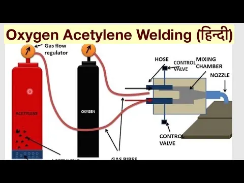
Fig shows : Oxyacetylene welding
5.What is the 3-2-1 principle?
A fundamental concern in metalworking is locating the part to be machined, punched, bent, or stamped relative to the work platform (fixture). For example, a CNC machine tool starts its process at a specific point relative to the fixture and proceeds from there. Hence, the accuracy with which a part is machined is quite dependent on the accuracy with which it is positioned in the fixture.
Accurate locating of not just one part, but each and every part that is loaded into the fixture is crucial. Any variation in part location on the fixture adds to the dimensional tolerance that must be assigned to the finished parts.
Additionally, the method of supporting and securing the part in the fixture affects not only dimensional tolerances, but surface finishes as well. This is true because improper supporting or clamping can temporarily or permanently deform the part. Hence, techniques for supporting and clamping must be considered together with the method of locating in order to assure repeatability from part-to-part.
Locating of a part to be machined is a three-step process:
1. Supporting
2. Locating (positioning)
3. Holding (clamping)
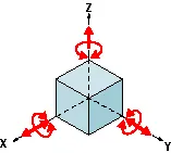
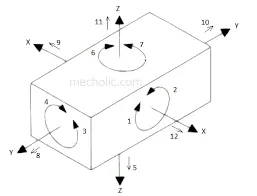
The Locating Process: Degrees of Freedom
In order to completely specify the position in space of a three-dimensional
object (such as the cube that’s shown), we refer to six coordinates:
- Translational position along the X-axis
- Translational position along the Y-axis
- Translational position along the Z-axis
- Rotational position about the X-axis
- Rotational position about the Y-axis
- Rotational position about the Z-axis
These six coordinates are known as the six degrees of freedom of a three-dimensional object. As the double-headed arrows indicate, the translational and rotational positions can vary in either direction with respect to each of the three axes.
To completely prevent movement, all six degrees of freedom must be restricted.
The Locating Process: 3-2-1 Method
We have two objectives when mounting a part in a fixture for machining:
1. Accurately position the part at the desired coordinates.
2. Restrict all six degrees of freedom so that the part cannot move.
A widely used method of accomplishing these two objectives uses the 3-2-1 principle, so-called because it entails three steps that employ three, then two, then one fixed points of known location. Since that adds up to six fixed points, it’s also known as the six point method.
In the three steps of the 3-2-1 method, three mutually perpendicular planes, called datum planes, are introduced, one at each step. These three planes define the workpiece position, and together with opposing clamping forces fully constrain the part. Let’s take a look at the details of the 3-2-1 method.
First Plane
Geometry tells us that three points are required to define a plane. This is the "3" in 3-2-1. So, three specific points are used to define the first plane. Fewer than three points cannot define a plane, and in the real world dimensional tolerances mean that four or more points will not be coplanar. A real-world, less than ideally perfect part placed on four or more reference points will, in fact, rest on only three of the points due to its less than perfect surface. Different parts may rest on different combinations of three points, resulting in variation between finished parts. A stool can be used to illustrate this concept. A two-legged stool would certainly be unstable. A three-legged stool sits rock-solid. A four-legged stool is often found to rock. In the illustration, a three dimensional part, represented by a cube, is placed on a datum plane defined by three support points. The part’s six degrees of freedom have now been reduced to three. It can still move along the X or Y axes, and it can still be rotated about the Z axis. (The part cannot move along the Z axis because it is held against the plane by clamping force.
Second Plane
A second plane, if it is perpendicular to the first, can be defined by two points, the "2" in 3-2-1. The part is now constrained to one degree of freedom: movement along the Y axis. (The part cannot move along the X or Z axes because it is held against the planes by clamping force.)
Third Plane
A third plane, if it is perpendicular to both of the first two planes, can be defined by one point, the "1" in 3-2-1. The part is now entirely constrained. It cannot move along or rotate about the X, Y, or Z axes. (Remember that the part is held against each of the three planes by clamping force.)
Repeatability
Repeatability is a paramount concern. It means that each part should be nearly identical to each other part coming off the same fixture. "Nearly identical" actually has a specific, quantifiable meaning: key dimensions of all parts produced on the same fixture must fall within defined tolerances.
In order to stay within tolerances, it’s best if the workpiece surfaces intended to contact the support points are machined. Cast surfaces are usable, but they tend to create tolerance problems. Machined holes are the number one choice, because two machined holes can be used to eliminate all but one degree of freedom.
The next best feature to use for consistent locating is machined surfaces at right angles. The "machined surface" desired here can simply be a tab or small flat specifically included for locating purposes.
Repeatability is achieved through application of the 3-2-1 method to the three aspects of the locating process:
1. Supporting
2. Locating (positioning)
3. Holding
Supporting
- The part is supported from "below" with reference to the Z axis. (Introduction of the first reference plane.)
- Gravity positions the part against the support locator.
- Provide adjustable auxiliary support points as needed to prevent deflection.
- Vertical location with respect to the fixture is now established
- The part is positioned horizontally, in the X-Y plane. (Introduction of the second and third reference planes.)
Holding
- The part is clamped against fixed locators. Therefore, a known and unvarying position of the part is maintained with respect to the X, Y, and Z axes.
- One strap clamp or clamp arm will restrict the workpiece in three dimensions due to friction between the workpiece and clamp. However, friction alone may not be enough to prevent the workpiece from moving during machining.
- Cutting forces will not move a properly supported and clamped part.
Locating
- The part is positioned horizontally, in the X-Y plane. (Introduction of the second and third reference planes).
Summary: Clamping Rules of Thumb
- Define three reference planes on the workpiece and fixture.
- Provide one opposing clamping force opposite each plane to restrict movement.
- When in doubt, rely on additional cylinders to take up uncertainty.
6.Define Body coordinate system?
BODY COORDINATE SYSTEM
- The body coordinate system is widely used in the automotive industry for drawing of body parts, products and process design.
- A coordinate system is a reference system consisting of a set of points,lines and surfaces,used to define the positions of points in space in either two or three dimensions.
- In general BCS is also called as car line and body line.
- Maintaining X, Y & Z coordinates in fixture is a very important factor. We should try that the co-ordinates of locating and clamping points should not be in three decimal. (e.g.X=100.124, Y=245.127, Z=450.458)
- They should be whole nos. or maximum upto 1 decimal. Once these co-ordinates are maintained automatically the BIW base structure is maintained.
X = Longitudinal direction[(Fore and After- F/A) or (Front O Line- FOL)]
Y = Transverse direction[(Cross car- C/C) or (Centre O Line- COL)]
Z = Vertical direction[(Up and Down- U/D) or (Bottom O Line- BOL)
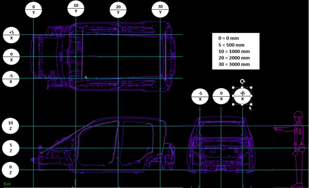
X(width of BIW) - OX is Body Center Line
Y(length of BIW) - OY is Near Front Bumper
Z(Height of BIW) - OZ is about Center of Wheel
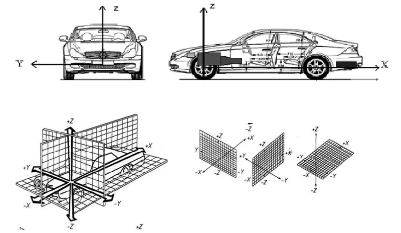
- The above schematic figure shows the basic car geometry system used widely to specify the position of parts which is to be assembled to the car body. From the first part of the production line this coordinate system is used to specify its position.
- According to the CAD data some references are specified to the car body on the basis of which each and every part of the car body is assembled respectively.
- The fixture position is also defined with reference of these coordinate system. The fixture is installed on the basis of these reference point defined by CAD data according to which the fixture base plate and the accessories are installed..
- Each and every parts measurement is done with reference to this coordinate system. The deviation in the assembly of car body and the components is shown with respect to these coordinates. An individual part measurement is also done with respect to these coordinate system.
- Accuracy of the BIW is also defined by the final measurement report which are based on these coordinate system.
7. Elaborate Body Plane System & its essentials.
BODY PLANE SYSTEM
- Body planes are reference planes in an automotive car. These planes are used to define the GD&T of all parts in an automotive domain.
- Body planes are 3 mutually perpendicular imaginary planes.
- The measurement from body plane to parts are called body plane dimensions.
- The planes are generally considered to be present in the driver position or sometimes at engine location or at the front end of the car depending on the customer.
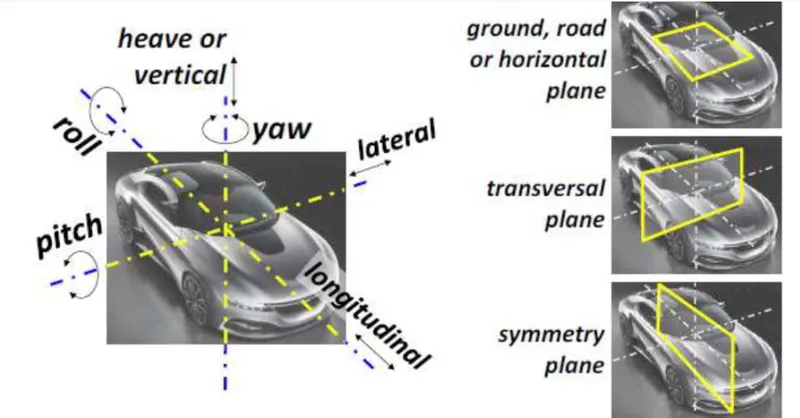
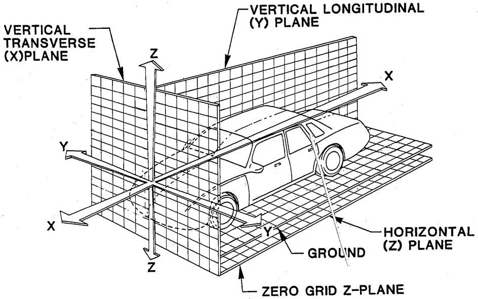
- The measurement from the body planes to the parts are called the body line dimensions.
X = Longitudinal direction[(Fore and After- F/A) or (Front O Line- FOL)]
Y = Transverse direction[(Cross car- C/C) or (Centre O Line- COL)]
Z = Vertical direction[(Up and Down- U/D) or (Bottom O Line- BOL)
Fig shows: Typical body plane of a car
Body line dimensions are essentials for the following reasons:
- It defines exact position of each product in the vehicle with respect to a fixed origin.
- It ensures flawless design for assembly.
- While designing lines, all the designs are carried out relative to the bodylines viz.fixtures,turntables,etc.,
- It assists in easy location of different parts in the vehicle.
- It aims in creating a standardized system.
- It assists in quality check.