Week 2:- BiW Fixture Basics Challenge
Week 2:- BiW Fixture Basics Challenge
1) What is the process of project execution activity?
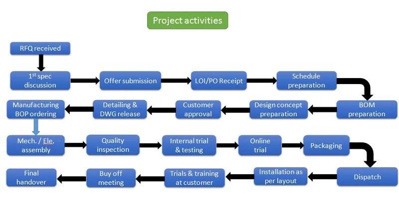
* RFQ - This RFQ is nothing but Request For Quotation. In this stage customer requests
technical and as well as commercial offer along with design data, some old reference
in some cases.
* 1st Spec discussion - This discussion happens between manufacturer and customer regarding
the project based on customer submitted data. in this most of the doubts
are clarified by the customer regarding design, dimensions, accuracy
and many more. And here generally we discuss time for project completion
and some technical things.
* LOI/PO receipt - LOI stand for Letter Of Intent and PO is for Purchase Order. PO is released by customer
it ensure that technical and commercial offer has been accepted.
* Schedule preparation - In this stage manufacturer have submit his schedule for design, Manufacturing,
quality assurance, Testing, commissioning, trials and for other things.
* BOM preparation - BOM stands for Bill Of material, in this manufacturer have prepare details of
all parts material and quantity which are using for particular fixture like, gripper,
actuators, pins, blades raisers, hardware’s and etc.
*Design concept preparation - In this manufacturer have to submit the design concept as per
customer requirement. With respect to customer data and old discussion.
* Customer approval - What we designed earlier we have to submit for approval to customer.
If any suggestions are from customer we have to add or remove from our
current design.
* Detailing and drawing releasing - If customer agree for design, we have to prepare detail drawing for
various manufacturing methods (DFM - design for manufacturing) like
for milling, turning, laser cut, wire cut and etc. with respect to
method of manufacturing.
* Manufacturing BOP ordering - In this stage we order some equipments like cylinder, actuators, grippers and etc.
* Mechanical or Electrical assembly - In this stage assembly team will assemble all the stations as per
released drawing and layout.
* Quality inspection - after assembling QC team have to check as per released drawing and
also as per customer requirement.
Quality team have ensure all used material and equipment quality also.
* Internal trial and testing - In this stage we have to take trials inhouse, either this fixture working
good or not.
* Online trial - Online trial involves checking all the sequences, all operational equipment’s and taking
actual production to achive cycle time. And manufacturer have submitted trial data to customer
for approval.
* Packing - Customer will approve fixture after reviewing then we have to make proper packing as per
standards. with respect to mode of transport either by road, air or sea.
* Dispatch - dispatch fixture by better mode of trnsport either by road, air or sea.
* Installation as per layout - Manufacturer have to install of fixture at pre-decided layout. all assembly
have to be done as per drawing, with respect to other robots, other assembly
units and all.
* Trials and training at customer - After installation have to take trials and we have achive cycle time
as peras quality. and also we have to give training to their engineers
how this fixture works, what are the sequences and all.
* Buy off meeting - This meeting is between customer and manufacturer, in this customer will check each
and everything either it is as per PO or not. in some cases customer may be ask for
small corrections or development that will cost extra.
* Final handover - after buy off meeting and correctin minor things, manufacturer have to handover the project
to customer along with manuals, maintenance documents, SOP document and etc.
This is project execution activity.
2) What are the types of joining processes?
There are mainly two types of joining process
1) Metallurgical joining.
2) Mechanical joining.
Metallurgical joining
Joining includes welding, brazing, soldering, adhesive bonding of materials.
They produce permanent joint between the parts to be assembled.
a) Welding
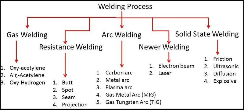
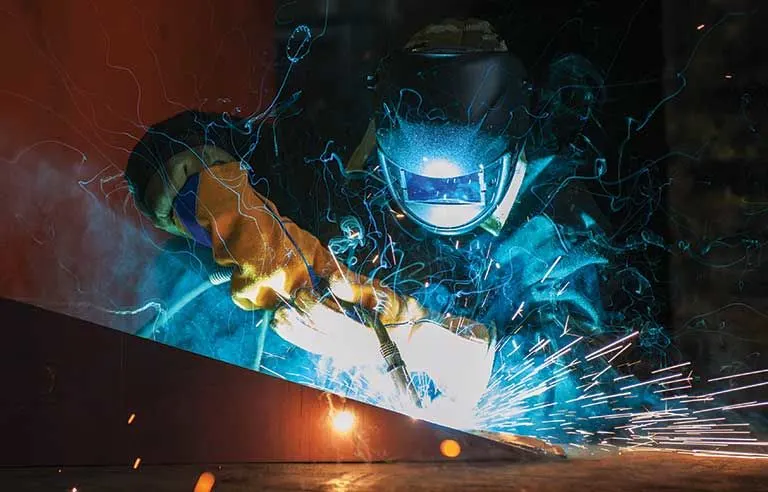
Welding is a process by which metals are joined by heating them to a suitable temperature
with or without the application of pressure and addition of filler materials. Welding processes are
employed in most of the modern fabrication works and industries.
Some times, welding is done just by applying heat alone, with no pressure applied
In some cases, both heat and pressure are applied; and in other cases only pressure is
applied, without any external heat. In some welding processes a filler material is
added to facilitate coalescence(Joining)
b) Brazing
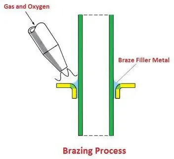
Brazing is a method of joining two pieces of metal together with a third, molten filler metal.
Of all the methods available for metal joining, brazing may be the most versatile.
The process is relatively fast and economical, requires relatively low temperatures and is
highly adaptable to automation and lean manufacturing initiatives.
Brazed joints have great tensile strength – they are often stronger than the two metals
being bonded together. Brazed joints repel gas and liquid, withstand vibration and shock
and are unaffected by normal changes in temperature. Because the metals to be joined
are not themselves melted, they are not warped or otherwise distorted and retain their
original metallurgical characteristics.
Use this guide to learn about the different aspects of brazing and the many advantages
offered by this unique process.
c) Soldering
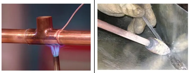
Soldering is a process used for joining metal parts to form a mechanical or
electrical bond. It typically uses a low melting point metal alloy (solder) which
is melted and applied to the metal parts to be joined and this bonds to the metal
parts and forms a connection when the solder solidifies. It is different to welding
in that the parts being joined are not melted and are usually not the same material
as the solder.
Soldering is a common practice for assembling electrical components and
wiring. Although it can be used for plumbing, sheet metal fabrication or
automotive radiator repair the techniques and materials used are different to
those used for electrical work. This document is intended to provide guidance
on the safe working methods and proper tools and techniques for soldering of
electrical components.
d) Adhesive bonding
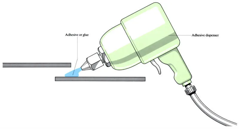
The increasing demand of lighter, fast, cheap and stronger joints require new joining
methods. In this manner resistant spot welding is a good option for fast, cheap and
lighter joints but strength of joints may or may not behigh because of such type of
welding which depends on the weldability rating of the working material. Weldability
rating of any metal depends on three factors namely
1) resistivity
2) melting temperature, and
3) thermal conductivity.
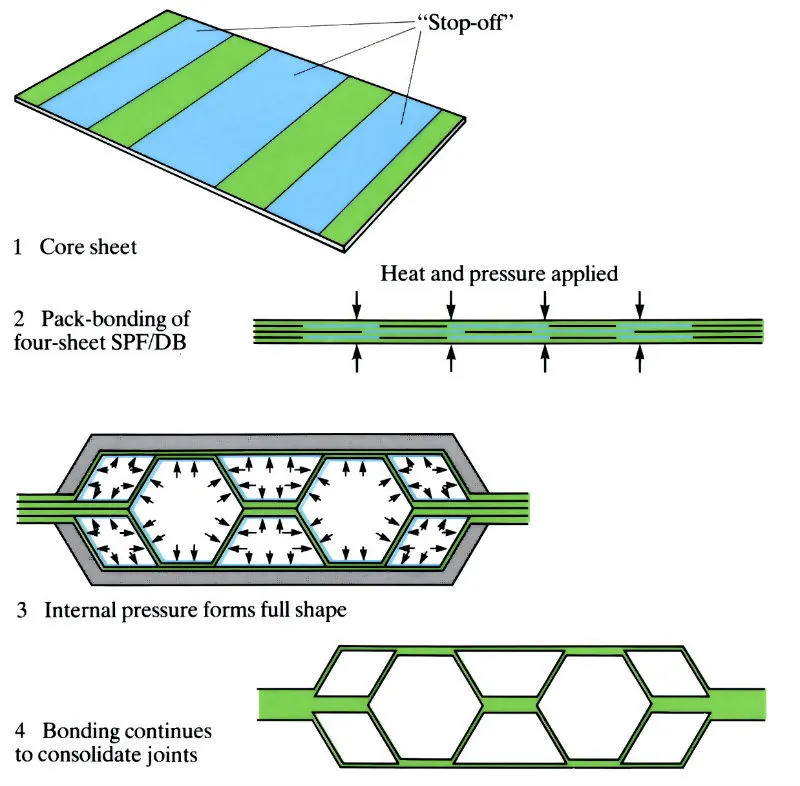
e) Diffusion bonding
The diffusion bonding process, that is, the application of pressure and temperature to an
interface for a prescribed period of time, is generally considered complete
when cavities fully close at the faying surfaces. Relative agreement is found
for the mechanisms and sequence of events that lead to the collapse of
interface voids, and the discussion below describes these metallurgical
processes. Although this theoretical understanding of the diffusion bonding process is
universally applicable, it should be understood that parent metal strength is
only approached for materials with surface conditions that do not have
barriers to impede atomic bonding such as the absence of surface oxides or
absorbed gases at the bonding interface.
Mechanical joining.
The Products which are not possible to manufacture as single piece are fabricated by
joining different parts. Examples of such products are steel furniture, computers and
automotives, transmission or sheet metal assemblys etc.
a) Mechanical fastening
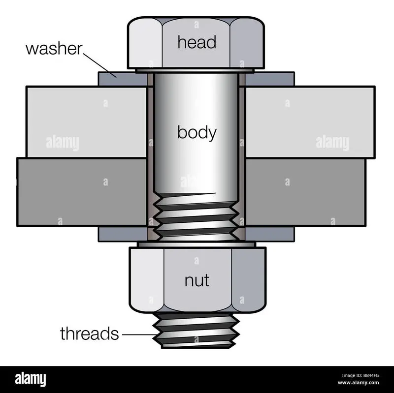
When using common mechanical methods for securing parts, pay special attention to the
fastener’s head. Conical heads, called flat heads, produce undesirable tensile stress in the
mating parts and should be avoided. Bolt or screw heads that have a flat underside,
called pan or round heads, produce less harmful, compressive stress.
Use flat washers under both nut and fastener heads, because these help
distribute the assembly force over larger areas.
b) Self piercing riveting
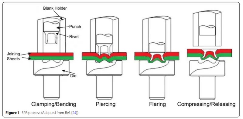
Self-piercing riveting is a cold forming technique used to fasten together two or more
sheets of materials with a rivet without the need to predrill a hole.
The application of self peircing riveting in the automotive sector has become increasingly popular
mainly due to the growing use of lightweight materials in transportation applications.
However, this joining of these advanced light materials remains a challenge
as these materials often lack a good combination of high strength and
ductility to resist the large plastic deformation induced by the self peircing riveting process.
c) Hemming and seaming
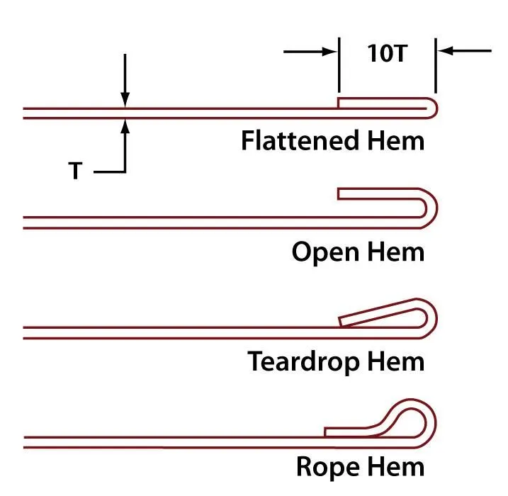
Hemming and seaming is one of the last operations to be used on auto body panels. Therefore, it has a critical
importance on the performance and perceived quality of assembled vehicles. Due to the
required precision on the hemming process and the complexity of the parts,
most of the bending, flanging and hemming dies are designed based on experience and on
lengthy and costly die tests. EMF can be a solution that saves time as well as money
and improves the quality of the hem joint, especially when using aluminum alloys
3) What is Resistance Welding & its application in the automotive sector?
Resistance Welding
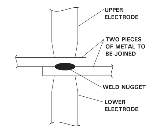
The two pieces of metal to be joined are squeezed together by the electrodes on the welding
machine so they are in good electrical contact. Then electric current is passed through them,
heating them until they begin to melt at the spot where they are in contact.
The molten metal from the two pieces flows together; then the current is turned
off and the molten metal solidifies, forming a solid metallic connection
between the two pieces. The term “Resistance Welding” comes from
the fact that it is the electrical property of resistance of the metal being
welded that causes heat to be generated when current flows through it.
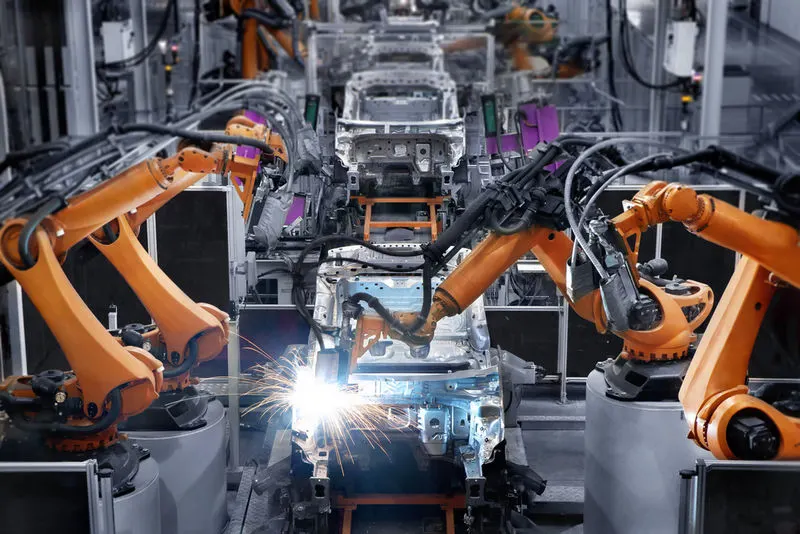
Resistance Welding application in the automotive sector
Resistance welding is an important process in the automotive industry. The
advantages of ths welding are many:
an economical process, adaptable to a wide variety of materials and thicknesses,
a process with short cycle times, and overall, a relatively robust process with some
tolerance to fit-up variations. Although used in mass production for several decades,
Resistance weding poses several major problems, most notably, large variation in weld
quality. To avoide variation and uncertainty in weld quality due to factors such as tip
wear, sheet metal surface issue, and etc. In recent years, global competition for
improved productivity and reduced nonvalue added activity, is forcing automotive
OEMs and others to eliminate rehection rate due to weld quality.In order to minimize
the number of spot welds and still satisfy essential factors such as strength and surface
integrity, weld quality has to be monitored and controlled in real-time.
4) What is fusion welding & types of fusion welding with its application in the automotive sector?
Fusion welding
Fusion welding is a process that uses heat to join or fuse two or more materials by heating
them to melting point. The process may or may not require the use a filler material.
Fusion welding processes can be grouped according to the source of the heat,
for example, electric arc, gas, electrical resistance and high energy. A filler
material is necessary if there are gaps in the joint you are making.
Fusion welding takes place when the molten base materials join with molten fillers.
The heat that melts the materials can be applied to the joining zone or developed
externally at the intended weld point. For instance, you can pass current via an
electrical contact resistance between the edges of the materials you are
welding together to develop the heat you need.
Types of fusion welding
1) Arc welding.
a) Manual metal arc welding.
b) Gas-shielded metal arc welding or metal inert gas welding or MIG.
c) Gas- shielded tungsten arc welding or TIG.
d) Plasma arc welding.
e) Submerged Arc Welding.
Arc welding
Arc welding is a fusion welding process in which welding is done by producing
heat from an electric arc between the work and electrode. Both D.C. and
A.C. electric supply are used for this. The arc between the two terminals
produces heat to melt the metal. If two pieces of metal that are to be joined
are placed so that they touch or almost touch one another and the arc from
the electrode is directed at this junction, the heat generated by the arc
causes a small section of the edges of both pieces to melt.
These molten portions along with the molten portions of the electrode flow together.
As the arc column is moved, the molten puddle solidifies joining the two
pieces of metal with a combinmation of electrode and base metal.
a) Manual metal arc welding.
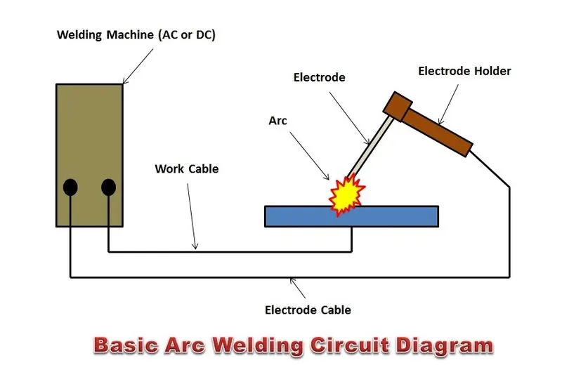
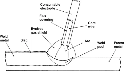
The commonly used arc welding method is manual metal arc welding. In this process a metal
electrode is used. The metal electrode itself melts and acts as a filler material. An arc
welding circuit consists of the following essential items
a) The power source ie the Welding machine
b) Welding lead cable and electrode holder
c) Welding return cable and clamp
d) Welding earth
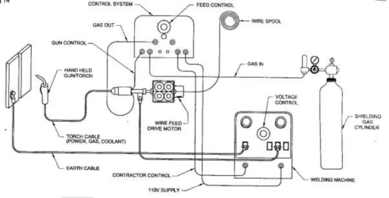
b) Gas-shielded metal arc welding or metal inert gas welding or MIG.
In this process the arc is formed between a continuous, automatically fed, metallic
consumable electrode and welding job in an atmosphere of inert gas, and hence this is
called metal inert gas arc welding (MIG) process.
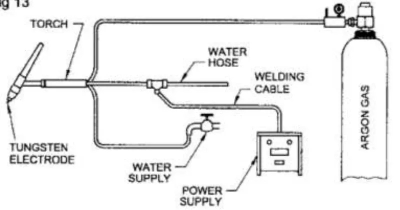
c) Gas- shielded tungsten arc welding or TIG.
In this process the arc is formed between the tungsten electrodes (nonconsumable)
and the welding job in an atmosphere of an inert gas (argon or helium).
Aseparate filler rod is used to add the filler metal. This process is also called gas
tungsten arc welding process.
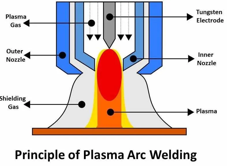
d) Plasma arc welding.
In this process the arc is formed between a tungsten electrode and the welding job in an
atmosphere of plasma-forming gasnitrogen, hydrogen and argon. A separate filler rod
is used to add the filler metal in the joint, if necessary. But normally no filler rod is used.
The process is similar to TIG welding Plasma cutting is used to cut non-ferrous
metals and alloys successfully and quickly.
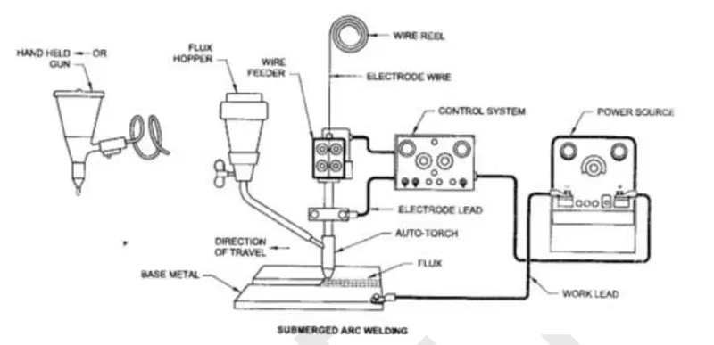
e) Submerged Arc Welding.
In this process the arc is formed between a continuous, automatically fed, metallic
consumable electrode and the welding job under a heap of powdered/ granulated flux.
The arc is totally submerged in the flux it is invisible.
Fusion welding applications in the automotive sector.
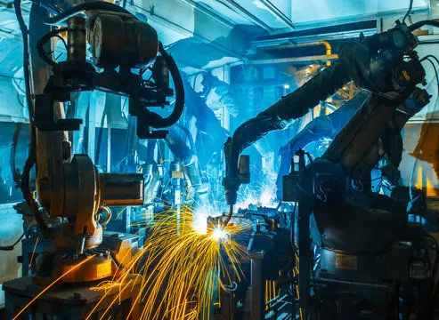
Fusion Welding method used in the automotive industry to must be able to achieve
high production rates, provide superior quality weldments, be easily mechanized
with short set-up times, have the flexibility to accommodate design changes
and maintain acceptable working environment standards. The current methods used in
the automotive industry to meet these requirements.
5) What is the 3-2-1 principle?
3-2-1 Locating Principle
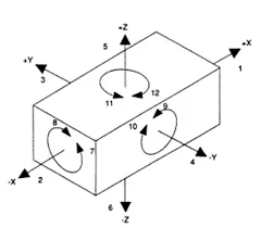
* A workpiece, just like any free solid body, has six degreesof freedom
some researchers have referred this to thetwelve degrees of freedom
by considering the +/-movements in each category
* For locating it is necessary to arrest all these six degreesof freedom
to ensure the mechanical stability.
* A single locator in Plane 1 would arrest the linear motionalong the X-axis.
* A second locator in the same plane would arrest therotary
motion about the Z-axis.
* Another locator placed in the same plane would arrestthe rotary
motion about the Y-axis.
* Adding one more locator in Plane 1 would not serve anypurpose.
* So fourth locator is placed in Plane 2 which isperpendicular to Plane 1.
This would restrict the linearmotion along the Y-axis.
* The fifth locator is placed in the Plane 2 which canarrest the rotational
motion about the X-axis.
* The sixth locator placed in Plane 2 would not serve anypurpose.
* So, sixth locator is placed in Plane 3 which isperpendicular both the
planes 1 and 2. This wouldarrest the linear motion along the Z-axis.
Considering 12 Degree Of Axis
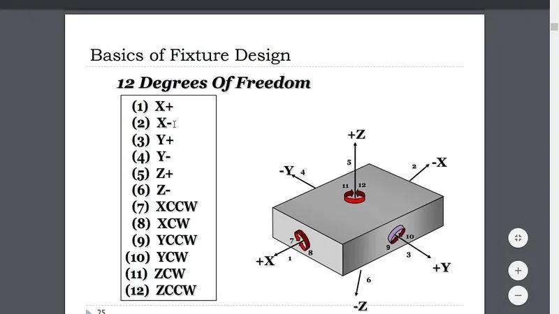
* We must fix all the 12 degrees of freedom except thethree transitional degrees
of freedom (-X, -Y and -Z) inorder to locate the work piece in the fixture.
So, 9 degreesof freedom of the work piece need to be fixed.
* Rest the work piece on three non-collinear points of thebottom surface (XY),
and you will be able to fixthe +Z, Clockwise Rotation-X, AnticlockwiseRotation-X,
C Rot-Y and AC Rot-Y degrees of freedom.
* Now, rest the work piece at two points of side surface(XZ), and you will be
able to fix the +Y and C Rot-ZandAC Rot-Z degrees of freedom.
* Now, rest the work piece at one point of the adjacentsurface (YZ),
and you will be able to fix the +Xdegrees offreedom.
6) Define Body coordinate system?
The body coordinate system has been widely used in the automotive industry
for drawing of body parts, product & process design. A coordinate system
is a reference system consisting of a set of points, lines & surfaces, used
to define the positions of points in space in either two or three dimensions.
In general BCS is also called as car line & body line.
Car lines are the (grid lines) shown on the fixture, which virtually
represent the same location in BIW. All the car line on fixture displays
the coordinate at corner for reference. With these lines one can
easily relate the location in BIW.
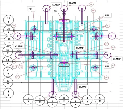
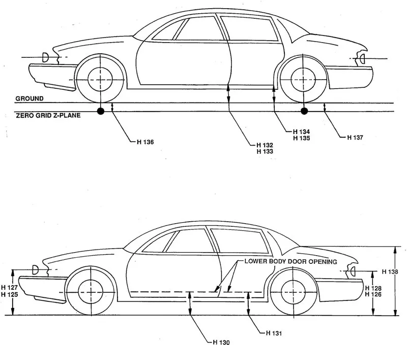
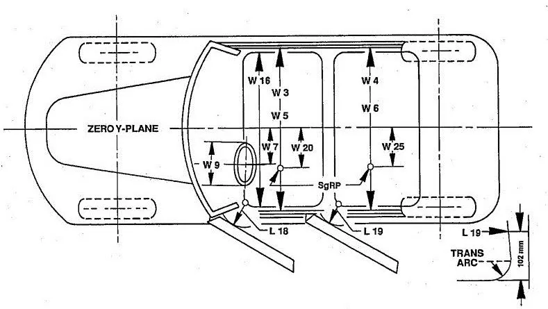
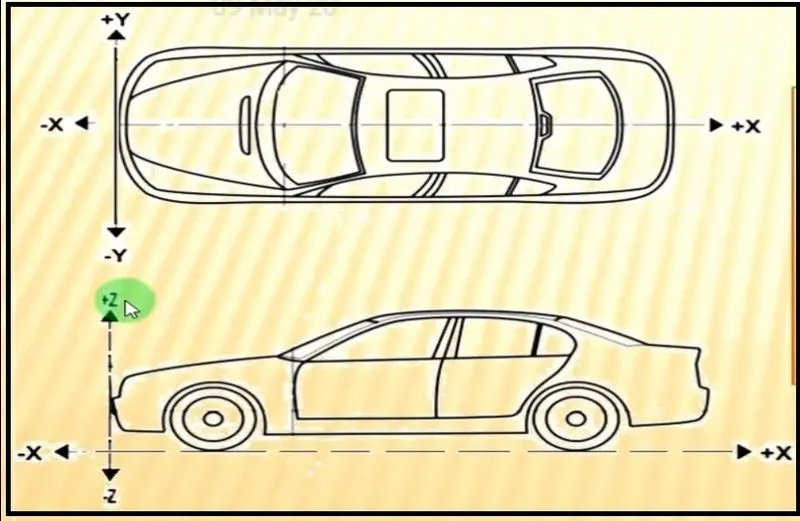
Vehical Orientation - All vehicle product drawings are identified numerically relative
to three vehicle planes described and shown below.
X= longitudinal direction (fore & after-F/A) or (Front O line-FOL).
Y= transverse direction (Cross car-C/C) or (Centre O line-COL).
Z= Vertical direction (Up & down- U/D) or (Bottom O Line-BOL).
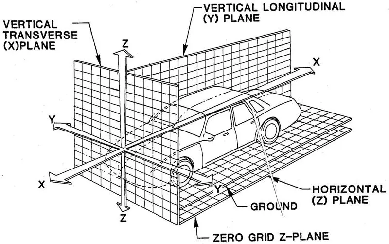
7) Elaborate Body plane system & its essentials.
* These are are three mutually perpendicular imaginary planes.
* These are used to define GD & T of all parts in automotive domain.
* The measurement from body plane to parts are called bodyplane dimensions.
Essentials.
* It defines the exact position of each product in the vehicle w.r.t. a fixed origin.
* It ensures flawless design for assembly.
* While designing lines, all the designs are carried out relative to the bodyline, viz, fixture, turn table etc.
* It assists in easy location of different parts in a vehicle.
* It aims in creating a standardized system.
* It assists in quality checks.