Week 2:- BiW Fixture Basics Challenge
project excution activity involved these process below
RFQ
in this step where customer gives the detail requirement and the spec reqired for the supplier in document form also customer specifies
its technical offer,Commercial Offer etc., How the project will be executed and the timeline of the project also will be mentioned.
KICK OFF MEETING
After first step we have to discuss with in our team about time required for the Data study,3D design concept,Simulation validation,Quality
check,2D Drawing release,Bought outs,manufaturing,Assembly,Installation and comissioning will be discussed and prepared in the technical offer.
OFFER SUBMISSION
After kick off meeting we will submit the quation for the with the customer end
PO RECEIPT
after offer submission customer will finalize the offer and custmomer will relese the PO(purchace oder).
SCHEDULE PREPARATION
after reciving the po from the customer we have to prepare schedule for the project complition with in the timeline
BOM PREPARATION (bill of material)
Bill of material like cylinders,motors etc.,Which is required for the project are prepared.
DAESIGN AND CONCEPT VALIDATION
in this step we will design the parts and the assembly with the concept disscused in the kick off meeting. inthis step also includes the avoiding the
clashes of clamping tools with pannel and weld guns.
CUSTOMER APPROVAL
after desing and concept validation .The customer will review the design concepts.f the design need to be made simple or some other correction
needs to be done in concept design will be discussed and after meeting the requirements of the customer,They will give approval to the design to
go on with further activities.
DETAILING AND DRAWING RELEASE.
after customer approval, we need to deatail the parts with required manufacturing dimensionand gd and t symbols
MANUFACTURING AND BUY OUT PARTS.
After deatailing the manufacturing parts are made and standared parts and buy out part should be ordered.
MECHANICAL ASSEMBLY AND ELECTRICAL ASSEMBLY
After the materials ordered received to our end.The quality will check the working conditions and technical specs.Which meets our reqirements.
QUALITY INSPECTION
After the assembly again the quality check is done.In all dimensions,positional accutancy,Coordinates are checked using CMM
INTERNAL TRAIL
It is a first trial taken inhouse,So we will see by putting the assembly in the fixture whether the seating of assembly/panel suited correctly.
Whether the clamping operation is done properly,Also whether the pins are getting into the holes etc
ONLINE TRAIL
The trail will be done in automatically made through the control panel.The process sequence of operation is checked as by the designed way.
PACKAGING
To avoid damage occur in fixtures while transportation which may also lead to affect the aesthetic look and proper fuction of fixture packaging has
been done.After the trails taken have to get the QC confirmation whether the panels met the standards/Specs. Given by the customer also whether
the fixture meets the customer standards.After approval of QC,Packaging is been done as per standards.Certain companies follow certain packaging
standards,So the packaging should be one as per customer standards.
DESPATCH
After the fixture has been packed for delivery as per standards.Its been despatched to the customer.
INSALLATION
As we discussed in design concept preparation,The design of the layout are been prepared at a very intial level which gives the information of
placements of robots and fixtures.According to the design the installation and commissioning team will install the fixtures.
TRAILS AT CUSTOMER END
Production trails will be taken at the customer end.During the technical offer,We will be confirmed that N number of assemblies will be produced
within 8hrs/12hrs shifts.So in customer trail,we have to achieve the confirmed quantity of assemblies.Once it is achieved,Training will be given to
the operator,staffs,engineers who involved in this process.The sequence of the working process by the fixture will be explaned in detail.The
checkpoints which have to be done after placing the panels into the fixture will be made clear to them.
BUY OFF MEETING
After trials and training at customers end,buyoff meeting will be held.In this meeting customer will give reviews about the fixtures,Sometimes a
customer may need/feels better to do some additional work also,It will be discussed and finalize in the meeting.
FINAL HAwR
The fixture and the documents suopport the fixtures/Production will be handed over.Documents like clamps validation document,Ergo
sheets,BOMs,Charts will be delivered abd handed over to customers.
2;
- The material being joined - similar or dissimilar, aluminum, iron, copper, etc.
- Type of assembly- Temporary or permanent.
- Economy.
- Service condition - load, temperature, etc.Generally the metal joining process means the welding process. According to the composition of the joint, they are classified into
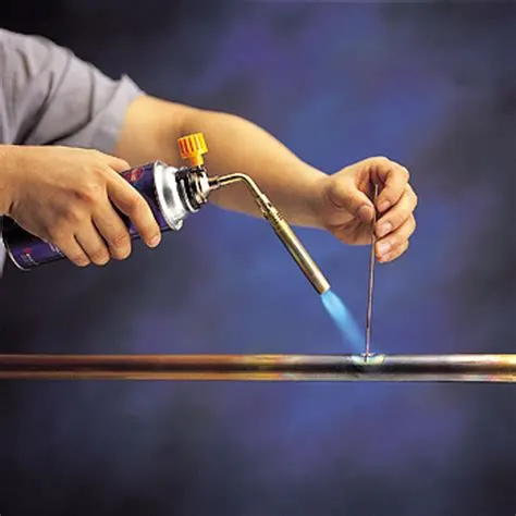
RESISTANCE SEAM WELDING
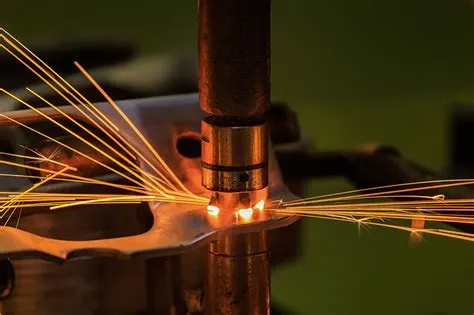
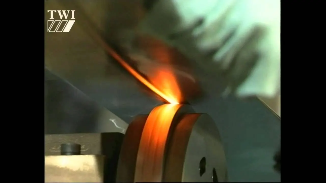
Resistance seam welding is a variation of the standard spot welding form, however instead of spot one nugget, a series of overlapping nuggets is
produced. This is usually done by replacing the conventional spot welding electrodes with wheels, which turn as the parts are fed between them.
The process thus produces a continuous welded seam rather than a single spot. Seam welding is often used in the production of thin sheet, leak-
tight containers such as fuel tanks, and is generally unsuitable for welding aluminium.
RESISTANCE PROJECTION WELDING
Resistance projection welding is a form of resistance welding where the electricity, force, and weld time are concentrated on raised ‘projections’
across the surface. Projection welding is generally used for welds using thicker materials than the thinner metal pieces that spot welding is usually
required for, and often not metals. It is used primarily in the electrical, automotive and construction industries.
4; FUSION WELDING
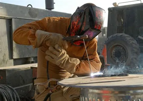
Fusion welding is a process that uses heat to join or fuse two or more materials by heating them to melting point. The process may or may not require the use a filler material. External application of pressure is not required for fusion welding processes.
types of fusion welding
TUNGSTEN INERT GAS WELDING
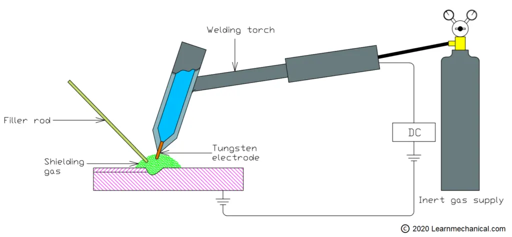
Tungsten inert gas welding uses non-consumable tungsten to create the arc between the electrode and the base plate. The TIG welders for aluminum use an inert shielding gas to prevent contamination and oxidation.
METAL GAS ARC WELDING
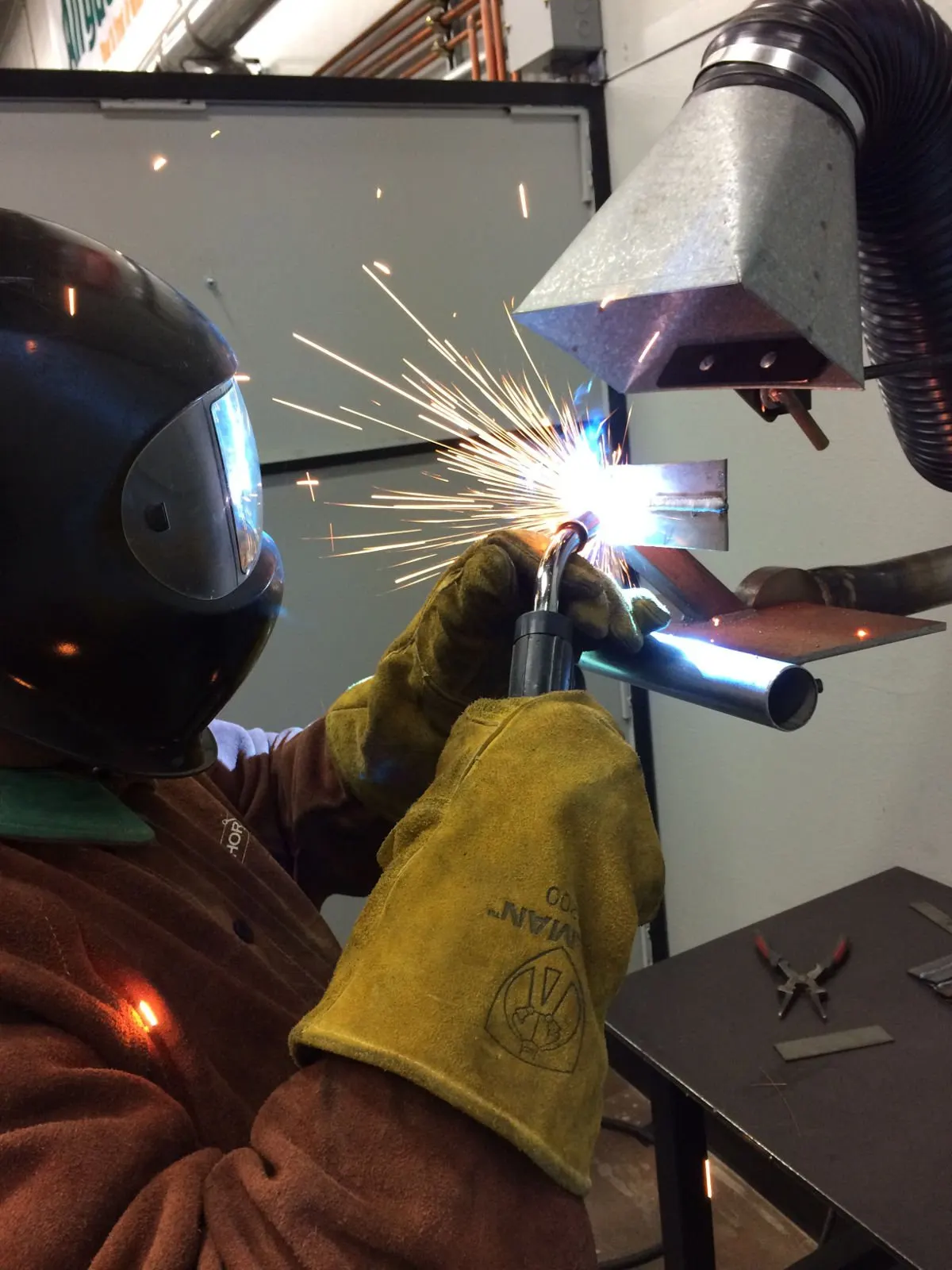
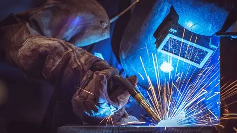
Metal gas arc welding involves the formation of an electric arc between the wire electrode and the material using the MIG welders. The use of shielding gas prevents contamination.
SUBMERGED ARC WELDING
Submerged arc welding is the method that involves using flux and a consumable electrode. The flux prevents the sparks and spatters and conducts electricity while in the molten state.
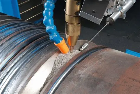
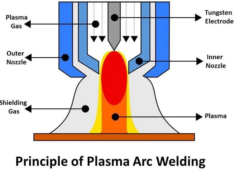
PLASMA ARC WELDING
Plasma arc welding involves the formation of an electric arc between the nozzle and the electrode. The electric arc ionizes the argon gas found in the chamber.
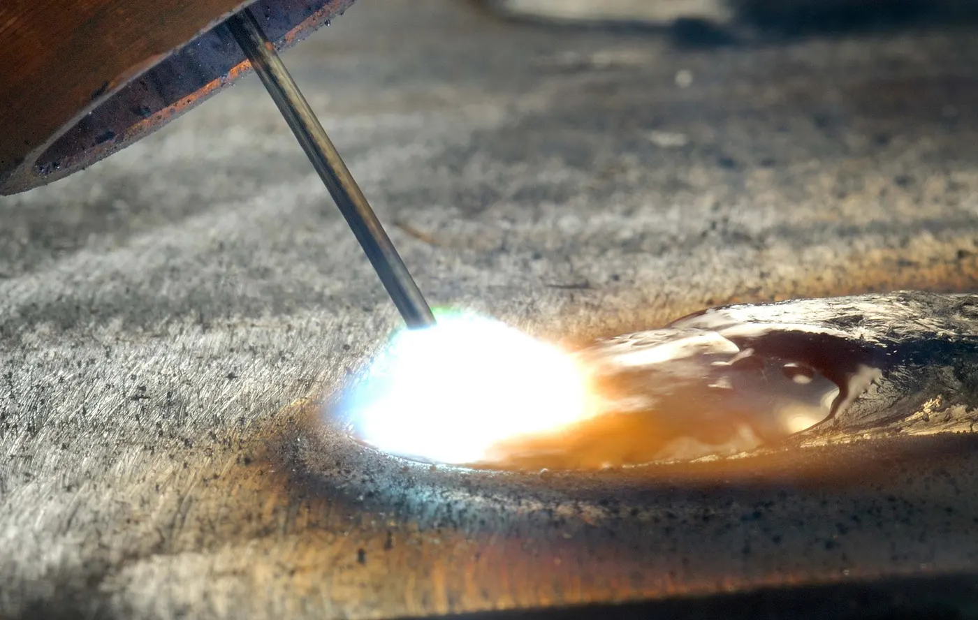
FLUX CORED ARC WELDING
Flux cored arc welding is an alternative to shielded Metal Arc Welding. The whole process involves feeding consumable electrodes with flux using the flux core welders for the thickest metals.
5:3-2-1 PRICIPLE
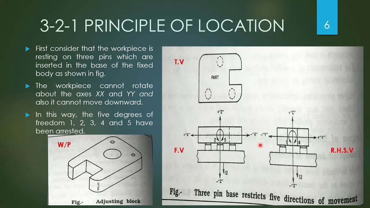
In this method, 9degrees of freedom is controlled.
Pins A, B, C on the base plane ( a plane parallel to the plane which contains X and Y axis) restrict the rotation of component about X axis and Y axis. It also limit the downward movement of component along z axis. Ie. 1,2,3,4 and 5 degrees of freedom is restricted.
Pins D, E is in plane parallel to the plane containing X and Z axes. It prevents the rotation of component about Z axis (6, 7 degree of freedom) and the movement of the body in along Y axis towards one direction (8 degree of freedom).
The last pin F is in a plane parallel to plane contains Y and Z axes. It restricts the movement component along X axis in one direction.
Three remaining degree of freedom 10, 11, 12 is unrestricted. It facilitates the loading of the component in the fixture. This three degree of freedom may restrict after loading of component by using clamping device
The body coordinate system has been widely used in the automotive industry for drawing of body parts,Products and process design.A coordinate
system is a reference system consisting of a set of points,lines and surfaces,used to define the positions of points in space in either two or three
dimensions.
X=Longitudinal direction [(Fore and After - F/A) or (Front O Line - FOL)]
Y=Transverse direction [(Cross car - C/C) or (Center O Line - COL)]
Z= Vertical Direction [(Up and Down - U/D) or (Bottom O Line - BOL)]
The origin of the body coordinate system (OX) is defined at the front center of a vehicle,It indicates a length of car and the coordinate system (OZ)
is below its underbody indicates height of car,and the coordinate system (OY) its starting point is the center of car body indicates width of car.
The above schematic figure shows the basic car geometry system used widely to specify the position of parts which is to be assembled to the car
body. From the first part of the production line this coordinate system is used to specify its position. According to the CAD data some references are
specified to the car body on the basis of which each and every part of the car body is assembled respectively.
The fixture position is also defined with reference of these coordinate system. The fixture is installed on the basis of these reference point defined
by CAD data according to which the fixture base plate and the accessories are installed. Each and every parts measurement is done with reference
to this coordinate system. The deviation in the assembly of car body and the components is shown with respect to these coordinates. An individual
part measurement is also done with respect to these coordinate system. Accuracy of the BIW is also defined by the final measurement report which
are based on these coordinate system.
7:BODY PLANE SYSTEM
Body planes are the reference planes in an automotive car.These planes are used to desfine the GD&T of all car parts in a automotive domain.
Body planes are 3 mutually perpendicular.Imaginary planes.These are genrally considered to be present at the driver position or sometimes at the
engine location or at the front end of the car,depending on the customer.
The measurement from the body planes to the parts are called as bodyline dimensions
These body planes are called as.
FOL Front O Line.
COL Centre O Line.
BOL Body O Line.
The measurement along FOL or X axis is called as F/A Front Aft.
The measurement along COL or Y axis is called as C/C Cross Car.
The measurement along BOL or Z axis is called as U/DUP DowN.
PLANE SYSTEM ESSENTIALS
It defines the exact position of each product in the vehicle w.r.t a fixed origin.
While designing lines,All the designs are carried out relative to the bodyline,Fixtures,Turn tables etc.
It assists in easy location of different parts in a vehicle.
It aims in creating a standardized system.