Week 2:- BiW Fixture Basics Challenge
1.
2.
Types of joining process:
- Metallurgical Joining
- Mechanical Joining
Types of welding: Welding processes can be broadly
classified into
(i) fusion welding, and (ii) solid-state welding
Fusion welding:
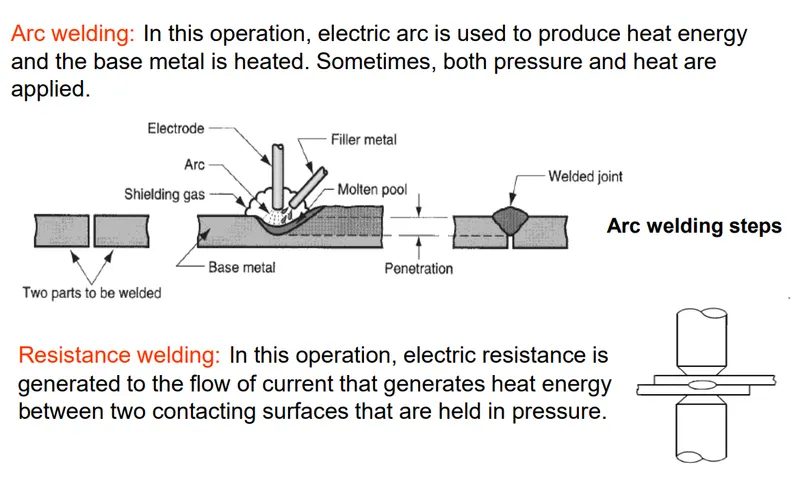
In fusion-welding processes, heat is applied to melt the base metals. In many fusion welding processes, a filler metal is added to the molten pool during welding to facilitate the
process and provide strength to the welded joint. When no filler metal is used, that fusion welding operation is referred to as an autogenous weld.
Types: Arc welding, Resistance welding, Oxyfuel gas welding,
electron beam welding, laser welding
Mechanical Joining:
- Riveting
- Caulking
- Bolting
- Shrink fitting
- Folding
Riveting
Riveting is the general term for joining with rivets/fasteners. You can find many types of riveting and we have described some of them below.
The principle of riveting is to join two or more plates mechanically by a joint. The joint is placed in a hole in the plates and forced mechanically to deform and thereby lock the plates.
Self-piercing riveting (SPR)
The principle is that it fastens together with two or more sheets of material mechanically with a self-piercing rivet. The rivet pierces the top sheet and the joining is achieved when the rivet pierces the bottom sheet partially, deforms the material into the die, and thereby forms a mechanical interlock. Often a layer of adhesive is used to keep the sheets in place while riveting.
caulking is a material used to seal joints or seams against leakage in various structures and piping.
Hemming and seaming are two similar metalworking processes in which a sheet metal edge is rolled over onto itself. Hemming is the process in which the edge is rolled flush to itself, while a seam joins the edges of two materials.
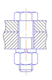
A bolted joint is one of the most common elements in construction and machine design. It consists of a male threaded fastener (e. g., a bolt) that captures and joins other parts, secured with a matching female screw thread. There are two main types of bolted joint designs: tension joints and shear joints.
3.
Resistance Welding:
Resistance welding is generally used to join two plain metal work pieces together. An electric current is delivered to the metal sheets (or any workpieces being joined) through weld electrodes which apply force to the sheets. This force is then converted to heat. The heat is generated so that it melts the metal at the point where they join – the point of ‘resistance’ between the faying surfaces. The electrode then extracts heat from the molten weld area which forms a weld nugget at the point where it solidifies. A force is applied before, during, and after a current is applied, which confines the contact area.
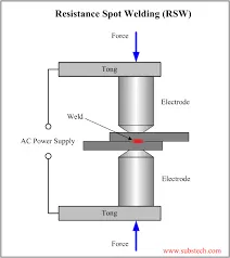
Types of Resistance Welding
There are many resistance welding processes with different uses, such as spot welding, seam welding, and butt welding. Each one has a different specific welding application that makes it optimal for a particular situation.
Resistance Spot Welding
Resistance spot welding has been used extensively in the automotive industry for the joining of steel and in the aerospace industry for airframe components made from aluminum alloys. It is one of the oldest and simplest forms of resistance welding, in which a weld nugget is produced by passing an electric current between the two metal components whilst they are held together between electrodes, typically made from copper-based alloys due to its superior conductive properties.
Resistance Seam Welding
Resistance seam welding is a variation of the standard spot welding form, however, instead of spot one nugget, a series of overlapping nuggets is produced. This is usually done by replacing the conventional spot welding electrodes with wheels, which turn as the parts are fed between them. The process thus produces a continuously welded seam rather than a single spot. Seam welding is often used in the production of thin sheet, leak-tight containers such as fuel tanks, and is generally unsuitable for welding aluminum.
Resistance Projection Welding
Resistance projection welding is a form of resistance welding where the electricity, force, and weld time are concentrated on raised ‘projections’ across the surface. Projection welding is generally used for welds using thicker materials than the thinner metal pieces that spot welding is usually required for, and often not metals. It is used primarily in the electrical, automotive, and construction industries.
Resistance Butt Welding
Resistance butt welding is a process in which the two components of a similar cross-section can be joined together in one operation that takes place simultaneously across the entirety of the affected object, rather than just in small spots. The welding application of butt welding is often in wires and rods with small diameter measurements, generally up to about 16mm diameter.
Flash Butt Welding
Flash butt welding is similar, but in this case, the energy transfer is primarily provided by the resistance heat arising from the parts themselves. This is a faster type of resistance welding where the welder joins the parts by applying some pressure, then by passing a heavy current through the joint which burns away surface irregularities. After the weld has generated enough heat, the parts are connected by applying heat and pressure simultaneously. This produces a forge butt weld with no melted metal remaining in the joint.
4. Fusion Welding:
Fusion welding is a process that uses heat to join or fuse two or more materials by heating them to a melting point. The process may or may not require the use of filler material. External application of pressure is not required for fusion welding processes, except for resistance welding, where substantial contact pressure is required during welding for sound joining.
Fusion Welding Processes
Fusion welding processes can be grouped according to the source of the heat, for example, electric arc, gas, electrical resistance, and high energy.
These processes include:
Arc Welding Processes - with the most common processes being:
Shielded Metal Arc Welding (SMAW), also known as manual metal arc welding (MMA or MMAW), flux shielded arc welding, or stick welding. Suitable for welding ferrous and non-ferrous materials in all positions.
Metal Inert Gas Welding (MIG) and Metal Active Gas welding (MAG), also known as Gas Metal Arc Welding (GMAW). MIG and MAG welding is the most common arc welding process, in which an electric arc forms between a consumable wire electrode and the workpiece leading them to melt and join. Both use a shielding gas to protect the weld from airborne contaminants, or oxidation in the case of MIG welding.
Tungsten Inert Gas Welding (TIG), also known as Gas Tungsten Arc Welding (GTAW). This arc process uses a non-consumable tungsten electrode to create the arc between the electrode and the base plate. Inert shielding gas is used to protect from oxidation or other atmospheric contamination. This process can be used autogenously on thin parts but will require the addition of a wire, rod, or consumable to be added for thicker parts.
Plasma Arc Welding (PAW). This process uses an electric arc created between an electrode and the torch nozzle. The electric arc ionizes the gas (usually argon) in the chamber creating what is called a 'plasma.' It is then forced through a fine bore copper nozzle that constricts the arc and directs it to the workpiece, allowing the plasma arc to be separated from the shielding gas (which is usually made from a mixture of argon and hydrogen).
Submerged Arc Welding (SAW). This frequently-used arc welding process uses a continuously fed consumable electrode and a blanket of fusible flux which becomes conductive when molten and provides a current path between the workpiece and the electrode. The flux also prevents spatter and sparks while suppressing ultraviolet radiation and fumes.
Flux Cored Arc Welding (FCAW). Developed as an alternative to SMAW, this process uses a continuously fed consumable electrode with a flux and a constant voltage or constant current power supply. Sometimes using a shielding gas this process can also just use the flux to protect the atmosphere.
5. 3-2-1 Principle:
3-2-1 Principle of Location
The 3-2-1 principle of location (six-point location principle) is used to constrain the movement of the workpiece along the three axes XX, YY, and ZZ. This is achieved by providing six locating points, 3 pins in the base plate, 2 pins in the vertical plane, and 1 pin in a plane that is perpendicular to the first two planes.
Degree of freedom controlled by the 3-2-1 location principle
Pins D and E are in a plane parallel to the plane containing the X and Z axes. It prevents the rotation of components about the Z-axis (6, 7 degrees of freedom) and the movement of the body along Y-axis towards one direction (8 degrees of freedom).
The last pin F is in a plane parallel to the plane containing the Y and Z axes. It restricts the movement component along X-axis in one direction.
Three remaining degrees of freedom 10, 11, and 12 are unrestricted. It facilitates the loading of the component in the fixture. These three degrees of freedom may restrict after loading components by using clamping devices.
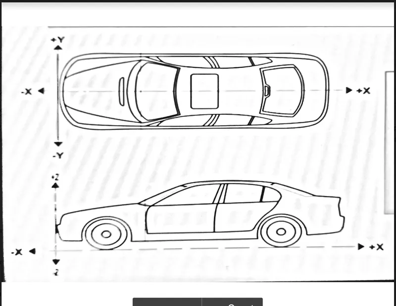
- It defines the exact position of each product in the vehicle from the fixed origin.
- It ensures flawless design for assembly
- while designing lines, all the designs are carried out relative to the bodyline.
- It assists in easy location of different parts in a vehicle.
- It aims in creating a standardized system.
- It assists in Quality Checks.