Week 2:- BiW Fixture Basics Challenge
1. What is the process of project execution activity?
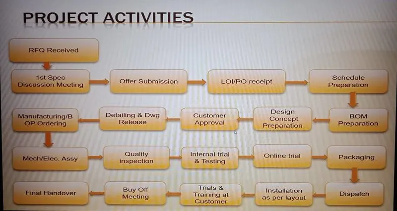
Project activities are those basically are being processed or being practiced in general project of BIW begins. Project activities are task from start to end of project. There are various step involved in project. Below fig. show flow chart of project activitieS.
RFQ:
Training at Customer In BIW fixture design project begins. It starts with basic requirement or RFQ that we receive from customer, RFQ means request for quotation where in customer give his requirement specification etc. in form of some document or data to study or to work on information include such as technical offer, commercial offer, timeline of project Based on that we have processing to execute project
1 specification discussion meeting & offer submission
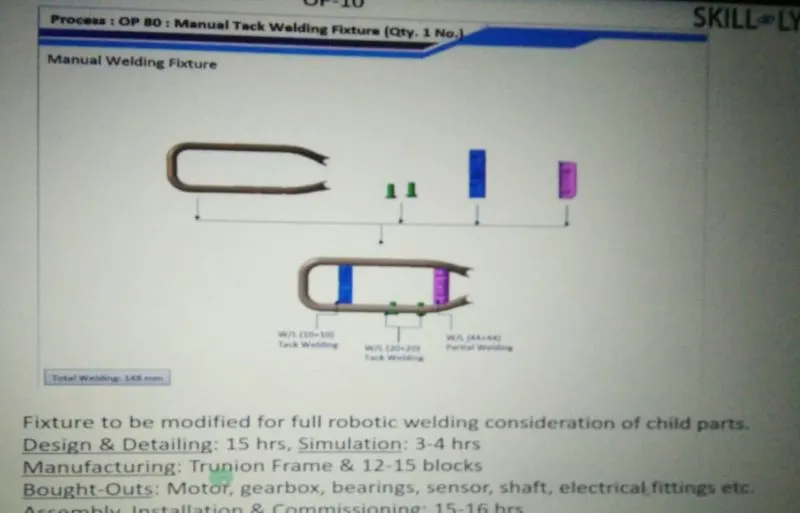
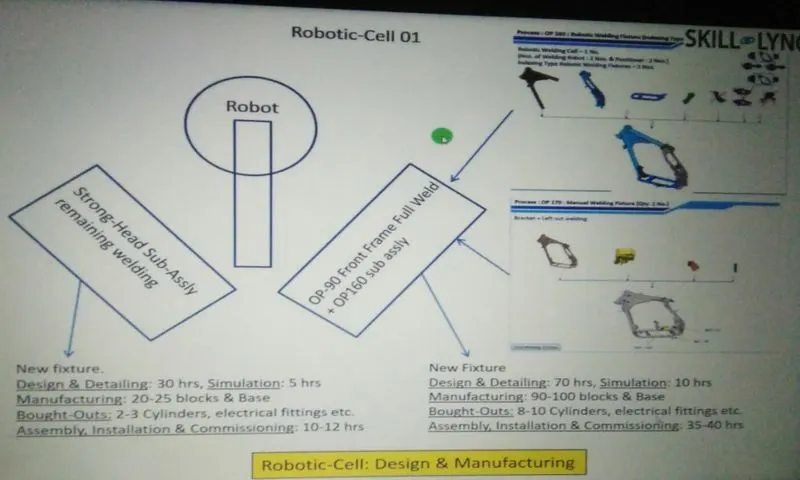
In this the documents related technical offer, commercial offer, project execution, timeline required to complete the project are prepared. The time required to 3D design, analysis of design, drawing & detailing, manufacturing assembly & commissioning etc. is considered. Then cost of all operation is considered By considering these kinds of things the offer is prepared & submitted to customer Below fig show document that how technical offer is made.
PO/LOI:
Once we submitted offer customer will study the offer at the same time he will get offer from different supplier & vendor. He compares these technical offers & based on cost whichever suit best for his requirement. Then he will release LOI or PO with its terms & conditions as stated earlier.
Schedule Preparation;in project each activity depends on previous activity. So if previous activity has not completed on time it will cause delay in next activity date is fixed so that it will move further. Each activity has assigned specific time i.e. when activity is starting & when it is ending? So we have some back plan so that final date comes to close final delivery date. There need to be proper scheduling to be done to complete project in time. "On time delivery" is one of the major requirements from customer side also customer wants commitment must be follow in respect of time.
BOM Preparation;
BOM preparation is listing down of part list which includes bought out parts, vendor parts, and consumable items with qty. of each item. Through BOM preparation material budget will be fixed. B/O parts include motor, gear box, cylinder, pneumatic & hydraulic valves etc. Also vendor parts include all machined, fabricated parts etc. whereas consumable includes like oil, grease, glue, loctite etc...
Design concept preparation Further step is to design a concept. A concept is based on all specification, received data from customer as 3D data of car panel, drawing, drawing std., design std., manufacturing std. After studying all data design concept is build
Customer approval;
As design concept ready then it is send to customer for its approval It is also known as design approval process (DAP) or customer approval process. In that customer will check that all his specification consider or not in specifications. Whether it is as per technical offer submitted then only he approves prepared concept. Some points will be raised by customer. These changes are updated to design team by project team Design team again work on it some modification or changes are necessary to improve design like clamping need to be improved or this mechanism will work fine, sensor should be of this make. These changes are again updated to customer. Once he gave final approval we will move further for detailing & dwg, release
Detailing & Dwg, release:
in detailing all assemblies broken down into its child parts. Parts of assembly are segregated into std. as well as manufactured. For std. parts own data sheet or specification sheet prepared to purchase it from catalogue, eg. motor power, motor current rating, torque produced, shaft rpm which suit for our application. For vendor parts all detail should be provided on dwg. Like all dimension of part with tolerance, surface finish, surface treatment, hardness, welding note all should be mention on dwg. These dwgs are checked & released for manufacturing.
Manufacturing & B/O ordering:
Manufacturing department will receive all dwg to start manufacturing of items like mylar, blade, riser, base frame. Also purchase team will place order for B/O parts like motor, gearbox, cylinder & valves. As material get ready, QC team should inspect all part received is as per specification or not otherwise it will create issue later which will waste our time
Mechanical & electrical assembly:
After qc check, parts are available for assembly. A station is integration of all mechanical as well as electrical assembly. Assembly team will do all assembly as per dwg. All station are build as per layout Then again qe team should be involved for checking assembly as per final dwg, all coordinate dimension should be ok as per design data. Internal trial & testing: After approval of qe team, Internal trials & testing started. The first stop involves putting assembly in fixture manually to check that it being fox properly, locating pin match with hole, clamping is ok. loading & unloading of part is easy. Also operating height is also checked it is ergonomically correct. Then start taking trials on fixture for welding feasibility, gun approachability in fixture.
Then go for online trial Online training:
After successful of trial next step is online training. In online training has two mode manual & automated in online trial systern is run through control panel All sensor actuator, motor current & temperature, noise, all alarm also safety should be tested All process must be executed as por sequence also cycle time mout. In online training system run for certain cycle & actual production taken to ensure system rut successfully
Packaging:
After trial get successful, customer give approval to dispatch system. To dispatch whe system needs to disassemble station wise & pack properly. Delicate material should be packed properly otherwise there is chance of damage aesthetically or functionally during transportation. During packaging labeling, special handling instruction should be pasted on particular parts to convey message of taking care during handling & transportation.
Dispatch:
All material transported at customer site through trucks, container, and ships or by air. Installations: All system is assembled & installed at customer end as per layout approved initially imm DAP. All station, robots, conveyor mounted as per distance specified in layout. Robot arm should be reachable to station, pick & drop point. It shouldn't foul with other equipment. Also some adjustment should be provided for leveling purpose at robot conveyor base, station base frame like leveling stud to align with other equipment. Layout is always specified at the time of initial design stage & it has to be approved by customer.
Trial & training at customer end:
Once installation is done trial start at customer end. So there will be production trial, online trial. Production trial is necessary because at the time of designing fixture, it also committed no, of unit that will be manufactured from that fixture also whether it is meeting quality, bench mark or not. Also in technical offer it is committed that there will be 100 units per 8hrs shift will manufactured from that fixture with weld quality. So during production trial fixture capability will be ensured. Once this goal is achieved then there will be training to operator, staff member engineers to let them to understand how process is working?
Buy off meeting:
Once training is completed there is buy off meeting between customer & project team with discussion on if there other things need to be incorporated, anything missing that described in LO/PO of offer submission. Then customer will raise paint or sometimes customer wants modification that will lead to extra quotation extra costing according work is done as por buy af mooting.
FINAL HANDOVER;
The final handover is the very last stage of any home build or big renovation project. It’s the point at which: The builder will normally contact you a week before the handover date to arrange access for a pre-handover inspection (also known as a ‘final inspection’).
2.What are the types of joining processes?
- The material being joined - similar or dissimilar, aluminum, iron, copper, etc.
- Type of assembly- Temporary or permanent.
- Economy.
- Service condition - load, temperature, etc.
Difference Between Soldering And Brazing
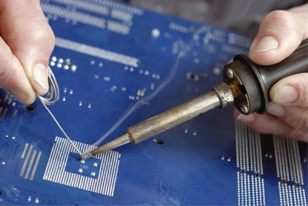
Solder and brazing are similar, in both cases a filler material having the melting point much lower than parent material added into the gap between work-pieces by capillary action. The characteristics of this metal joining method may vary in some special application.
|
Soldering |
Brazing |
|
The solder joints are the weakest joints. They are not intended load. |
This can be used to carry the burden to some extent. Properly made brazing may be stronger than the metal to be joined, but they are not as strong as welded joints. |
|
Soldering is done by heating filler metal up to 450 degrees Celsius (840 °F). |
Brazing joins materials by heating the filler metal with the melting point above 450 degrees Celsius, but below the melting point of the base metal. |
|
An alloy of lead and tin known as solder used as filler material. |
Alloys of copper with zinc, silver and aluminium are the common brazing filler material. |
|
Close / fine contact between the base material not necessary |
Fine contact of the base metal is necessary; they should not have an interfering layer between them. |
|
It has the least impact on the base material. |
In the brazing of the greatest strength is achieved through some chemical reaction between solder alloy and metal on each side. |
|
Solders are more vulnerable to oxidation since they are made of the alloy of tin and lead. (In special cases zinc-aluminium alloys used as filler to avoid this problem) |
Susceptible to oxidation but not much as in soldering. |
|
The commonly used fluxes for soldering are zinc chloride and HCl. |
Fluxes are fluorides, chlorides, Borax and boric acid. |
|
Lower cost, inexpensive filler material, low temperature virtually no cleaning required after soldering. |
Costlier than soldering. |
|
It is particularly useful when the heat can damage or deform the materials. Commonly electrical components are soldered to prevent heat damage. |
Brazing used for joining dissimilar metal, fastening of pipe fittings and leak proof joints. |
SOLDERING;
BRAZING;
- Arc welding
- Resistance welding
- Gas welding
- Forge welding
- Other welding processes
- Brazing, soldering and braze welding
Each process is identified within the group by a numerical index or reference number. For example, the MIG welding process has a reference number of 131 which is derived as follows:
- 1 - Arc welding
- 3 - Gas-shielded metal arc welding
- 1 - Metal arc inert gas welding
The main arc welding process reference numbers are:
- 111 manual metal arc welding;
- 114 self-shielded tubular-cored arc welding;
- 121 submerged arc welding with one wire electrode;
- 125 submerged arc welding with tubular cored electrode;
- 131 metal inert gas welding (MIG welding);
- 135 metal active gas welding (MAG welding);
- 136 tubular cored metal arc welding with active gas shield;
- 141 tungsten inert gas arc welding (TIG welding);
- 15 plasma arc welding;
The reference numbers are used as a convenient way of identifying the welding process in documentation such as welding procedures (BS EN ISO 15614 series) and welder qualification (BS EN 287 and BS EN 9606 series) records.
Process options
Factors which must be taken into account when choosing a suitable welding or joining process are:
- material type
- product form: plate or tubular
- quality and strength requirements
- degree of mechanisation
- capital cost
Although consideration of these factors will identify the most suitable welding process, the choice within a company may be restricted by the cost of implementing a new process, availability of plant or current workforce skill. Welding and joining processes available to the welding engineer can be separated into the following generic types:
- Fusion
- arc
- gas
- power beam
- resistance
- Thermomechanical
- friction
- flash
- explosive
- Mechanical
- fasteners
- Solid state
- adhesive
- soldering
- brazing
The suitability of the processes for welding and joining materials, joint types and components are shown in Table 1.
Table 1. Suitability of the processes for welding and joining materials, joint types and components
| Process | Index no. | Steel | Stainless | Al | Butt joint | Lap joint | Plate | Tube | Portability | Manual | Mechanised Automated |
Site |
|---|---|---|---|---|---|---|---|---|---|---|---|---|
| Arc | 1 | Yes | Yes | Yes | Yes | Yes | Yes | Yes | Yes | Yes | Yes | Yes |
| Gas | 3 | Yes | Possible | Possible | Yes | Yes | Yes | Yes | Yes | Yes | No | Yes |
| Laser | 52 | Yes | Yes | Possible | Yes | Yes | Yes | Yes | No | No | Yes | No |
| Resistance | 2 | Yes | Yes | Yes | Possible | Yes | Yes | Possible | Possible | Yes | Yes | No |
| Friction | 42 | Yes | Yes | Yes | Yes | No | Yes | No | No | No | Yes | No |
| Brazing | 9 | Yes | Yes | Yes | No | Yes | Yes | Possible | Yes | Yes | Possible | Yes |
| Fasteners | none | Yes | Yes | Yes | No | Yes | Yes | No | Possible | Yes | Yes | Yes |
| Adhesives | none | Yes | Yes | Yes | No | Yes | Yes | Yes | Yes | Yes | Possible | Yes |
In selecting a suitable process, consideration must also be given to the type of application, for example, the portability of equipment, whether it can be used on site, whether it is manual or mechanised, and the overall cost of the welding plant.
Fusion welding processes
When welding using a fusion process, the edges of a component are melted together to form weld metal.
Table 2. Heat source, mode of shielding, thickness range and metal deposition rates for various fusion processes
| Process | Heat source | Shield | Parent metal thickness mm |
Deposition rate kg/hr |
|---|---|---|---|---|
| Arc | ||||
| MMA | Arc | Gas/flux | 1-100 | 1-4 |
| MIG | Arc | Gas | 0.5-100 | 1-8 |
| TIG | Arc | Gas | 0.1-100 | 1-4 |
| SAW | Arc | Flux | 5-250 | 5-20 |
| ES/EG | Resistance/arc | Flux/gas | 5-250 | 5-20 |
| Stud | Arc | - | 4-20 | - |
| Gas | ||||
| Oxyfuel | Flame | Gas | 0.6-10 | 1-2 |
| Power beam | ||||
| Laser | Radiation | Gas | 0.2-25 | - |
| EB | Electrons | Vacuum | 0.2-250 | - |
| Resistance | ||||
| Spot/Seam | Resistance | - | 0.2-10 | - |
| Thermit | ||||
| Thermit | Chemical | Gas | 10-100 | - |
Table 2 shows heat source, mode of shielding, thickness range and metal deposition rates for a range of fusion processes. Although fusion welding is one of the simplest joining techniques, problems likely to occur include porosity in the weld metal, and cracking in either the weld or heat affected zone (HAZ). Porosity is avoided by ensuring adequate shielding of the weld pool and, for materials such as aluminium, the addition of filler wire.
Consideration of the joint design and the chemistry of the weld metal will prevent weld metal cracking. HAZ cracking which might be caused by hydrogen, is avoided by using low hydrogen consumables and controlling the heat input and the rate of cooling of the parent metal.
3.What is Resistance Welding & its application in the automotive sector?
What is Resistance Welding?
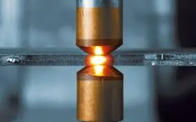
Resistance welding can be defined as; it is a liquid state welding method where the metal-to-metal joint can be formed within a liquid state otherwise molten state. This is a thermoelectric method where heat can be generated at the It is a thermo-electric process in which heat is generated at the edge planes of welding plates because of electric resistance and a weld joint can be created by applying low-pressure to these plates. This type of welding uses electric resistance to generate heat. This process is very efficient with pollution free but the applications are limited because of the features like equipment cost is high, and material thickness is limited.
Resistance Welding Working Principle
The working principle of resistance welding is the generation of heat because of electric resistance. The resistance welding such as seam, spot, protection works on the same principle. Whenever the current flows through electric resistance, then heat will be generated. The same working principle can be used within the electric coil. The generated heat will depend on material’s resistance, applied current, conditions of a surface, applied the current time period
This heat generation takes place because of the energy conversion from electric to thermal. The resistance welding formula for heat generation is
Where
- ‘H’ is a generated Heat, and the unit of heat is a joule
- ‘I’ is an electric current, and the unit of this is ampere
- ‘R’ is an electric resistance, and the unit of this is Ohm
- ‘T’ is the time of current flow, and the unit of this is second
The generated heat can be used to soften the edge metal to shape a tough weld joint with fusion. This method generates weld with no application of any flux, filler material, and shielding gases.
Resistance welding, sometimes called electric resistance welding (ERW),is a process by which metals can be joined together by applying pressure and conducting a strong electric current through the metal combination to heat up the welding joint and melt the metals, forging them together.
It has various forms and applications, and no other materials are needed, which makes it a highly cost effective process
How Does Resistance Welding Work?
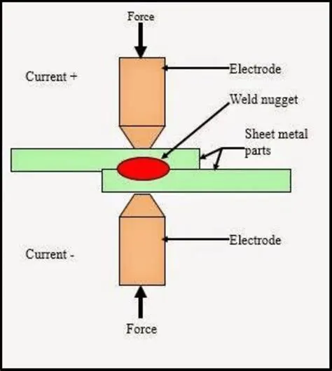
Resistance welding is generally used to join two plain metal work pieces together. An electric current is delivered to the metal sheets (or any work pieces being joined) through weld electrodes which apply force to the sheets. This force is then converted to heat. The heat is generated so that it melts the metal at the point where they join – the point of ‘resistance’ between the faying surfaces. The electrode then extracts heat from the molten weld area which forms a weld nugget at the point where it solidifies. A force is applied before, during and after a current is applied, which confines the contact area.
Types of Resistance Welding
There are many resistance welding processes with different uses, such as spot welding, seam welding, and butt welding. Each one has a different specific welding application that makes it optimal for a particular situation.
1. RESISTANCE SPOT WELDING
Resistance spot welding has been used extensively in the automotive industry for the joining of steel and in the aerospace industry for airframe components made from aluminium alloys. It is one of the oldest and simplest forms of resistance welding, in which a weld nugget is produced by passing an electric current between the two metal components whilst they are held together between electrodes, typically made from copper-based alloys due to its superior conductive properties.
2. Resistance Seam Welding
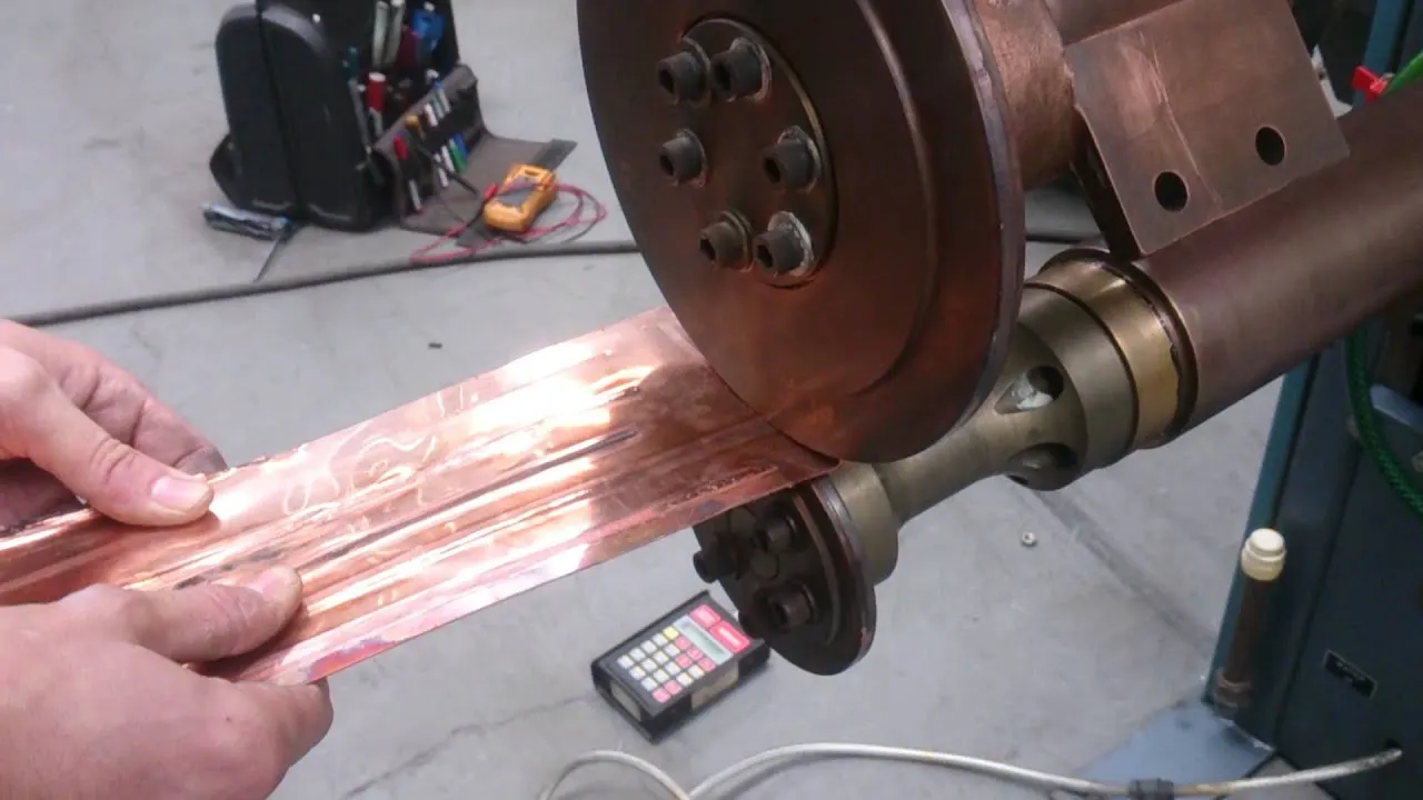
Resistance seam welding is a variation of the standard spot welding form, however instead of spot one nugget, a series of overlapping nuggets is produced. This is usually done by replacing the conventional spot welding electrodes with wheels, which turn as the parts are fed between them. The process thus produces a continuous welded seam rather than a single spot. Seam welding is often used in the production of thin sheet, leak-tight containers such as fuel tanks, and is generally unsuitable for welding aluminium.
3. Resistance Projection Welding
Resistance projection welding is a form of resistance welding where the electricity, force, and weld time are concentrated on raised ‘projections’ across the surface. Projection welding is generally used for welds using thicker materials than the thinner metal pieces that spot welding is usually required for, and often not metals. It is used primarily in the electrical, automotive and construction industries.
4. Resistance Butt Welding
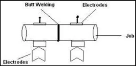
Resistance butt welding is a process in which the two components of similar cross section can be joined together in one operation that takes place simultaneously across the entirety of the affected object, rather than just in small spots. The welding application of butt welding is often in wires and rods with small diameter measurements, generally up to about 16mm diameter.
l FLASH Butt Welding
Flash butt welding is similar, but in this case the energy transfer is primarily provided by the resistance heat arising from the parts themselves. This is a faster type of resistance welding where the welder joins the parts by applying some pressure, then by passing a heavy current through the joint which burns away surface irregularities. After the weld has generated enough heat, the parts are connected by applying heat and pressure simultaneously. This produces a forge butt weld with no melted metal remaining in the joint.
Application:
- Resistance welding is widely used in automotive industries.
- Projection welding is widely used in production of nut and bolt.
- Seam welding is used to produce leak prove joint required in small tanks, boilers etc.
- Flash welding is used to welding pipes and tubes.
Advantages
- Similar and dissimilar metals are capable of being welded
- Highly automated
- Efficient with high production rate and high welding rate
- Cost-effective
- Environment-friendly, produces little waste or pollution
- No need for filler metal or extraneous materials such as rods, fluxes, inert gasses, oxygen, or acetylene are required
Disadvantages
- Complex and often high-cost machinery – a resistance welding machine generally requires a high level of technically trained personnel to use
- The thickness of the work piece is often limited
- It is less efficient for high conductive materials
- High electric power required
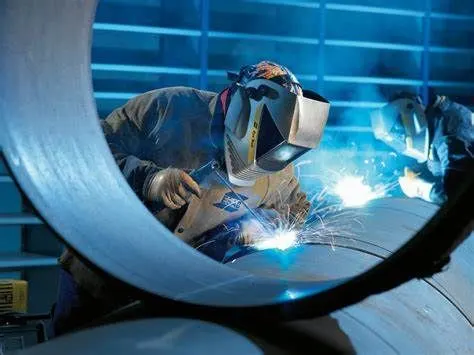
Have you come across the term fusion welding and wondered what it means? Like any other welding process, fusion welding is used to join two or more objects using heat. However, this welding process is unique since you can either use filler materials or not, and it does not require the application of external pressure. Assuming the two materials to be welded are made of similar materials, heat from the welding rig melts their surfaces, allowing the objects to fuse.
How Fusion Welding Works
From the definition, fusion welding joins edges of different materials by heating them to a melting point. Sometimes, a filler material is necessary if there are gaps in the joint you are making. The materials will undergo many phase transitions because the heating process creates a heat-affected zone (HAZ) on the material(s).
Fusion welding takes place when the molten base materials join with molten fillers. The heat that melts the materials can be applied to the joining zone or developed externally at the intended weld point. For instance, you can pass current via an electrical contact resistance between the edges of the materials you are welding together to develop the heat you need.
The Difference between Fusion Welding and Non-Fusion Welding
Whereas fusion welding must include heat to the melting point, non-fusion welding can occur under low heat intensity since it does not involve the melting of the parent materials. Additionally, no filler materials are needed in non-fusion welding. Examples of non-fusion welding include soldering, brazing, and pressure welding.
What are the Basic Types of Fusion Welds
Understanding different types of fusion welding processes are critical when discussing fusion welding. Based on the heat source, fusion welding processes can be categorized as follows:
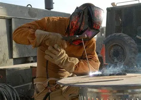
Arc welding is among the preferable ways of a fusion welding process. True to the hype, arc welding connects two parts (or more) using an electric arc. The reason is that electric arcs generate heat levels that reach up to 6,000 degrees Fahrenheit, making them ideal for fusing hard metals and materials. Additionally, arc welding is also suitable for offshore applications where you can perform underwater fusion welding. Commonly, arc welding processes include:
- Shielded Metal Arc Welding (SMAW): Commonly used for welding non-ferrous and ferrous materials in nearly all positions.
- Metal Gas Arc Welding: An electric arc is forming between the material and consumable wire electrode, allowing them to melt and fuse. Shielding gas is used to avoid airborne contaminants and oxidation for MIG welding.
- Tungsten Inert Gas Welding: Non-consumable tungsten is used in creating an arc between the basal plate and electrode. To avoid oxidation and atmospheric contaminations, an inert shielding gas is used.
- Plasma Arc Welding (PAW): In this arc, an electric arc is formed between the torch nozzle and electrode. The argon gas (plasma), usually in the chamber, is ionized by the electric arc.
- Submerged Arc Welding (SAW): It uses a continuously fed consumable electrode together with a flux. The flux prevents spatter and sparks and becomes conductive in a molten state, hence providing the current electrode and material path.
- Flux Cored Arc Welding (FCAW): The process is also continuously fed consumable electrodes with flux; hence it serves as an alternative to SMAW.
2. Laser Beam Welding (LBW)
As the name suggests, this is a fusion welding process that uses a focused laser beam as its energy heat source. The high heat levels have precision rates useful for joining metals and polymers. It is a fast and automated process that uses light to generate heat.
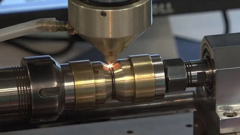
You can perform an LBW in the air instead of a vacuum, unlike the electron beam fusion welding processes.
3. High-Energy Welding Processes
It is a fusion welding process that produces heat through light radiation. To fuse the different materials, you blast the radiation light to the materials’ surface, making them become hot and start to melt. The workpiece will later merge as they gradually cool down.
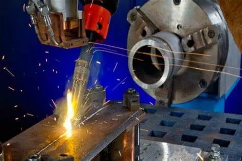
These are typical examples of high-energy fusion welding processes.
4. Electronic Beam Welding (EBW)
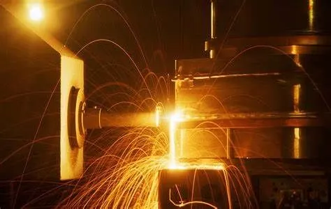
The electronic beam welding process involves high-velocity electrons to join workpieces together. The electrons produce intense heat that enters the materials changing their solid-state to molten. EBW welds are deep and thin and can only be achieved under specific atmospheric conditions.
5. Friction Welding
When applying the friction welding technique, the different materials are joined together using mechanical friction. There are various ways to perform mechanical friction on aluminum, steel, and sometimes wood materials.
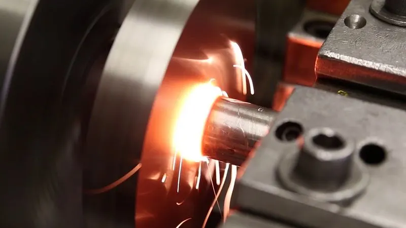
The process of mechanical friction is arduous. However, the heat you generate will soften both materials, creating a bond after mixing and cooling afterward.
There are various ways to perform friction welding, which determines the kind of joints you will have. These processes include:
. Friction stir welding
- Rotary friction welding
- Friction stir spot welding
- Linear friction welding
When applying friction welding, there is no need for shielding gas, flux, or filler metals. The process is ideal for applications that are considered lightweight and for non-weldable materials like some forms of aluminum alloys.
3-2-1 Principle of Location
The 3-2-1 principle of location (six point location principle) is used to constrain the movement of workpiece along the three axes XX, YY, and ZZ. This is achieved by providing six locating points, 3 pins in base plate, 2 pins in vertical plane and 1 pin in a plane which is perpendicular to first two planes.Degree of freedom controlled by 3-2-1 location principle
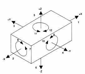
In this method, 9 degrees of freedom is controlled.
Pins A, B, C on the base plane ( a plane parallel to the plane which contains X and Y axis) restrict the rotation of component about X axis and Y axis. It also limit the downward movement of component along z axis. Ie. 1,2,3,4 and 5 degrees of freedom is restricted.
Pins D, E is in plane parallel to the plane containing X and Z axes. It prevents the rotation of component about Z axis (6, 7 degree of freedom) and the movement of the body in along Y axis towards one direction (8 degree of freedom).
- Basic Rules For Location
- Choosing Locating Surfaces
The last pin F is in a plane parallel to plane contains Y and Z axes. It restricts the movement component along X axis in one direction.
Three remaining degree of freedom 10, 11, 12 is unrestricted. It facilitates the loading of the component in the fixture. This three degree of freedom may restrict after loading of component by using clamping devices.