Week 2:- BiW Fixture Basics Challenge
JOINING PROCESSES IN CAR BODY CONSTRUCTIONS:
Joining and forming are two common types of manufacturing processes. Manufacturing companies often rely on one or both types of processes to convert raw materials into finished products. While joining and forming have a similar goal, however, they aren’t the same. There are stark differences between joining and forming manufacturing processes, which you can learn more about in the following post.
What Are Joining Processes?
Joining processes are characterized by their ability to fuse or “join” two or more components for the purpose of creating a different object, such as a ready-to-sell consumer product. Most materials can be joined — and there are typically multiple ways to join them. Two-by-fours, for instance, can be nailed or bolted together, whereas sheet metal can be welded or soldered together.
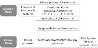
Sheet metal joining process selector
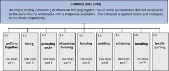
All joining processes involve joining two or more components, and most joining processes require the use of a separate tool or tools. With the help of a tool, such as a nailgun, the components are joined.
MANUFACTURING PROCESS| METAL JOINING PROCESS| WORKING OF METAL JOINING PROCESS -
JOINING PROCESSES
Common types of joining processes used in the manufacturing industry include the following:
- Welding
- Brazing
- Soldering
- Bonding
- Nailing
- Screwing
- Bolting
- Riveting
- Clinching
- Stapling
- Press fitting
What Are Forming Processes
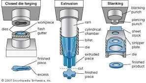
Forming processes, on the other hand, involve the physical manipulation of an object. With forming, an object is physically deformed to achieve a different size and/or shape. When an object is exposed to physical stress, such as heat or pressure, it typically deforms. Depending on the type of material from which the object is made, it may expand when exposed to heat or pressure. Forming process follow this same principle by using heat and/or pressure to deform an object.
Common types of forming processes used in the manufacturing industry include the following:
- Tube bending
- Forging
- Cold rolling
- Hot rolling
- Extrusion
- Pressing
- Bending
- Shearing
- Stamping
- Coining
- Ironing
The primary difference between joining and forming processes is that joining processes involve fusing multiple components together, whereas forming processes involve deforming a single object. It’s also worth noting that forming processes tend to create less waste than joining processes. Joining processes often create chips or swarf. In comparison, little or no chips or swarf is created with forming processes.
Mechanical joining processes
In car body constructions, mechanical joining procedures are used to join components of differing materials. This applies to many connections with (and between) steel, aluminum, and fiber composites. Simufact supports simulation of these processes, including self-piercing riveting (SPR), blind riveting, flow-hole screwing and clinching.
Joints have a significant impact on stiffness, energy absorption potential (crash-suitability), and the dimensional accuracy of car body panels. In mechanical and thermal joining, the importance of adhesive bonding (hybrid joining) is on the rise.
The adhesive not only serves as a sealant and for corrosion protection, but it also creates a bond joint between thin components. Simufact offers functions to consider adhesives in the joining process.
Self-piercing riveting
Self-piercing riveting involves the joining of sheet metal combinations by piercing a rivet through a component’s parts. The components interlock as the sheet on the punch side is deformed into the sheet on the die side, via a self-piercing rivet, producing a positive joint. The process requires access to the joining area from both sides.
Blind riveting
Blind riveting only requires you to have access to the joint from one side; however, the two components that are to be joined must be pre-punched. The blind rivet is spread apart on the blind side with a mandrel. This, in combination with the shape of the blind rivet’s head, creates a positive joint.
Flow-hole screwing
This process is a self-piercing, self-tapping, screw joint which only requires access from one-side.
Clinching
Clinching (also known as pressure joining, press joining, and TOX-Clinching [TOX® PRESSOTECHNIK]) is a proven clinching method in which metal sheets are permanently joined without the use of any additional materials. This method is well-suited for joining metal sheets of differing thicknesses, as well as dissimilar materials with varying strengths.
Thermal joining processes
Thermal joining is still the most commonly used joining technique for similar metal-to-metal connections in car bodies, chassis, drivetrains, and exhaust systems. Welding and brazing techniques have a wide range of possible applications, which are usually achievable with low costs, high process robustness, and high joint strength.
Simufact supports you in the optimization of, among others, the following processes:
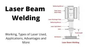
Laser beam welding
The procedure of laser beam welding involves a focused laser beam, serving as an energy source, directed towards a component via mirrors. At the point of contact, the laser melts the materials to form a bond. The advantages of laser welding are the high process speed, flexibility, and fine seams – which usually do not have to be reworked. Furthermore, laser welding opens up new possibilities within construction as it can be used for applications which are not easily accessible.
Read a detailed description of the application module.
Resistance spot welding
Resistance spot welding is the most frequently used process for the joining of steel alloys. It requires you to have access from both sides and is well-suited for components exposed to view.
See further details in the description of the application
Laser brazing
Laser brazing is a procedure for the firm bonding of materials. A liquid phase is produced by melting or diffusing a solder, which has a lower melting point than the components being joined. Laser brazing only requires access from one side and is also well-suited for components exposed to view.
SUSTAINABLE SUPPORT OF YOUR PRODUCT DEVELOPMENT PROCESS
Challenges of joining-process design
Joined assemblies and finished vehicles face different challenges.
Rely on Simufact solutions to sustainably improve your product development process. Simufact solutions help you in meeting the challenges of process design:
- Feasibility and durability of a joint
- Process stability
- Dimensional accuracy of the assembly
- Improved joint properties (strength, stiffness, fatigue resistance)
Feasibility and durability of a joint
There are a wide range of failures that fall under the category of feasibility: rivet penetration, resistance spot welding burns, or brazing gap formation. Furthermore, unfavorable process parameter can generate hidden failures.
Example: KS2 tests for determining the resilience of joints against diverse kinds of stresses.
-
Simulating the joint failure of a self-piercing rivet -
Simulating a failure during resistance spot welding (semi-symmetrical 3D model)
Process reliability
In large-scale vehicle production, undesired process fluctuations frequently occur.
In a worst case scenario, this will lead to the components requiring rework or being rejected during a quality audit. However, in the best case scenario, these fluctuations will already have been considered during the virtual process design.
When designing self-piercing riveting processes, the material thickness combinations of the components can be factored in, resulting in high process reliability and minimal tool exchange.
Simufact has developed a special solution to test and validate the variations within joining processes: The Joining Optimizer.
Joining Optimizer
The Joining Optimizer is a new add-on tool available for Simufact Forming – serving as an efficient solution in car body manufacturing. It shortens development times by automatic validation of self-piercing riveting and clinching processes.
The user can virtually test a wide range of material thickness combinations with various rivet models and tool combinations. This evaluation delivers a ranking list of technically feasible die-rivet combinations for a single material-thickness combination. An easy-to-understand traffic light indicator based on undercut, minimum bottom sheet thickness, max. punch force, final rivet head position, etc. visualizes the feasibility. All evaluations are stored in a database for knowledge management, reducing the efforts for re-evaluation of similar material-thickness combinations.
In a second, subsequent step, the Joining Optimizer Assembly helps optimizing the number of needed die-rivet combinations (best possible compromise) for a given set of material thickness combinations of an assembly – aiming at highest efficiency in serial production by minimizing the number of die and rivet changes.
Simufact has developed the Joining Optimizer in cooperation with Audi, which is employing this solution in their productive environment.
Dimensional accuracy and functionality of an assembly
Thermal joining processes have the disadvantage of induced residual stresses which can distort the dimensional accuracy of an assembly. Furthermore, phase transformations can result in localized microstructure distortions leading to qualitative or functional failures. Simulation helps you to find these weaknesses early on and supports the identification of appropriate countermeasures.
-
Component distortion in an inner door assembly (source: Audi) -
Component distortion caused by five spot welds
Improved product properties and durability tests
Taking the forming “history” of components into account is essential for the simulation of joining in order to increase the accuracy of crash and endurance tests. This helps to optimize the design of crash structures.
BENEFITS FROM USING SIMUFACT SIMULATION SOLUTIONS
Use of Simufact – your benefits
Our practically tested software products make it possible for you to virtually evaluate the majority of joining processes and to optimize them via controllable process parameters.
By using Simufact simulation solutions, the high number of physical tests can be reduced to a minimum. Virtual process testing helps you to avoid unforeseen effects and cost-intensive changes to the equipment. Using Simufact makes the development process more transparent allowing you to reach the desired quality and output quantity on time.
Simufact can be used in both the development of technology and production planning. We even support the most experienced users with a customized menu navigation.
Advantages overview
- Fewer real-life tests = lower testing costs
- Transparency in your development process
- Can be used in technology development and production planning
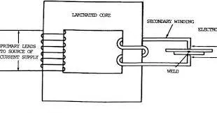
Resistance welding involves passing an electric current through the components being joined to heat the interface enough to cause melting of the materials at the interface. No filler material is used. A clamping force, which is applied during the heating process, holds the components in place until the joint has solidified. Resistance welding processes are used to join metals and include spot welding, seam welding, flash welding, and projection welding. A diagram of the spot welding process setup is shown in Figure 5.20. An example of a spot-welded joint is shown in Figure 5.21, which shows a cross section of a spot weld between two pieces of 2024 aluminum sheet.
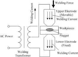
Figure 5.20. Diagram of the spot welding process setup.
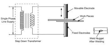
Figure 5.21. Cross section of spot welded 2024 aluminum sheet.
Resistance Welding
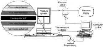
Resistance welding is an open-air fusion bonding technique that employs an embedded heating element at the interface to heat, via Joule heating, the interface between adherends as shown in Figure 4. It is important for the heating element to be compatible with the composites as it remains imbedded at the interface. Therefore, a single graphite prepreg ply can be used as the resistive element. Resistance welding is a very rapid process, with heating rates that can reach over 600°C (Tackitt et al., 1993). A consolidation force is applied throughout the process to develop mechanical, or intimate, contact between the welding surfaces and to collapse porosity at the interface. Eveno and Gillespie (1989) studied this process extensively under displacement control and identified the critical control parameters and proposed the following six distinct stages of bonding: (i) initial compaction, (ii) thermal expansion, (iii) melt flow during heating, (iv) melt flow during cooling, (v) solidification, and (vi) contraction. Houghton (1984) found that the bond strength could be improved by sandwiching the prepreg between two layers of thermoplastic films. The films provide for an easily deformable layer and some thermal insulation such that intimate contact is rapidly achieved at the interface. McKnight et al. (1992a) characterized experimentally the electrical efficiency and evaluated several end connection techniques for ease of use. Holmes et al. (1993) developed a power selection methodology to select the optimum power level and heating element sizes with consideration of power supply limitations and thermal uniformity. They found that substantial loads and power were required for resistance welding large areas. Consequently, an automated sequential resistance welding process has been developed to increase thermal uniformity by subdividing the bond into segments that can be individually controlled (Lambing et al., 1993).
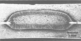
Fig. 4. Schematic of an automated resistance welder.
Health, Safety and Environmental Issues
8.04.1.2.1 Resistance Welding
Resistance welding is a group of welding processes in which coalescence is produced by the heat obtained from resistance of the work to the flow of electric current in a circuit and by the application of pressure (4). Examples of resistance welding include spot welding, induction welding, and flash welding. The most common type is spot welding. Resistance spot welding is a process that produces coalescence of metals at surfaces which are made to fit closely together for the purposes of making a joint. In a structure, a resistance spot weld has mechanical characteristics much like those of a rivet, although its soundness and strength are oftentimes many folds greater. Resistance spot welding processes are very effective for fabricating sheet metal articles where high rates of production are necessary. For this reason, spot welding has been particularly valuable in the automotive, aircraft, and appliance industries where high speed, repetitive welds are needed and relatively thin section sizes are welded.
Welding , Hardfacing , Cladding and Cutting of metals: Resistance Welding Process
materials processing | Definition, Examples, Types, & Facts | Britannica
Line Pipes
ERW pipes: LFW versus HFW pipes
ERW has, for many years, been used for making longitudinal seam welds in steel line pipe, principally for the use in low-grade pipeline applications. The advent of high-frequency induction techniques has led to significant improvements in weld quality, which in combination with greater control of the raw material chemical composition, and has led to the production of high-quality line pipe that is suitable for more stringent applications in oil and gas pipelines.
Although this product form has been used for many years in sour service environments and in North Sea for sweet service applications, there is some resistance to the use of ERW line pipe, particularly in stringent service applications. This lack of confidence generally is based on historical problems related to the reliability of electric resistance welds, the pressure reversals and preferential weld line corrosion, susceptibility to stress corrosion cracking.
The quality that can be achieved with modern HFW line pipe has improved dramatically with improvements in strip quality and greater understanding of the welding process and nondestructive testing technology. It offers closer dimensional control, which is of great value in pipe laying, and potentially significant cost savings over seamless pipe for similar applications.
The advantage of HFW over LFW process is that the HFW has a very narrow heat-affected zone (HAZ); thus the current flow and the heat are limited to a very small area. In this process two proximity conductors under a magnetic core are placed opposite to each other on the edges of the pipes to be welded. This proximity causes the edges to get heated. As it is heated a force is applied to bring the two faces together and a weld is made. Heating similar area with conventional ERW (EW in API 5L) will require significantly higher current and would result in a wider HAZ (Figure 3.2.1).
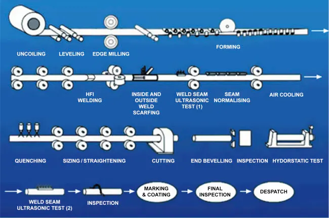
Figure 3.2.1. Typical HFW (induction) production flow line.
Resistance welding processes
9.1 Introduction
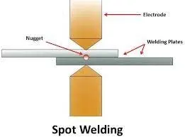
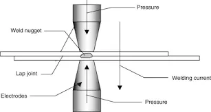
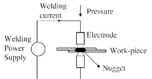
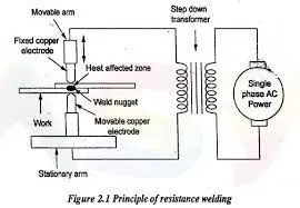
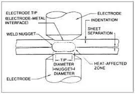
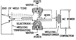
Resistance welding is a fusion welding process that requires the application of both heat and pressure to achieve a sound joint. The simplest form of the process is spot welding where the pressure is provided by clamping two or more overlapping sheets between two electrodes (Fig. 9.1).A current is then passed between the electrodes, sufficient heat being generated at the interface by resistance to the flow of the current that melting occurs, a weld nugget is formed and an autogenous fusion weld is made between the plates. The heat generated depends upon the current, the time the current is passed and the resistance at the interface. The resistance is a function of the resistivity and surface condition of the parent material, the size, shape and material of the electrodes and the pressure applied by the electrodes.
9.1. Principles of spot welding process.
There are a number of variants of the resistance welding process including spot, seam, projection and butt welding. It is an economical process ideally suited to producing large numbers of joints on a mass production basis. Spot welding in particular has been used extensively in the automotive industry, albeit mostly for the joining of steel and in the aerospace industry for airframe components in aluminium alloys. Seam welding is used in the production of thin sheet, leak-tight containers such as fuel tanks. Projection welding is generally used for welding items such as captive nuts onto plate. This variation is not normally used on aluminium and is not covered in this chapter. Flash welding, unlike spot and seam welding that require a lap joint, is capable of making butt welds. This is achieved by resistance heating the abutting faces and then forging them together.
There are a couple of characteristics of aluminium that make it more difficult to resistance weld than steel. The most significant is its high electrical conductivity, requiring high welding currents and large capacity equipment. Secondly, the electrodes are made from copper which alloys with aluminium, resulting in rapid wear and a short electrode life.
As with conventional fusion welding, resistance welding suffers from similar problems of oxide entrapment and hot cracking, the latter not being helped by the lack of a more crack-resistant filler metal, and porosity.
Welding automation and robotics
Welding packages for resistance welding
For resistance welding, the robot end effector needs to carry a portable resistance welding gun. It is important that the gun is robust to ensure repeatable operation but it must also be compact and manoeuvrable. Inevitably, this leads to some compromise in design and, in order to carry the weight of the normal resistance welding head and the associated cables, it is usually necessary to use a heavy-duty robot. The welding transformer may be separated from the welding head, but this involves the use of heavy secondary cables and potential power losses. Some gun designs allow the electrode assembly to be changed during normal operation in order to access different parts of the fabrication.
Resistance welding is a ‘pick and place’ type application: the robot places the welding head at the joint location; the electrodes close on the joint and the weld is made; the robot then moves the welding head to the next point and repeats the welding operation. The travel between points is carried at a high speed and neither the speed nor the absolute position in space need be accurately controlled during this motion. Since the resistance spot welding robot is not usually required to follow a seam, it is not normally necessary to use joint location and following devices.
Joining technologies for smart textiles
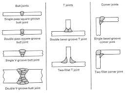
Welding Joint Types: Butt Joints, Lap Joints, Tee Joints & More
Joining Processes
10.5.3 Thermocompression bonding (TCB)
Resistance welding is the method used to join two plain metal work pieces together by running an electrical current through them. The necessary welding heat is generated by the electrical resistance of the metals, by the contact resistance in between them and by the electrical current. No filler metal and no flux are needed. TCB is a special type of resistance welding that can be used to join insulated metal surfaces. The TCB electrode consists of two legs that are connected together at the tip. The electrical current thus runs only through the electrode and generates the welding heat directly at the tip. The generated heat destroys any insulation layers of the metals instantly.
In contrast to resistance welding – where the electrical current generates heat exactly at the welding location – the heat generated from a TCB must flow from the electrode tip to the welding location at the interface of the two metals. As a result, more heat is transferred to the top than to the bottom of the two metals. This, along with the necessary melting point, limits the choice of the joining metals. The process window for TCB is therefore smaller than for resistance welding. An overview to some metal combinations is given in AVIO (2011).
TCB has three main process parameters: welding power (P), welding time (T) and pressure of the tip (P). These parameters are usually kept within a given window, to ensure quality. The off-the-shelf welding equipment controls the process by an adjustable pulse in the current (I), voltage (V) or power (P). The control mode depends on the material configuration, and it is important to differentiate between diffusion bonding and fusion welding. Diffusion bonding (solid-state bonding) occurs at 70 to 80% of the melting points of the work piece metals. Such bonds possess very good shear strength and tenacity, but less desirable peel strength. Fusion welding occurs above the melting points of the work pieces. These bonds have very good shear strength, tenacity and peel strength (Zhou, 2008).
Figure 10.5 illustrates the TCB process schematically. The electrode is placed with defined pressure on top of the work pieces; in this example, a wire is pressed onto a copper pad. The weld is then released with carefully controlled impulse shape, defined energy and time. A solid work surface is crucial for a high-quality weld. The strength of the weld can only be tested with certainty by destruction of the weld, for example by using a peel test. A weld is generated within a few milliseconds to several seconds, depending on the dimensions and materials of the two work pieces. Resistance and thermo-compression welding are typically employed for electrical coils, electric motors and light bulbs. An entire welding cycle takes about 3 to 10 seconds in an automated process set-up. Major companies, currently producing welding control units, welding heads and electrodes, include Miyachi, Avio, Kombitec, Lingl and Resistronic. Figure 10.6 shows the welding spot of a wire on a PCB surface. The shape of the welding electrode can clearly be identified. The wire itself is directly woven into the PET fabric and the PET fabric and the wire insulation around it melt and evaporate during the welding process, thereby welding the wire to the PCB.
10.5. (a, b) TCB weld process.
10.6. Weld of a woven wire onto a PCB (Sefar AG).
Solved A manufacturer has been using two different

MIG vs TIG |
Laser Beam Welding: Working, Equipments, Applications
Welding and Soldering
4 Resistance welding electrodes
Resistance welding electrodes play an important part in the achievement of good and consistent weld quality. The materials used are normally copper alloys, internally water-cooled, which provide a combination of high electrical and thermal conductivity, together with mechanical strength. This is required to withstand the electrode forces and a certain amount of hammering of the electrodes on initial contact. The dimensions of spot welding electrodes are covered by various ISO standards.
Electrode materials for resistance welding are covered by ISO 5182. The highest conductivity class 1 alloys, such as Cu/0.1%Zr, are used for spot welding coated steels and aluminium alloys. Harder, class 2 alloys with a conductivity of 75 to 80% IACS (International Annealed Copper Standard), such as Cu/l%Cr, are used for steels in general. Class 3 alloys, with 30 to 45% IACS, provide additional hardness for spot welding stainless steels and for projection welding dies, although tungsten/30%Cu inserts are also often used in projection welding. Refractory metals such as molybdenum or tungsten are also used for certain applications.
The diameter of the electrode contact face for spot welding should approximate to 5√t">5√t, where t is the single sheet thickness in millimetres (up to 3 mm). This allows a weld of a similar diameter to be produced. In order to maintain weld quality, the electrode contact area and profile should be maintained by periodic electrode dressing or replacement by re-machined electrodes. An electrode dressing tool or form tool should be used where possible for greatest reliability. Automatic dressing equipment can be used in robotic applications. Typically, a few hundred spots for aluminium alloys, a few thousand for coated steels and several thousand for uncoated steels, are possible before electrode maintenance is required.
PETER HOULDCROFT, in Which Process 1990.
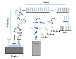
Schematics of the joining process.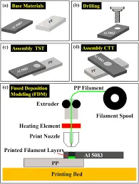
Principle
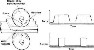
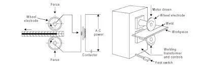
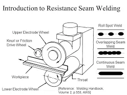
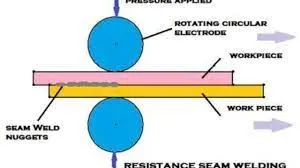
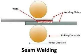
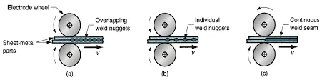
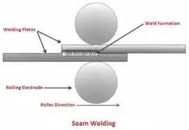
A resistance welding process in which overlapping sheets are gripped between roller electrodes enabling a series of either discontinuous or overlapping spots to be made. The force on the electrodes is sufficient to give good contact at the surface of the sheets and a fused nugget develops at the faying surfaces. Welding current is usually supplied in pulses with rotation being continuous but some use is also made of continuous current. As the previously made nugget provides a shunt path for the welding current a higher current is needed than for spot welding (RSP) of the same thickness material.
Principle of resistance seam welding.
Resistance spot welding process
7.4.11 Resistant Welding
In resistance welding, also called resistance implant welding, current is applied to a conductive heating element or implant placed at the joint interface of the parts being welded. The implant is heated through Joule heating, and the surrounding plastic melts and flows together, forming a weld. Thermoplastics can be welded by this method, which was originally developed for high-performance thermoplastics reinforced with continuous carbon fibers. Joint strengths of thermoplastics can be higher with this welding method than those obtained with adhesive bonding .
Heating elements can be carbon fiber prepregs, woven graphite fabric, or stainless steel foil or mesh. Stainless steel heating elements can be used alone in welding thermoplastics. Stainless steel heating elements introduce foreign material into the joint but are used to minimize any potential for galvanic corrosion and to reduce fiber motion, which has a detrimental effect on joint strength. The heating element comprises the innermost portion of the weld stack (Fig. 7.25) used in resistance welding.
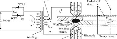
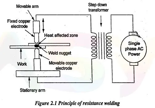
Figure 2.1 Principle of resistance seam welding.
The heating element is sandwiched between the parts to be joined, referred to as the adherends. Thermoplastic materials used include neat thermoplastics and composites such as carbon fibers in a polyetherether ketone, polyarylsulfone, or PEI matrix. An interlayer thermoplastic material melts or softens below the melting point of the adherend, so that adherend degradation is minimized and mechanical performance of the joint is maintained. Insulators on the outermost ends of the weld stack complete the assembly. The weld stack can be autoclaved for consolidation .
To begin the welding cycle, pressure is applied to the weld stack, and electric current is passed through the heating element (Fig. 7.25). Joule heating of the implant causes a rise in temperature; the adjoining thermoplastic material melts (for semicrystalline thermoplastics) or softens (for amorphous thermoplastics) and flows under pressure. Any surface irregularities are smoothed out and molten plastic is squeezed out of the weld interface, removing any interlaminar voids. Intimate contact between the two thermoplastic materials is achieved as thermoplastic molecular interdiffusion (healing) and polymer chain entanglements occur. The power is turned off, allowing cooling and solidification of the weld under pressure.
Laser myths: What fabricators don't know can hurt the process
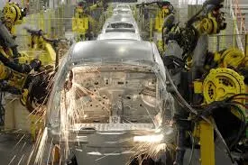
The resistance welding process can be performed at either constant power or constant temperature. In constant power processing, a particular voltage and current is set for the entire weld, and welding occurs for a specified time. This process is not isothermal, and peak temperatures are difficult to predict. In constant temperature resistance welding, sensors, such as thermocouples, are used to monitor the welding process to adjust current and voltage as necessary. The constant temperature process provides more thermal uniformity but is not commonly used .
A three-stage welding cycle is used in resistance welding: a ramp up stage, a peak current stage, and a ramp down stage. Weld cycle times are about 1 min. Processing parameters include power or current applied to the heating element, weld pressure, peak temperature, and dwell time (time held at peak temperature or current).
RESISTANCE WELDING: Spot Welding, Seam Welding, Projection Welding, Resistance Butt Welding, Flash Butt Welding, Percussion Welding, High Frequency Resistance Welding, High Frequency Induction Welding
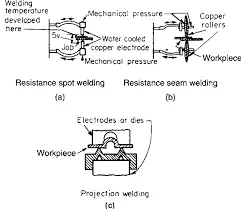
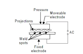
a)-Resistance spot; (b)-resistance seam; (c)-projection welding.
Seam Welding.
RESISTANCE WELDING: Spot Welding, Seam Welding, Projection Welding, Resistance Butt Welding, Flash Butt Welding, Percussion Welding, High Frequency Resistance Welding, High Frequency Induction Welding ~ MECHTECH GURU
Resistance Welding : Principle, Types, Application,
2. RESISTANCE WELDING Resistance Welding (RW) is a group of fusion-welding processes that uses a combination of heat and pressur
Different Types of Resistance Welding
RESISTANCE WELDING
Resistance spot welding process
Welding is a fabrication process that uses high temperatures to melt and fuse parts together. However, it should be noted that pressure can also be used to aid the process or be used exclusively to produce a weld.
According to
RESISTANCE WELDING: Spot Welding, Seam Welding, Projection Welding, Resistance Butt Welding, Flash Butt Welding, Percussion Welding, High Frequency Resistance Welding, High Frequency Induction Welding

RESISTANCE WELDING: Spot Welding, Seam ... "the process of welding doesn't merely bond the two pieces together as in brazing and soldering, instead, it causes the metallic structures of the two pieces to join together and become one through the use of extreme heat and sometimes the addition of other metals or gases."
Welding , Hardfacing , Cladding and Cutting of metals: Resistance Welding Process
It is usually distinguished from lower temperature metal fusing techniques like brazing or soldering, which do not usually melt the base metal.
Welding usually also involves the use of something called a filler material, or a consumable. This, as the name suggests, is used to provide a "filler" or pool of molten material that helps facilitate the formation of a strong link between the base metals.
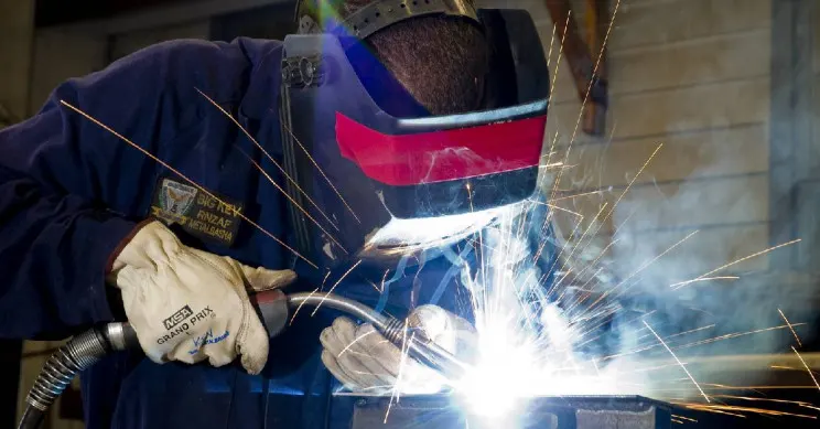
Most welding processes will also require some form of shielding to protect both the main components and filler from being oxidized during the process.
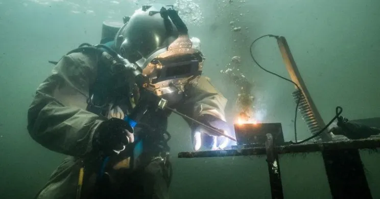
Welding can be performed using various energy sources. Examples include, a gas flame (powered by a chemical like acetylene), an electric arc (electrical), laser, an electron beam, friction, and ultrasound. There are various welding techniques that fit open air, underwater, and even space settings.
What are the types of welding?
Welding has been used in metallurgy for millennia. Although, forge welding, in which blacksmiths join iron and steel by heating and hammering was the only viable technique for a while. This all changed in the 19th century when more advanced methods like arc-welding and oxyfuel welding were developed.
Welding equipment review platform Welder Station lists some of the most common welding processes as:
- MIG Welding - Gas Metal Arc Welding (GMAW)
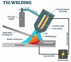
- TIG Welding - Gas Tungsten Arc Welding (GTAW)
- Stick Welding - Shielded Metal Arc Welding (SMAW)
- Flux Welding - Cored Arc Welding (FCAW)
- Energy Beam Welding (EBW)
- Atomic Hydrogen Welding (AHW)
- Gas Tungsten-Arc Welding
- Plasma Arc Welding
-
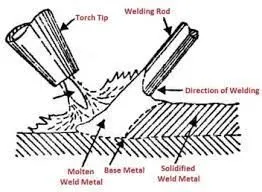
a) Schematic diagram of GTA spot welding assisted with ultrasound;
a) Schematic diagram of GTA spot welding assisted with ultrasound
What are the different types of welding machines?
There are quite a few different types of welding machines knocking around. These machines generate heat that melts metal parts so they can be joined. However, there isn't a single welding machine that is suitable for all welding purposes.
Larger welding machines tend to be found in industrial sites like factories, while smaller ones are more ideal for domestic or amateur purposes.
According to Welding Hub, there are five main types of welding machines. These are:
- Mig (metal inert gas) welding machines.
- Thyristor Control Mig welding machines.
- Tig welding machines.
- Spot welding machines.
- Shielded metal arc welding machines.
MIG welding machines are some of the best around for most types of welding purposes whether at home or in a factory. They tend to be able to handle various metals including mild steel, stainless steel, and even aluminum.
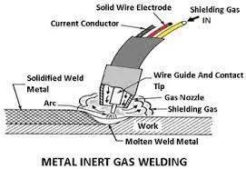
MIG welding is an arc welding process where a continuous solid wire electrode is fed through a welding gun into the weld pool, joining the two base materials together. A shielding gas sent through the welding gun protects the weld pool from contamination.
MIG welding is usually pretty fast and provides a long arc time even when the electrodes are not fully charged.
Thyristor Type MIG welding machines are generally best for fixing objects or mounting them on a suitable surface. These machines tend to be of good quality and will last a very long time.
Such welding machines produce a small amount of spark, which makes them easy to control. These machines are best suited for welding solid core and flux materials. They can handle mild steel, low carbon steel, alloy steel, etc.
TIG welding machines are more specialized than the others and provide a clean and pure weld without splatter, sparks, or fumes. These machines can handle stainless steel, brass, gold, magnesium, aluminum, copper, and nickel alloys.
TIG welding machines are generally not suitable for fieldwork but are great for repairing damaging parts.
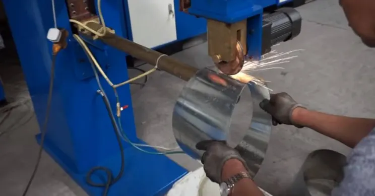
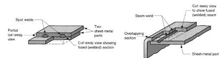
Spot welding machines tend to be used to join overlaps between things like sheets of steel. To do this, metal sheets are usually protected using a pair of electrodes by passing a current through them.
Spot welders have many great advantages over others like effective power utilization, high manufacture rates, simple automation, etc. These kinds of welding machines tend to be most commonly found in the motor vehicle industry. They are also generally a lot cheaper than their alternatives.
Shielded metal arc welding, also known as stick welding, uses an electric current flowing from a gap between metal and welding stick. In this type of welding, electric current is used to create an arc between the base material and the filler rod (also called an electrode rod). The filler rod is covered with a flux that prevents oxidation and contamination by producing carbon dioxide gas during the welding process.
What is the strongest type of weld?
To answer this question is not as simple as it may first appear. The best weld depends on the base material in question and its intended use. From TIG to plasma arc welding, each technique has its own unique advantages and disadvantages over the others.
According to Crom Weld, the strongest type of weld could be stick welding: "if pure strength that counts and the thickness of the material that can be welded, then stick welding is the winner. As we said, the stick method is the only one capable of welding cast iron, additionally, it also works on dirty materials and under harsh weather conditions."
But that doesn't necessarily mean stick welding is the best choice for all scenarios. MIG can be applied to a wider selection of metals of varying thickness, while TIG welding produces the highest quality welds, especially when it comes to thin metals."
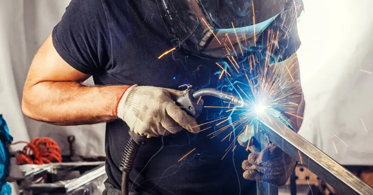
It also depends on the metal you wish to weld. For example, welding aluminum can be tricky as it is a fairly soft metal which can't cope with too much heat. For this reason, there are only two viable welding techniques that can be used with aluminum, MIG welding and TIG welding.
Of these two techniques, TIG welding is widely considered to be the go to technique for best results.
Stainless steel welding, on the other hand, is different, as it's a much beefier metal when compared to aluminum. For this reason, it can take a lot more punishment before compromising its strength. But, which welding technique provides the strongest weld depends on the thickness of the material.
MIG welding is generally considered to be the best technique for most steel applications. When it comes to thicker steel sheets, many bow down before the superiority of stick and flux welding.
If the steel is mild and stainless, TIG welding and MIG welding can be used without any real issue.
How do you choose the right welding gloves?
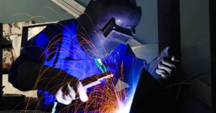
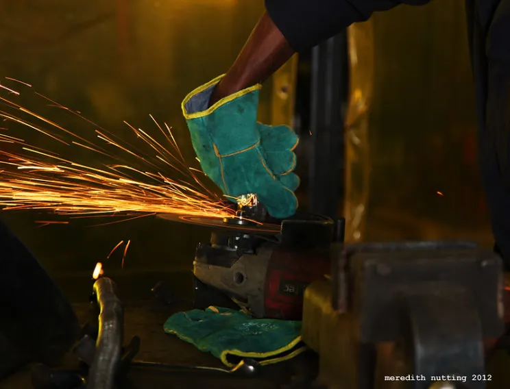
Apart from a decent quality welding mask and welding machine, another essential piece of welding gear are the gloves. As their job is to protect your precious yet fragile human hands from potentially serious burns, choosing a good quality pair is absolutely essential.
But there is no one-size-fits-all when it comes to welding gloves. Factors like the type of welding you'll be using them for and how much dexterity you're going to need are all considerations.
The type of welding you'll be using will produce different amounts of sparks and other hazards. MIG welding, for example, tends to produce a lot of sparks that need to be shielded against and cleaned up afterward.
Gloves also come in a variety of materials too. For most users, leather is the most preferred kind as it is durable, non-conductive, and is great at dissipating heat.
But leather can be made from various types of animal skins. Some common examples include:
- Goatskin - This kind of leather offers unparalleled abrasion and tensile strength while remaining soft and supple. This is ideal for TIG welding where you need the maximum amount of dexterity possible.
- Horsehide - Horsehide is tough a durable, yet remain comfortable. While less popular, as leather gloves go, it is also great for TIG welding.
- Pigskin - Pig leather is tough and performs very well in wet and oily work environments. This kind of leather is great for TIG, MIG, and stick welding, among others.
- Cowhide - Cow leather is one of the most common kinds of leather. It is very durable and comfortable and is usually preferred for stick and MIG welding.
- Deerskin - A soft and flexible leather, the freedom of movement it provides makes it another great choice for TIG welding.
- Elkskin - Elk leather tends to not harden as quickly as cowhide when exposed to heat. Elkskin is another great choice for MIG welding due to the high amount of heat it gives off.
What is the best welder for a beginner?
If you are new to the world of welding, some techniques are much easier to pick up than others. MIG welding, for example, is widely considered to be the easiest to pick up and run with. But why?
Joining includes welding, brazing, soldering, adhesive bonding of materials. • They produce permanent joint between the pa
Joining Processes and Equipment
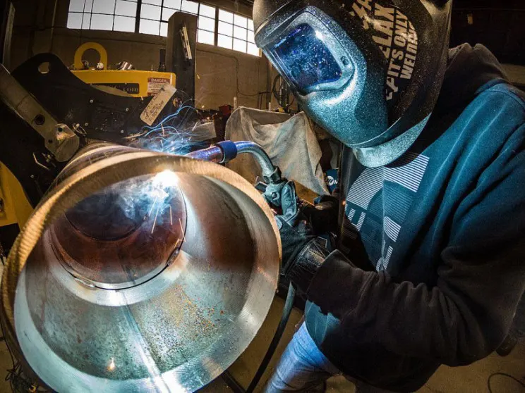
MIG welding has a high adjustability of power output. It also produces very clean welds compared to most other techniques. It is also great as it is usually pretty quick, a feature loved by beginners and masters alike.
Other techniques also exist if your budget allows. You could consider getting yourself something called a hybrid welder. This lets you try multiple techniques with one tool. Yet despite this, many practicing welders endorse the simplicity and reliability of MIG welding for learning the ropes.
What non-industrial things can welding be used for?
While welding is of great utility in many industries around the world, it can be used for other things too. One example is in the world of art.
If you ever watched the timeless classic animated film, The Iron Giant, Dean McCoppin did just that.

Tracing our steps back into real world, many artists are using techniques mentioned above to produce magnificent works of art. Of those artists out there who use welding to produce their work, one interesting example is Chain Breaker Welding.