Week 2 Bevel Gear Challenge
Objective
To perform a Static analysis with a grid dependency test for the Bevel gear with a global mesh size of 6,5 and 4 mm and to compare the results using Ansys Workbench.
Introduction
- Grid dependency test is to investigate how the solution depends on the grid size by running the simulation with refined mesh that is finer the mesh, higher is the accuracy of the result but with additional cost on computation time and computational power. Since solutions are interpolated at the nodes to get an approximate result, the higher the number of nodes and elements higher is the more computational time and power required to complete the simulation.
- So, the grid dependency test helps in determining optimal mesh size where the accurate result could be obtained keeping in the mind the cost of time and power. Since the result obtained are approximate,
- Refining mesh further would result in negligible percent change is the result but only increase the computational cost.
Procedure
- A new Ansys file was opened and the static structural model was dragged onto the project window.
- The given cad model of a bevel gear was inserted into the geometry tab. The model was modified in the geometry tab to reduce the simulation time.
- After modifying the geometry, Select the model tab for setting up the meshing, defining contacts, and other analysis setups.
- When the model tab gets opened rename the parts as pinion and gear and sign the selected material from the sub-option.
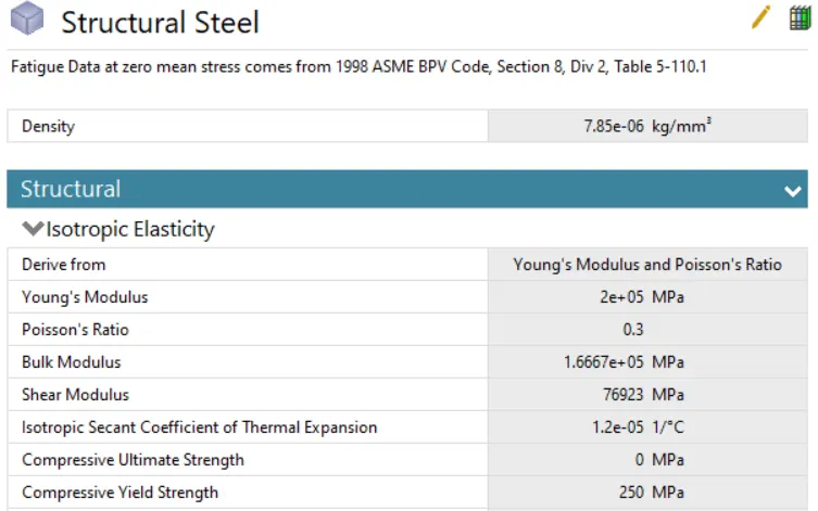
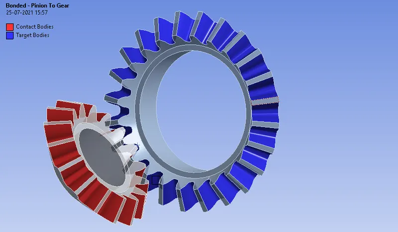
- Now go to the connection option and from there right-click contact region>Rename based on the definition. By this, some automatic contacts get detected while importing but we need to select all the faces that will be in contact throughout the simulation. So, the selection was done as per the image shown below.
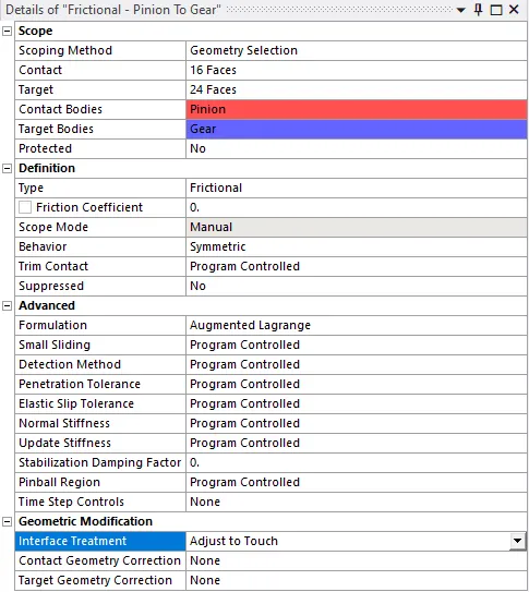
- Also, other details of contacts were changed as shown below.
- The joints are defined by right-clicking the connections>Insert>Joint. The joint definition made for the gear is shown below.
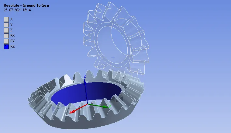
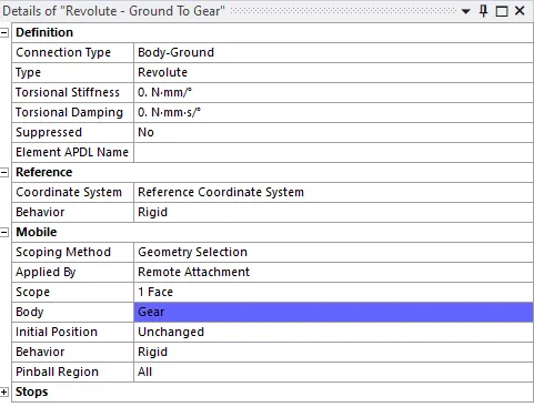
- Also, check the coordinate system matched with the axis of rotation. If any correction is needed, it can be changed by Reference>Reference coordinate system.
- Similarly the joint for pinion was also created.
- The simulation was run using six steps and the geometry was rotated to an angle of 120 degrees by incrementing 20 degrees in each step. The resistance of 100N-mm was on the big gear.
- From the analysis option, assign the number of steps as six then selects all the six steps by pressing the control key. After that changes were made as shown below.
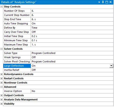
- Now joint loads were assigned by right-clicking static structural>Insert>Joint load.
- The joint load definition of gear was given by providing the moment.
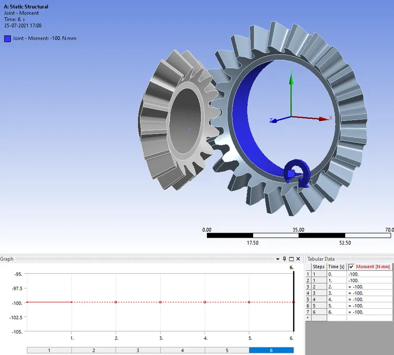
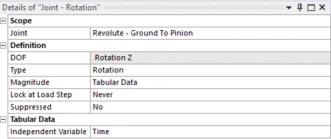
- Similarly, a joint load definition for the pinion was assigned using rotation.
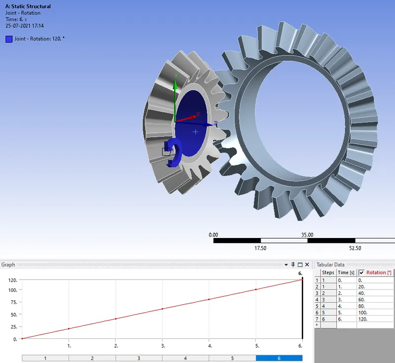
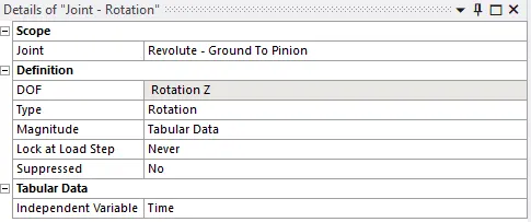
- The direction of the rotation of the gear and pinion showed be checked and if it's in the same direction it should be changed either by changing the coordination of the gear or by changing the sign of the magnitude value.
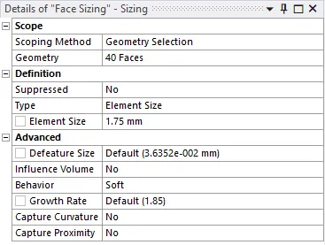
- The model has meshed initially with the default setting. So when it meshed in that way it gave a coarse mesh because some of the uniform surfaces in the gear made the teeth region also coarse. Since the stress will be induced more onto this area it would be recommendable to make those regions finer and also it will lead to some convergence issues. So to prevent this we can use face sizing. This can be done by right-clicking the mesh option>insert>sizing.
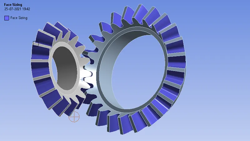
- The selection was mode to the teeth surfaces.
- An element size of 1.75mm was given to the teeth region and for the entire model it meshed with 6mm,5mm and 4mm separately to compare the result.
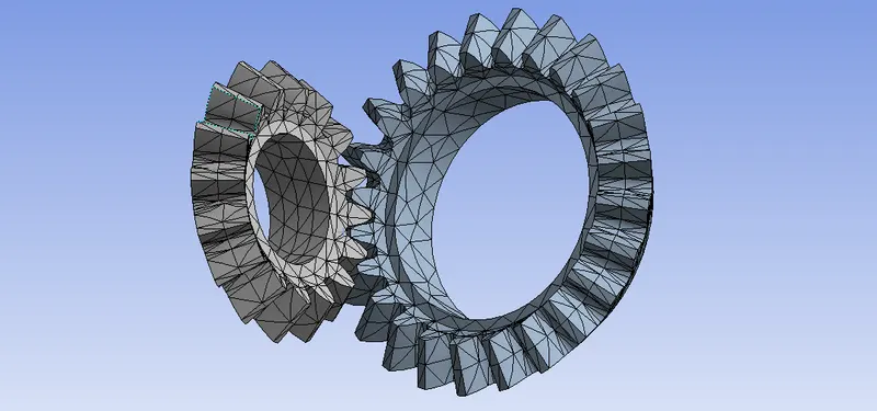
- From the solution tab, the equivalent stress, total deformation, equivalent strain energies were requested.
Results
- Static analysis with a grid dependency test for the Bevel gear simulation with a global mesh size of 6,5 and 4 mm was performed and compared the results.
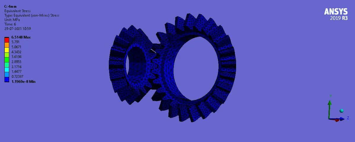
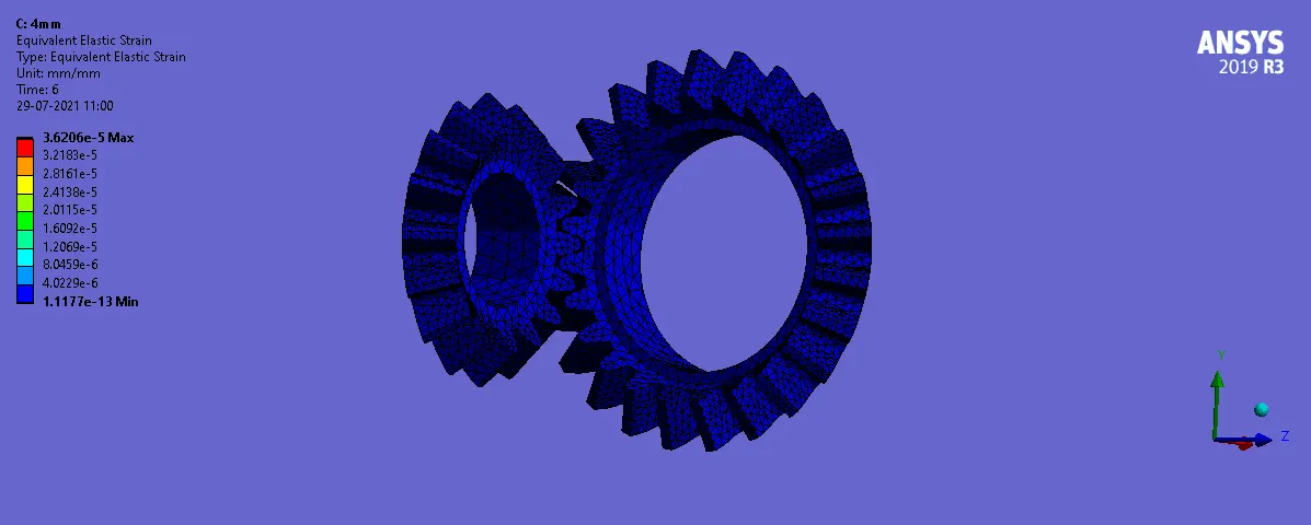
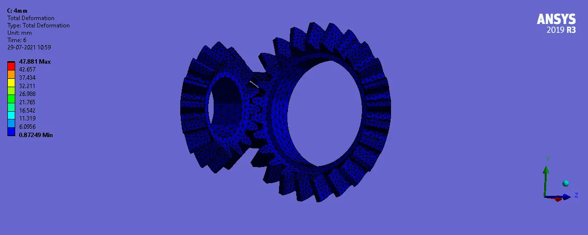
- Below results shows the outputs for the bevel gear meshed with 4mm mesh size.
Equivalent stress
Equivalent elastic strain
Total deformation
- Similarly, all the output for other mesh sizes were found out and tabulated to compare the result. The tabulated results are sown below.
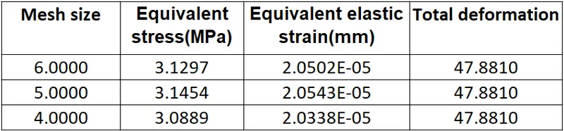
- The total deformation for the three mesh sizes remains the same.
- The equivalent stress and equivalent strain for the mesh with 5mm were found to be more and the mesh size with 4mm has the least value.
- We can observe that as the mesh is refined from e.g 5mm to 4mm we achieve a better approximation of the result for equivalent elastic strain and equivalent stress. however, performing the simulation with further refining the mesh would result in a very close approximation of the result but with a very negligible change in the result with an additional on the computational power and time.
Conclusion
- From the results, we can observe that when the mesh is refined the equivalent stress and strains values changes and we may get the high accurate result when the mesh density is high, assuming no singularities are present. But this process will take a long run time and also require a large amount of computer memory. Basically, a grid dependency test is done with a coarse mesh and is refined in each run till the result do not change significantly. When the mesh size equals zero, the approximate solution becomes equal to the actual solution. Since this won't be that possible, so our aim will be to find out an optimum mesh size for a particular simulation.
.............................................................................................................................................................................................................
File: https://drive.google.com/drive/folders/1nkILHk4Vbnjfx-VUN7ojhIF1sf8uXDbc?usp=sharing