Week 2 Bevel Gear Challenge
OBJECTIVE
- Explain the process of the Grid Dependency test
- Setup a case of bevel gear simulation using given sets of input
- Perform a grid-dependent test for the bevel gear using different mesh element sizes of 6mm, 5mm, and 4mm.
- Provide inferences based on the results.
GRID DEPENDENCY TEST
- We know that FEA is a numerical simulation approach. It is based on the approximation of results from adjacent elements and nodes. So more refined the mesh, the more accurate results.
- Ideally, the mesh size that tends to zero yields the perfect result but that is not practically possible. Hence we use different mesh sizes to achieve the best result possible.
- But we don't have any specific element size defined, that our results will be correct at the given mesh size. So usually the process of meshing starts with trial and error.
- We start with a coarse mesh and then proceed towards finer mesh. So when the variation in the result is minimal or almost identical, the simulation is said to have achieved grid independence. This means that the results of the simulation will remain the same even if we refine the mesh further.
- This whole process is called the Grid-Dependency test.
- For any simulation, at least 2 to 3 mesh sizes are checked before finalizing the results based on the grid dependency test
PROCEDURE
Step 1 - Engineering Data
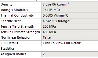
- Add the required materials for the analysis from the engineering database.
- Structural Steel
Step 2 - Setting up the geometry
- Import the given geometry to Spaceclaim.
- Check if the geometry is perfect or not
Step 3 - Meshing
- Assign global mesh size 6 mm (or 5 or 4mm).
- Also select the contact surface and make a face sizing. Mesh -> Sizing -> select surfaces -> 1.5 mm
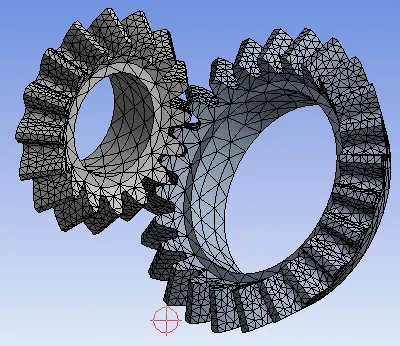
- Check mesh quality

Step 4 - Connection
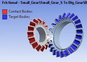
- Contact - surface to surface frictional contact is defined for the motion between 2 gears.
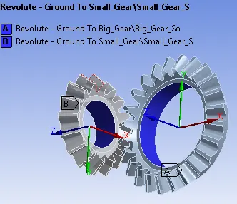
- Joints - Revolute joint is created for both the gear using Inset -> Joint -> Revolute
Step 5 - Boundary conditions
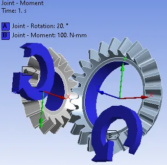
- Here since we require the motion of gears, the movement assigned to them should be in opposite directions.
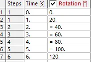
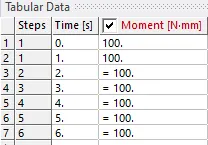
- Assign the rotation in small gear (total 120 degrees) and a moment of 100 N-mm in the other as shown below. The inputs are given in 6 steps.
Step 6 - Analysis settings
Step 7 - Output requests
- Make a request for the deformation, stress, strain, contact pressure
Step 8 - Results
- Review the results of stress and deformation and check the animation.
- Based on the confirmation of the correctness of analysis, review, and extract other relevant results.
RESULTS
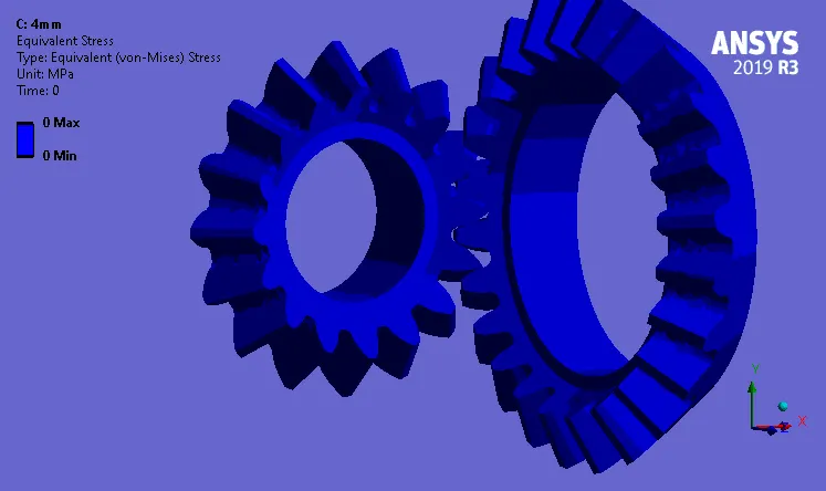
CASE 1 - Mesh Size 6mm
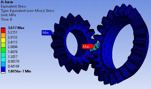
- Stress
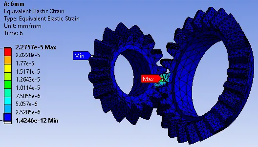
- Strain
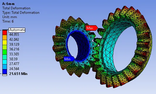
- Deformation
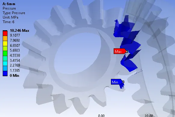
- Contact pressure
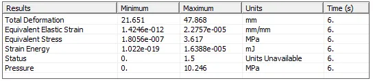
- Result summary
Case 2 - Mesh Size 5mm
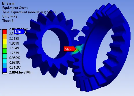
- Stress
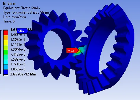
- Strain
- Deformation
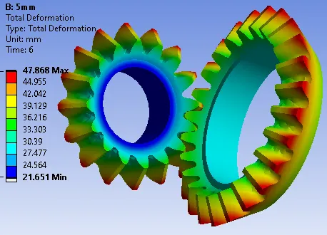
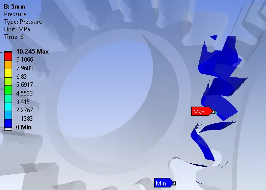
- Contact pressure
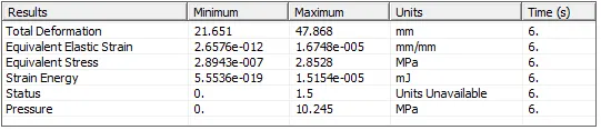
- Result summary
Case 3 - Mesh size 4mm
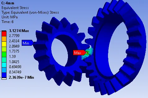
- Stress
- Strain
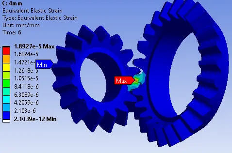
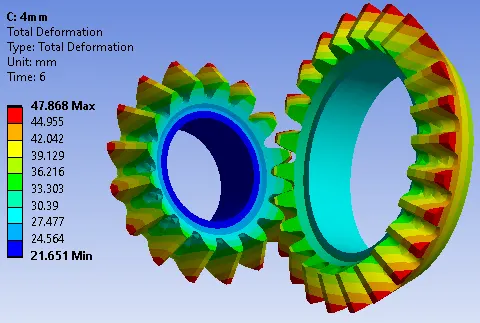
- Deformation
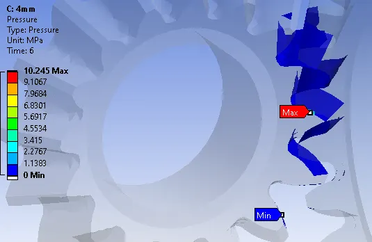
- Contact pressure
- Result summary
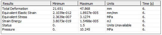
Based on the above-extracted results, a detailed table report is as below.
| Mesh Size = 6mm | Mesh size = 5mm | Mesh size = 4mm | |
| Stress (MPa) |
3.617 | 2.85128 | 3.1274 |
| Strain | 2.2757e-5 | 1.6748e-5 | 1.8927e-5 |
| Deformation (mm) |
47.868 | 47.868 | 47.868 |
| Contact Pressure (MPa) |
10.246 | 10.245 | 10.245 |
CONCLUSION
We performed a simple static structural simulation for bevel gear. The results are discussed in the final table in the previous section. We see a little change in the values of stress and strain and this can further be refined with more refined mesh. Although we see the contact pressure and deformation have achieved grid independence and these results will no longer be affected by mesh.