Different Connectors in Hypermesh
Objective
Create a connector and Attach the various parts of the given model
- Right_Rail_2 & Front_truss_1:- Seam-Quad (angled+capped+L)
- Left_Rail_2 & Front_truss_1:- Quad elements
- Front_truss_2, Front_truss_1 & Right_Rail_1:- Spot weldwith 3 Layers and 5 mm Diameter
- Front_truss_2, Front_truss_1 & Left_Rail_1:- Hexa (Adhesive)
- Rear_truss_2 & Right_Rail_2:- Bolt Connector
- Rear_truss_2 & Left_Rail_2:- Bolt Connector
- Right_Rail_1 & Right_Rail_2:- Spot-weld with Rigid Elements
- Left_Rail_1 & Left_Rail_2:- Spot-weld withSpring Elements
- Rest all the component left Join them with suitable connectors
Procedure:
- Open the model
- Perform a geometric cleanup where necessary. Toggle unwanted edges and split large surfaces as shown in the figure.
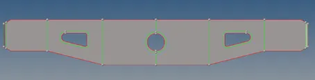
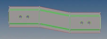
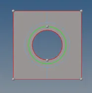
Fig – Geometry Cleanup
- Mesh all the components using 2D -> Automesh. Element size = 5mm and element type quad (preferable) or mixed.
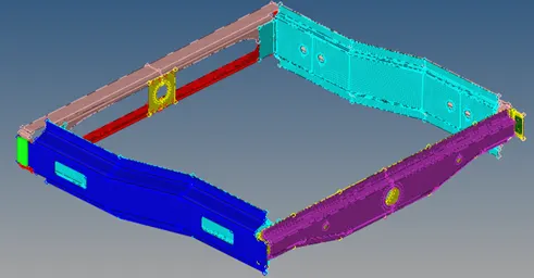
Fig – Meshed Model
Connectors.
Note: After creating any connectors check for the mesh. If distorted then remesh that section
- Right_Rail_2 & Front_truss_1:- Seam-Quad (angled+capped+L)
- Bring Right Rail 2 and Front truss 1 on-screen.
- Select 2D -> connectors -> Seam -> Select nodes ->spacing = 5 -> select components -> tolerance =10 -> type = Seam quad (angled + capped + L) -> imprint -> create
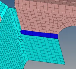
- Left_Rail_2 & Front_truss_1:- Quad elements
- Bring Left Rail 2 and Front truss 1 on screen.
- Select 2D -> connectors -> Seam -> Select nodes ->spacing = 5 -> select components -> type = Quads -> imprint -> create
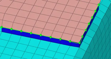
- Front_truss_2, Front_truss_1 & Right_Rail_1:- Spot weldwith 3 Layers and 5 mm Diameter
- Bring Right Rail 1, Front truss 2, and Front truss 1 on screen.
- Select 2D -> connectors -> spot -> select node -> select comp -> layer =3 -> type = weld -> dia = 5mm -> tolerance = 10
- Repeat the process for the remaining side.
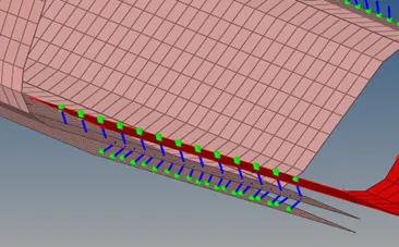
- Front_truss_2, Front_truss_1 & Left_Rail_1:- Hexa (Adhesive)
- Bring Left Rail 1, Front truss 2 on screen.
- Select 2D -> connectors -> Seam -> Select nodes ->spacing = 5 -> select components -> tolerance =10 -> type = hexa (adhesive) -> imprint -> create
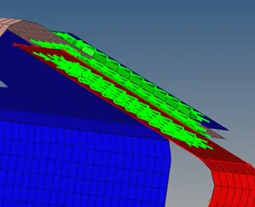
- Rear_truss_2 & Right_Rail_2:- Bolt Connector & 6. Rear_truss_2 & Left_Rail_2:- Bolt Connector
- Bring Rear truss 2 & Right Rail 2 on screen.
- Select 2D -> Connectors -> Bolt -> select nodes -> select coms -> type = bolt (general) -> select hole if none -> create
- Repeat the process for Rear truss 2 and left rail 2
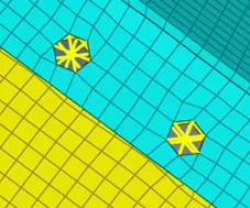
- Right_Rail_1 & Right_Rail_2:- Spot-weld with Rigid Elements
- Bring Right Rail 1 & Right Rail 2 on screen.
- Select 2D -> connectors -> spot -> select nodes -> select comp -> layer =3 -> type = rigid -> dia = 5mm -> tolerance = 10
- Repeat the process on another side
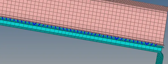
- Left_Rail_1 & Left_Rail_2:- Spot-weld withSpring Elements
- Bring Left Rail 1 & Left Rail 2 on screen.
- Select 2D -> connectors -> spot -> select nodes -> select comp -> layer =3 -> type = Spring -> dia = 5mm -> tolerance = 10
- Repeat the process on another side
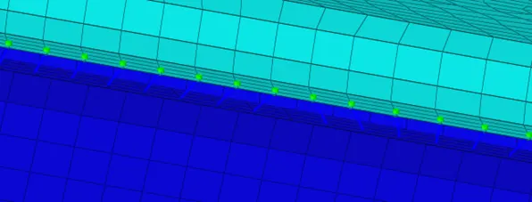
- Front_truss_2, Front_truss_1 & Reinf_Plate :- Spot weld – Rigid element
- Bring Front truss 1 & Reinf plate on screen.
- Select 2D -> connectors -> spot -> select nodes -> select comp -> layer =3 -> type = rigid -> dia = 5mm -> tolerance = 10
- Repeat the process on another side
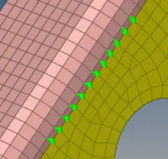
- Left_Rail_1 & Rear_truss_2:- Adhesive
- Bring Left Rail 1 & Rear truss 2 on screen.
- Select 2D -> connectors -> area -> select element -> select comp -> type = adhesive -> tolerance = 10 -> create
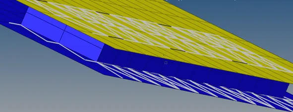
- Left_Rail_2 & Front_truss_2:- adhesive
- Bring Left Rail 2 & Front truss 2 on screen.
- Select 2D -> connectors -> area -> select element -> select comp -> type = adhesive -> tolerance = 10 -> create
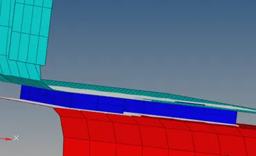
- Right_Rail_1 & Rear_truss_2:- Seam Adhesive Hexa
- Bring Right rail1 & rear truss 2 on-screen.
- Select 2D -> connectors -> Seam -> Select nodes ->spacing = 5 -> select components -> tolerance =10 -> type = hexa (adhesive) -> imprint -> create
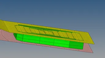
- Right_Rail_2 & Front_truss_1:- Spot weld – rigid element
- Bring Front truss 1 & Right Rail 2 on screen.
- Select 2D -> connectors -> spot -> select nodes -> select comp -> layer =3 -> type = rigid -> dia = 5mm -> tolerance = 10
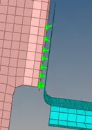
- Rear_truss_1 & Rear_truss_2:- Spot Weld with 3 layer and 5mm dia
- Bring Rear truss 1 & Rear truss 2 on screen.
- Select 2D -> connectors -> spot -> select node -> select comp -> layer =3 -> type = weld -> dia = 5mm -> tolerance = 10
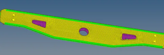
Conclusion
In this challenge, we got to learn about different connectors and the procedure to create them.
We made use of different connectors like seam, spot, adhesives, and bolts.