Week 2 Bevel Gear Challenge
Aim:
The aim of this project is to conduct a grid dependency test for a bevel gear model using 4mm, 5mm, and 6mm mesh size. This project also compares the results for 3 mesh cases.
Grid Dependency Test:
It is known that finer mesh gives more accurate results compared to coarse mesh but at the cost of computational time and requirements. This brings us to the question as what is the tolerance of the mesh or grid size for reasonably accurate predictions. This lies in grid dependence study or mesh refinement study. A series of results are analysed with at least 3 levels of mesh sizes- Coarse, medium, and fine are generated. It is based on reducing the approximation errors to zero and thereby providing grid-independent results. This means that the solution will not be affected by further refinement of the mesh size.
Model Setup:
- Static structural analysis was set up and a CAD model of bevel geometry was imported.
- The contact was defined between teeth of two gears since this is the area which will contact in motion. The contact was frictional with 0 coefficient of friction, augmented Lagrange formulation.
- The revolute joints were defined for two gears in the z-direction.
- The analysis was set up for 6-time steps with an interval of 0.1, a minimum of 0.05 and a maximum of 0.2 seconds. The large deflection option was ON.
- The big gear was given a joint load with rotation in the anticlockwise direction of magnitude defined in table 1:
- The small gear was given a moment of 100N-mm throughout the simulation.
| Time Step | Angle |
| 0 | 0 |
| 1 | 20 |
| 2 | 40 |
| 3 | 60 |
| 4 | 80 |
| 5 | 100 |
| 6 | 120 |
Table 1: Big gear rotation magnitude
Mesh: The mesh sizes were varied for three cases and their corresponding nodes and element sizes are given below in table 2:
| Mesh Size | Nodes | Elements |
| 4mm | 23441 | 12520 |
| 5mm | 22649 | 12044 |
| 6mm | 22638 | 12087 |
Results:
The total deformation, stress, and strain results for 4mm mesh are given in images 1,2,3:
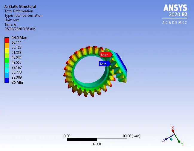
Image 1: Total deformation for 4mm mesh size.
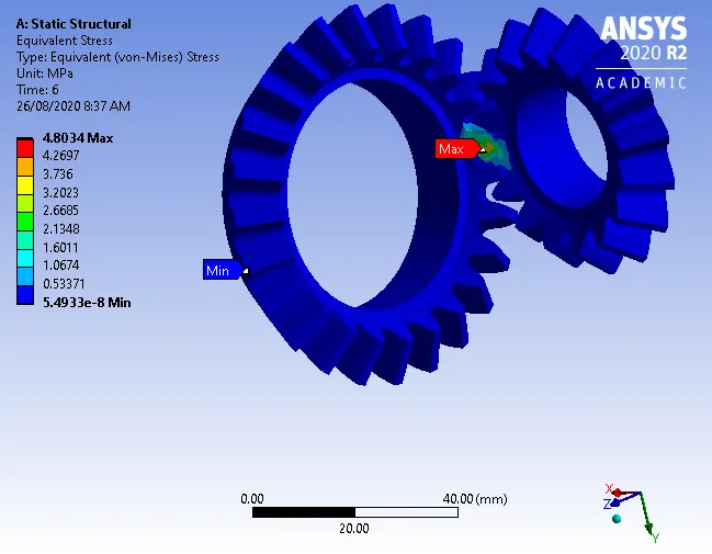
Image 2: Stress in gear for 4mm mesh size.
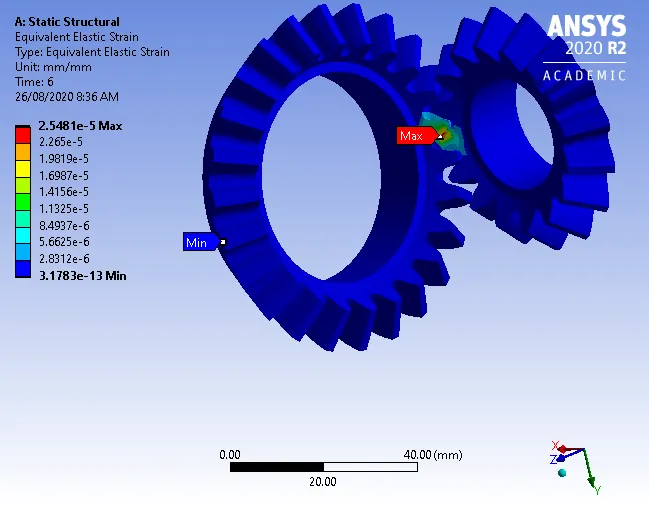
Image 3: Strain in gears for 4mm mesh size.
The total deformation, stress, and strain results for 5mm mesh are given in images 4,5,6:
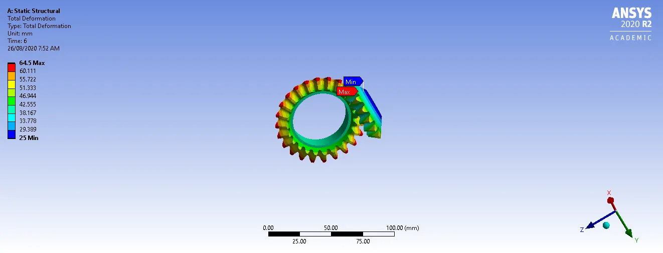
Image 4: Total deformation for 5mm mesh size.
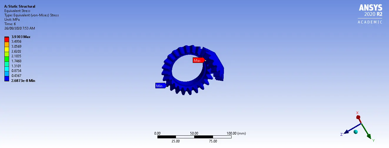
Image 5: Stress in gear for 5mm mesh size.
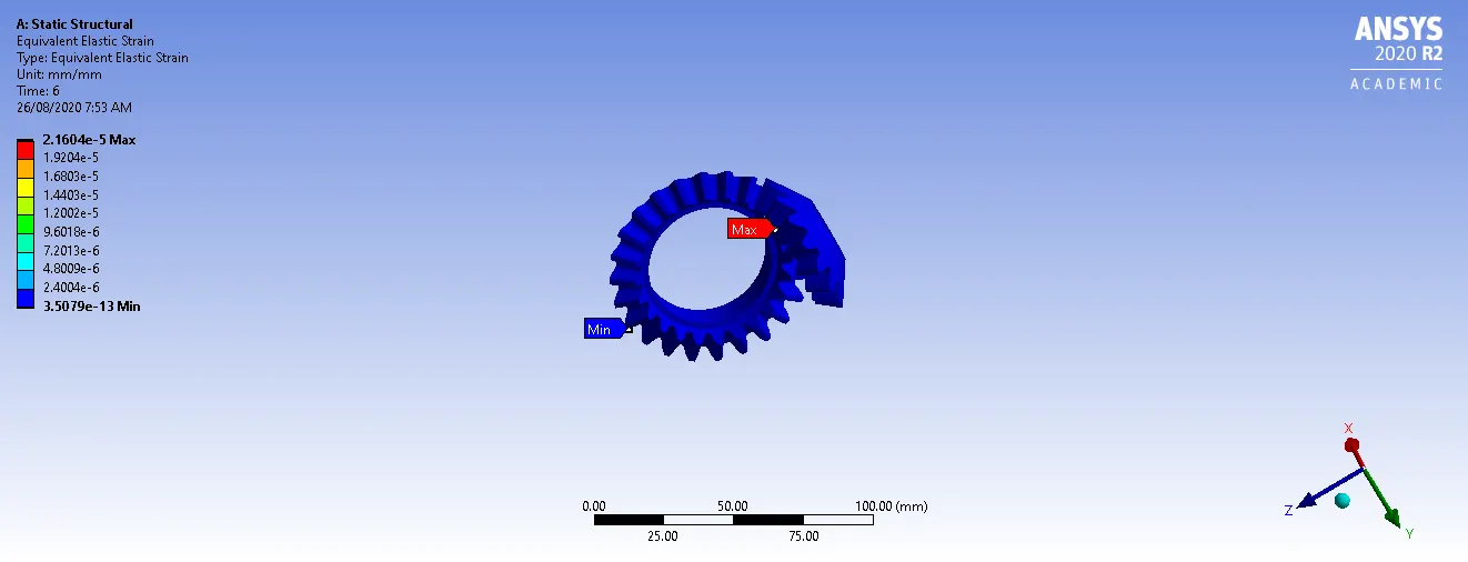
Image 6: Strain in gears for 5mm mesh size.
The total deformation, stress, and strain results for 6mm mesh are given in images 7,8,9:
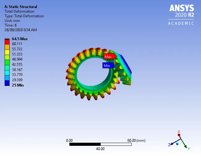
Image 7: Total deformation for 6mm mesh size.
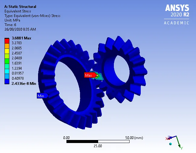
Image 8: Stress in gear for 6mm mesh size.
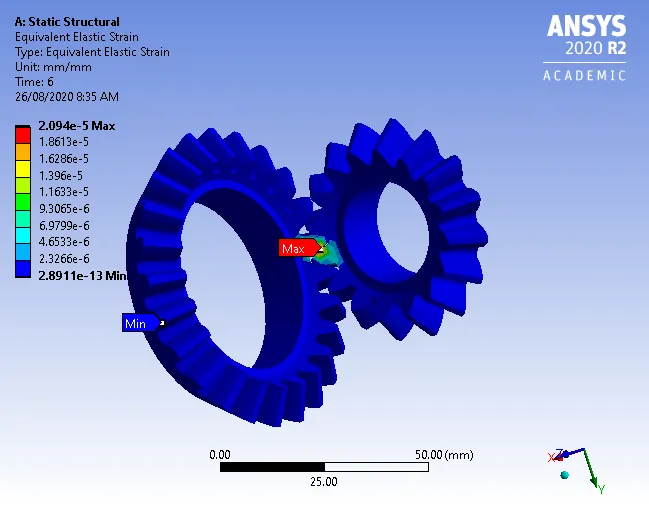
Image 9: Strain in gears for 6mm mesh size.
Conclusions:
The results are compared in table 3:
| Mesh Size | Total deformation (mm) | Stress(MPa) | Strain |
| 4mm | 64.5 | 4.0834 | 2.5481e-5 |
| 5mm | 64.5 | 3.9303 | 2.1604e-5 |
| 6mm | 64.5 | 3.6881 | 2.094e-5 |
As we can see the results are increasing as the refinement of the mesh is finer. This implies that the mesh can be more refined to get more precise results. When the stress jumps of the results are under an acceptable limit the model is said to be mesh independent or grid-independent.