Week 2 Bevel Gear Challenge
BEVEL GEAR
OBJECTIVE
To conduct static structural analysis for evaluating the equivalent stress, equivalent elastic strain and total deformation in bevel gears for different global mesh sizes such as 6 mm, 5 mm and 4 mm using grid dependency test.
DESCRITPION ABOUT GRID DEPENDECY TEST
In finite element analysis, the body is discretized to several parts denoted by number of elements. The nodes are those points where the adjacent elements link each other. The extent of discretization of the entire body subjected to analysis has a critical role in the accuracy of the intended analysis results. This discretization is termed as meshing in finite element analysis. Finer the mesh, higher would be the accuracy. The coarser the mesh size, lesser would be the accuracy. The mesh size is a user defined property. Therefore, the accuracy is dependent on the mesh size and solely depends on the user defined input. For every analysis, the accuracy of the results should be checked by changing the mesh size for coarse to fine. While refining the mesh size from coarser to fine, at some point of smaller mesh size, the change in the accuracy between the succeeding mesh sizes will be very less and from there on which, the further refinement of mesh size will not cause any change in the result value. This will be the most accurate solution compared to coarser mesh size. These kind of test in finite element analysis in search for most accurate solution independent of grid or mesh size is termed as grid dependency test.
The main use of grid dependency test is to find the most accurate solution converged to a specific value that never changes beyond a certain limit by refining and reducing the mesh size. Another important factor would be the analysis time, Coarser the mesh, lesser will be the time taken for running the analysis. Coarser mesh size helps to check if all constraints and steps are correct by taking less time.
METHODOLOGY
The model of bevel gears was imported to the ansys workbench (See Fig. 1). Three separate analyses were conducted using structural steel for three different global sizes such as 6 mm, 5 mm and 4 mm using parametrical study. The material properties of structural steel that was assigned to two bevel gears are shown in Fig. 2. A frictional contact has been established by selecting 40 faces on the bevel gear teeths. The behaviour of the contact was set to symmetric. The formulation was Augmented Lagrange. Interface treatment was ‘Adjust to touch’. Revolute joints were assigned to two bevel gears with body to ground connection type and revolute type by selecting the internal faces of bevel gears. The face mesh was set to 1.75 mm by selecting the 40 faces on the gear teeths. The type of mesh was tetrahedral mesh. The global mesh size was given a parametrical study. Therefore, the global mesh size was set to 6 mm initially. The meshed bevel gears are shown in Fig. 3. Small gear was given rotation in six steps to rotate from 0 deg to 120 deg. A moment of 100 Nmm was given to big gear at all time steps. Care was given to rotate the big gear in anti-clockwise rotation whereas the small gear to clockwise rotation. The analysis settings comprise of 6 steps with auto time stepping on defined by time steps. The initial time step, minimum time step and maximum time step were 0.2s, 0.0005s and 1s respectively. Large deflection was turned on in the analysis settings. The equivalent stress, total deformation, equivalent elastic strain are found out by running the analysis.
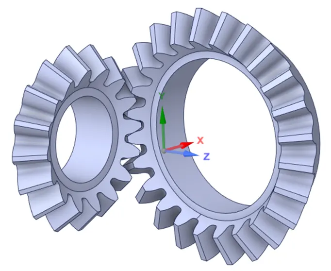
Fig. 1 Imported model of Bevel gears
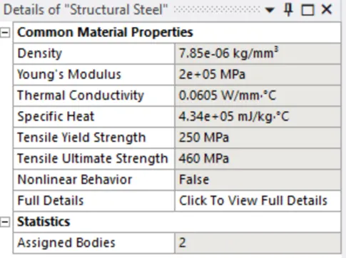
Fig. 2 Properties of structural steel
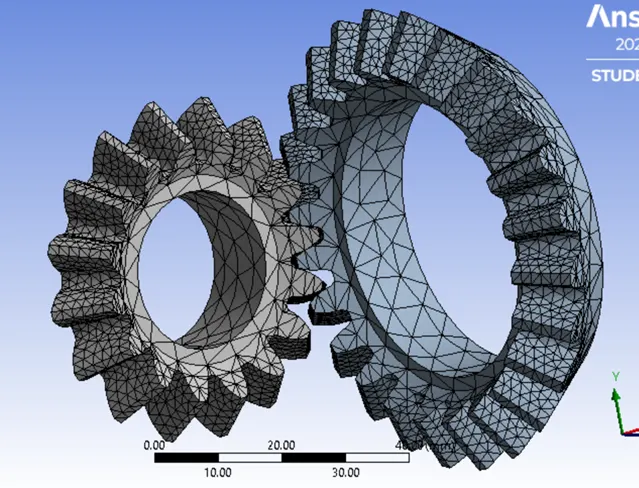
Fig.3 Meshed model
RESULTS AND DISCUSSION
The total deformation, equivalent von mises stress and equivalent elastic strain were evaluated. Table 1 compares the results for three different materials. The total deformation was 47.873 mm for all cases since the gears were symmetrical and set to rotate at the fixed rotational angle from 0° to 120° in six steps. The von mises stress increased from 3.8158 MPa to 3.8999 MPa when mesh size was reduced from 6mm to 5mm and reduced to 3.6144 MPa at 4 mm mesh size. Similarly, the maximum von mises stress over time was 4.636 MPa, 5.2187 MPa and 4.9843 MPa. These results of von mises show that the solution is not converged to an accurate value. There is an abrupt change in the value that depends on the mesh size. In the case of equivalent elastic strain, there is an increase of 0.47E-05 elastic strain when the mesh size was reduced from 6mm to 5mm. Compared to 5 mm mesh size, the reduction in the elastic strain is 0.18 E-05 for 4 mm mesh size. It is worth to note that the change in the value of elastic strain was less during fine meshing.
|
Table 1 Results for different mesh sizes of 6mm. 5mm and 4mm. |
|||
|
Material |
Structural steel |
||
|
Mesh |
6 mm |
5 mm |
4 mm |
|
Total deformation (End time) (mm) |
47.873 |
47.873 |
47.873 |
|
Total deformation (over time) (mm) |
47.873 |
47.873 |
47.873 |
|
Von Mises stress (MPa) (End time) |
3.8158 |
3.8999 |
3.6144 |
|
Von Mises stress (MPa) (over time) |
4.636 |
5.2187 |
4.9843 |
|
Equivalent elastic strain |
2.2241E-05 |
2.6936E-05 |
2.5099E-05 |
|
Equivalent elastic strain (over time) |
2.5467E-05 |
3.3915E-05 |
3.2570E-05 |
CASE 1 (Global mesh size: 6 mm)
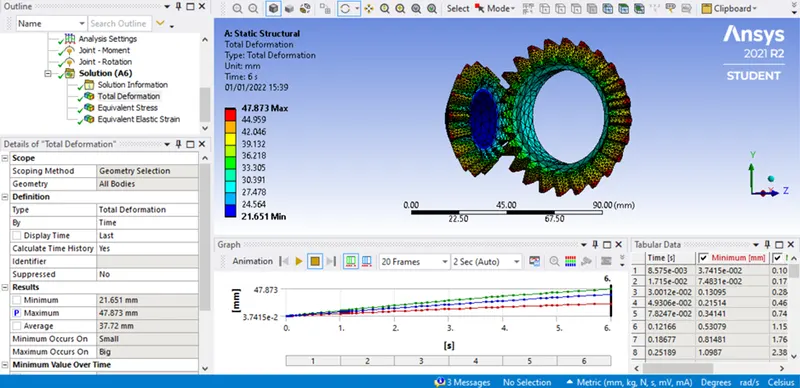
Fig. 4 Total deformation in mm
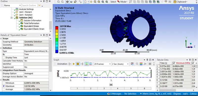
Fig. 5 Von Mises stress in MPa
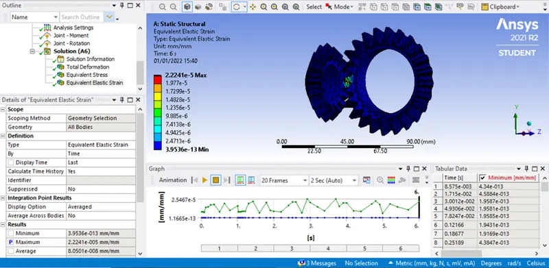
Fig. 6 Equivalent elastic strain
CASE 2 (Global mesh size: 5 mm)
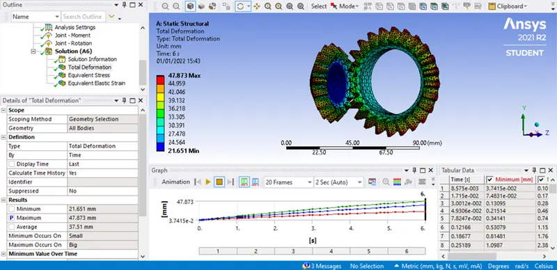
Fig. 7 Total deformation in mm
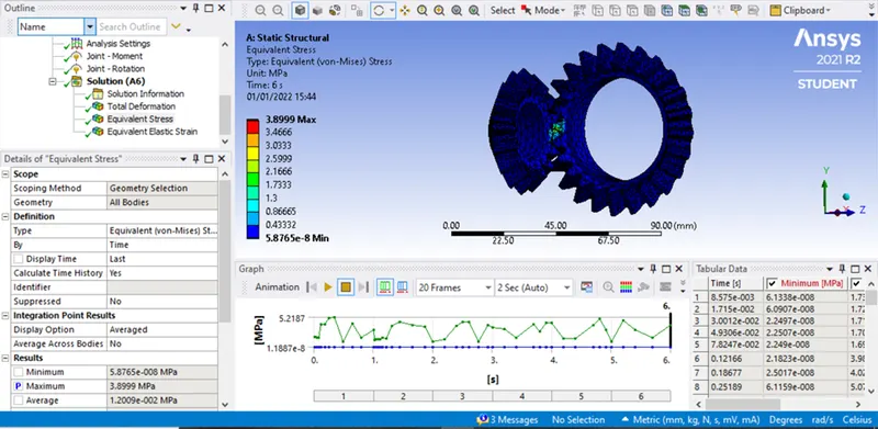
Fig. 8 Von Mises stress in MPa
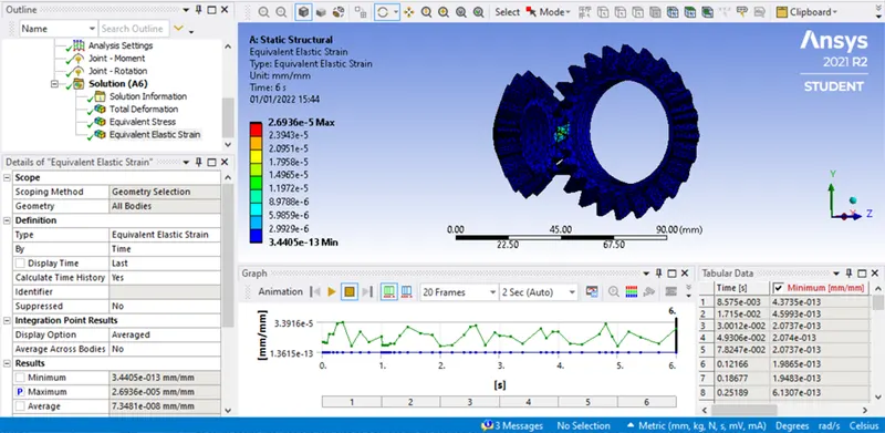
Fig. 9 Equivalent elastic strain
CASE 3 (Global mesh size: 4 mm)
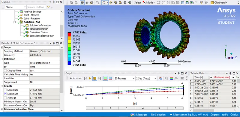
Fig. 10 Total deformation in mm
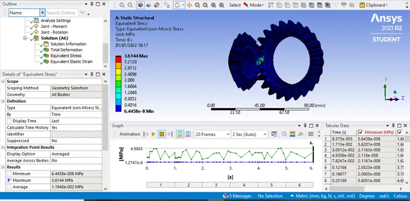
Fig. 11 Von Mises stress in MPa
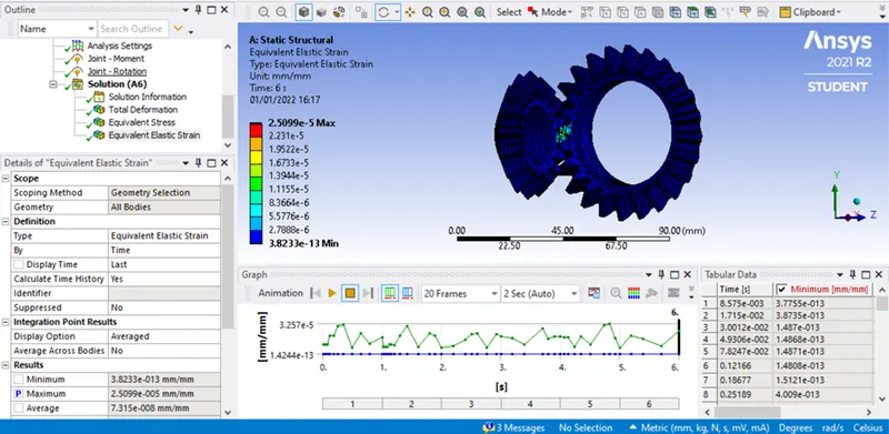
Fig. 12 Equivalent elastic strain
CONCLUSION
Numerical analysis was conducted for investigating the total deformation, von mises stress and equivalent strain by performing grid dependency test in the bevel gears made of structural steel. In all the cases of global mesh size (6mm, 5mm and 4mm), the results of von mises stress and equivalent stress changed considerably without converging to a single solution. This recommends to further refine the mesh by considering finer mesh less than 4 mm. The total deformation remained constant since the pinion gear was set to rotate for a fixed angle from 0° to 120°.