Week 2 : Basic Calibration of Single cylinder SI-Engine
Aim- The aim of this project is to evaluate ICE engine performace under different conditions.
Theory:-An internal combustion engine (ICE) is a heat engine in which the combustion of a fuel occurs with an oxidizer (usually air) in a combustion chamber that is an integral part of the working fluid flow circuit. In an internal combustion engine, the expansion of the high-temperature and high-pressure gases produced by combustion applies direct force to some component of the engine. The force is applied typically to pistons, turbine blades, a rotor, or a nozzle. This force moves the component over a distance, transforming chemical energy into useful work.
Typically a four stroke ICE consists of the following strokes
Intake stroke
- Piston moves down the cylinder bore from top dead center (TDC) to bottom dead center (BDC)
- Intake valve is open, the exhaust valve is closed
- Downward piston motion creates a vacuum (negative air pressure) that draws that air/fuel mixture into the engine via the open intake valve
Compression stroke
- Piston moves up the cylinder bore from bottom dead center to top dead center
- Both the intake and exhaust valves are closed
- Upward piston motion compresses air/fuel mixture in the combustion chamber
Power stroke
- At the end of the compression (previous) stroke, the spark plug fires and ignites the compressed air/fuel mixture. This ignition/explosion forces the piston back down the cylinder bore and rotates the crankshaft, propelling the vehicle forward.
- Piston moves down the cylinder bore from top dead center to bottom dead center
- Both the intake and exhaust valve are closed
Exhaust stroke
- Piston moves up the cylinder bore from bottom dead center to top dead center. The momentum caused by the power stroke is what continues the crankshaft movement and the other 3 strokes consecutively.
- Intake valve is closed, the exhaust valve is open
- This final stroke forces the spent gasses/exhaust out of the cylinder. The cycle in now complete and the piston is ready to begin the intake stroke.
The below diagram gives a visual representation of how this process works:
Case Setup and Results
CASE 1:- Engine at 1800 rpm
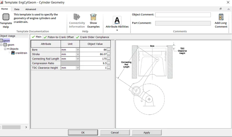
The engine geometry has the following parameters
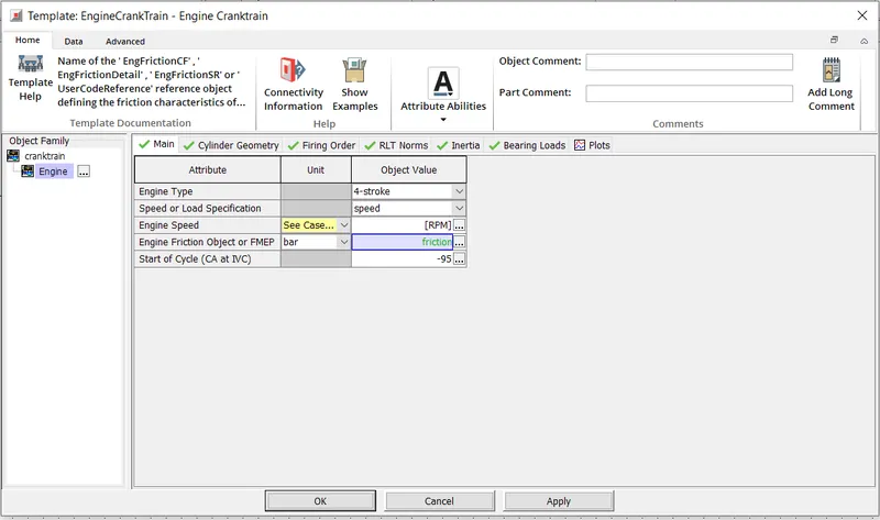
The engine revolution is set to 1800 rpm by clicking on the Engine Cranktrain object
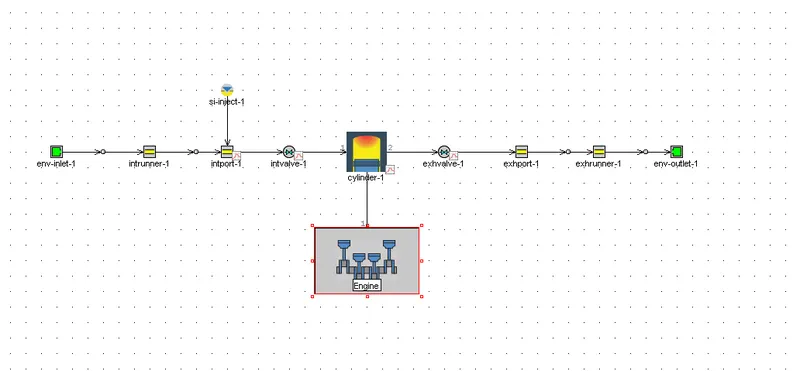
The simulation is run by keeping all other parameters to default.
The following outputs are obtained as shown below
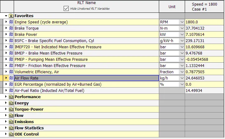
(From the below plot)
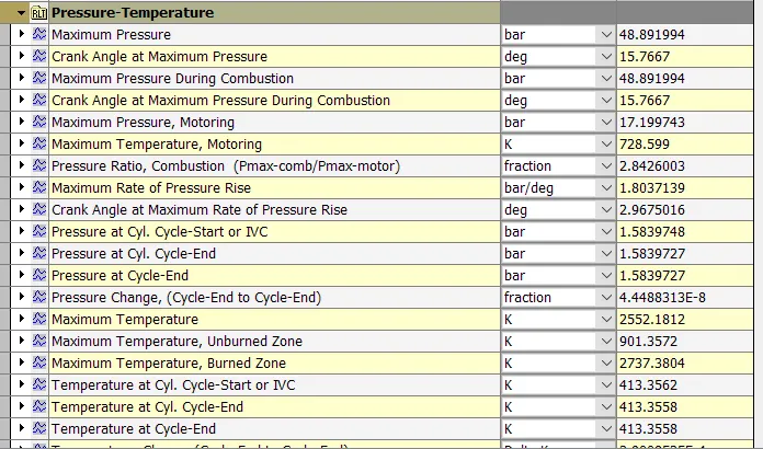
Air Flow Rate = 24.646053 kg/h
BMEP = 9.476768 bar
BSFC-= 239.17131 g/kW-h
Max Cylinder Pressure- 48.89 bar
Case II - At 3600 rpm
Retaining the same engine geometry parameters, We run the simulation at 3600rpm and obtain the following output
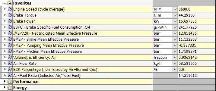
It is noted that the power output is at 3600 rpm is 16.697336 kW.
Case 3
The formula for calculating the Brake power of an engine is shown in the below plot
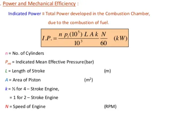
Our goal is to increase the Power output at 3600 rpm. From the above equation, we infer that Power output is dependent on engine geometry which in turn is dependent on engine geometric parameters such as Bore, stroke and connecting rod length. Also it is dependent on the mean effective pressure.
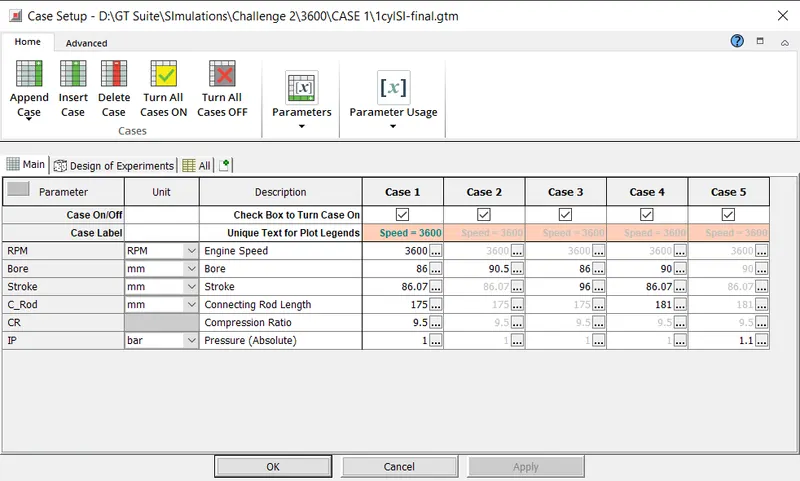
Using the Case Setup feature of GT SUITE, we add the following parameters and cases. These are briefly described below
1) Case 1:- The default case setup at 3600 rpm
2) Case 2:- Bore dimension is changed from 86mm to 90.5mm. All other parameters are the same as Case 1
3) Case 3:- Stroke length is changed from 86.07mm to 96mm. All other parameters are the same as Case 1
4) Case 4:- Bore dimension changed to 90mm and connecting rod length changed to 181mm.
5) Case 5:- Intake pressure changed from 1 bar to 1.1 bar
The snapshot of the case setup is shown below.
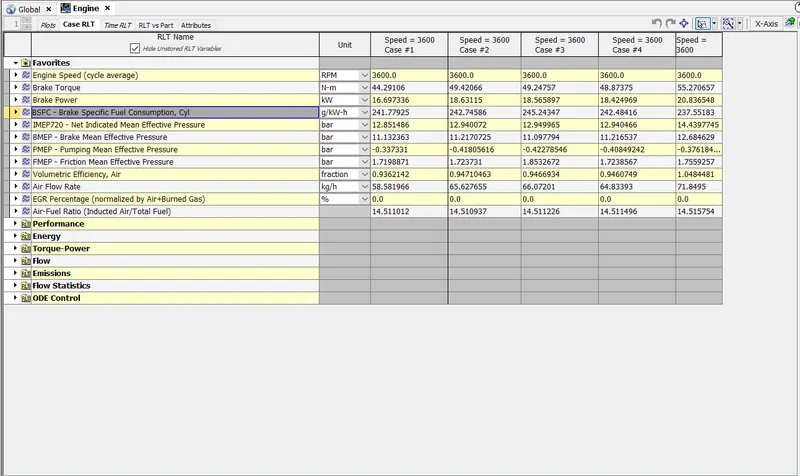
By running the simulation the following outputs are obtained
i) Case 1 - 16.697336 kW
ii) Case 2 - 18.63115 kW (Increase of 11.5 %)
iii) Case 3- 18.565897 kW (Increase of 10.06 %)
iv) Case 4- 18.424969 kw ( Increase of 9.37 %)
v) Case 5-20.836548 kW (Increase of 19.48%)
Conclusion:-
In this project, the factors on which the engine power output depends on is understood. For a given speed, varying the engine geometric parameters will result in increase in power output