Week 2 Air standard Cycle
AIM -
Writing code that can solve an otto cycle and make plots for it.
Objective -
Objective of this report is to make MATLAB CODE to solve otto cycle in which we can get the PV diagram of otto cycle . Also ,Calculate Thermal Efficiency of an engine.
Theory -
1.Otto Cycle -
In 1876, a German engineer, Nikolaus August Otto advanced the study of heat engines by building of the first working four-stroke engine. a stationary engine using a coal gas-air mixture for fuel. Wilhelm Maybach (1846-1929), one of the most important German engineers, perfected the construction, which was produced in large quantities already at the end of the year 1876. These inventions quickly reshaped the world in which they lived.
The cycle of the Otto engine is called the Otto cycle. It is the one of most common thermodynamic cycles that can be found in automobile engines and describes the functioning of a typical spark ignition piston engine. In contrast to Carnot cycle, the Otto cycle does not execute isothermal processes, because these must be performed very slowly. In an ideal Otto cycle, the system executing the cycle undergoes a series of four internally reversible processes: two isentropic (reversible adiabatic) processes alternated with two isochoric processes.
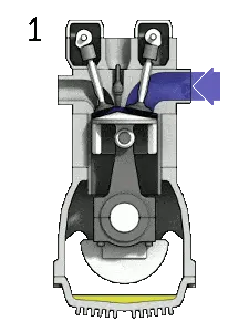
1.1.Otto cycle Process -
In an ideal Otto cycle, the system executing the cycle undergoes a series of four internally reversible processes: two isentropic (reversible adiabatic) processes alternated with two isochoric processes:
- Isentropic compression (compression stroke) – The gas (fuel-air mixture) is compressed adiabatically from state 1 to state 2, as the piston moves from bottom dead center to top dead center. The surroundings do work on the gas, increasing its internal energy (temperature) and compressing it. On the other hand the entropy remains unchanged. The changes in volumes and its the ratio (V1 / V2) is known as the compression ratio.
- Isochoric compression (ignition phase) – In this phase (between state 2 and state 3) there is a constant-volume (the piston is at rest ) heat transfer to the air from an external source while the piston is at rest at top dead center. This process is intended to represent the ignition of the fuel–air mixture injected into the chamber and the subsequent rapid burning. The pressure rises and the ratio (P3 / P2) is known as the “explosion ratio”.
- Isentropic expansion (power stroke) – The gas expands adiabatically from state 3 to state 4, as the piston moves from top dead center to bottom dead center. The gas does work on the surroundings (piston) and loses an amount of internal energy equal to the work that leaves the system. Again the entropy remains unchanged. The volume ratio (V4 / V3) is known as the isentropic expansion ration, but for Otto cycle, it is equal to the compression ratio.
- Isochoric decompression (exhaust stroke) – In this phase the cycle completes by a constant-volume process in which heat is rejected from the air while the piston is at bottom dead center. The working gas pressure drops instantaneously from point 4 to point 1. The exhaust valve opens at point 4. The exhaust stroke is directly after this decompression. As the piston moves from bottom dead center (point 1) to top dead center (point 0) with the exhaust valve opened, the gaseous mixture is vented to the atmosphere and the process starts anew.
During the Otto cycle, work is done on the gas by the piston between states 1 and 2 (isentropic compression). Work is done by the gas on the piston between stages 3 and 4 (isentropic expansion). The difference between the work done by the gas and the work done on the gas is the net work produced by the cycle and it corresponds to the area enclosed by the cycle curve. The work produced by the cycle times the rate of the cycle (cycles per second) is equal to the power produced by the Otto engine.
1.2.Thermal Efficiency of Otto Cycle -
In general the thermal efficiency ,η, of any heat engine is defined as the ratio of the work it does,W, to the heat input at the high temperature, Q.
η=WQ
The thermal efficiency ,η, represents the fraction of heat,Q, that is converted to work. Since energy is conserved according to the first law of thermodynamics and energy cannot be be converted to work completely, the heat input, QH, must equal the work done, W, plus the heat that must be dissipated as waste heat Qc
into the environment.
We can write the formula for thermal efficiency as -
η=1− (t4−t1/t3−t2)
→ηO=1−(v1/v2)γ−1=1−1/(c^γ−1*r)
where,
t1, t2, t3, t4 = Temperatures at all four state
ηO = Efficiency of Otto cycle
v1, v2 = Volumes at first two state
cr = Compression ratio
γ = Ratio of constant pressure and constant volume
Python Code -
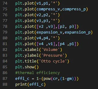
Explanation -
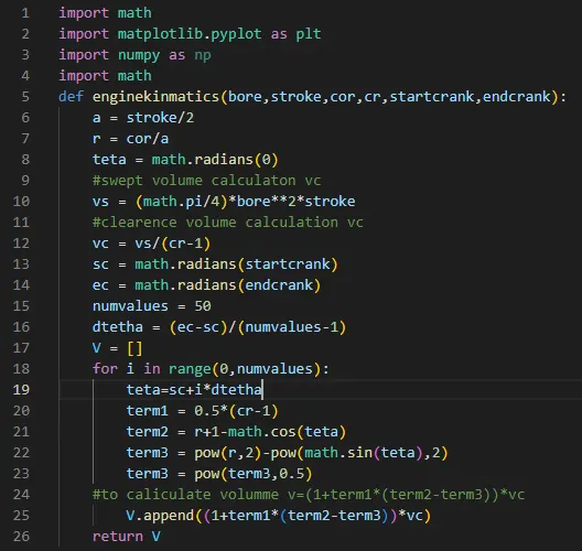
- Based on the relationship between crank angle and volume inside the chamber we make a function named engine_kinematics
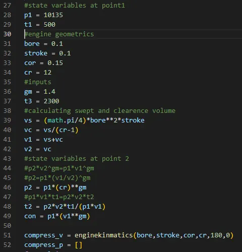
- Assign the input values.
- Calculate the swept volume, clearance volume, v1 & v2.
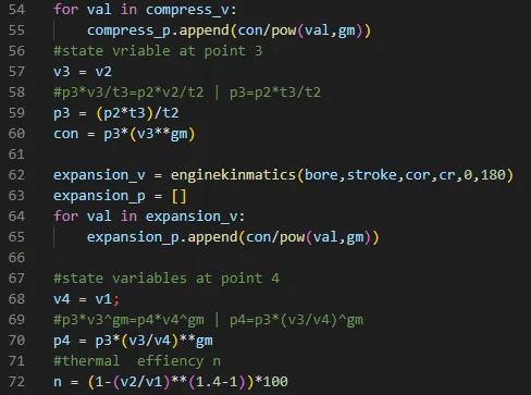
- Calculate of static variables based on the derived formulas using the given data.
- Calculate the pressure & volume during compression and expansion calling the engine_kinematics function.
- Plot of the curves which represent the thermal process based on the p & v values of four states.
- Give title and label to the graph.
- Calculation of thermal efficiency.
Output -
Plot -
Conclusion -
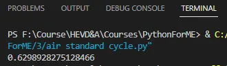
- The thermal efficiency of the otto cycle is 0.62 or 62%. Efficiency is typically less than 100% because there are inefficiencies such as friction and heatloss that convert the energy into alternative forms.
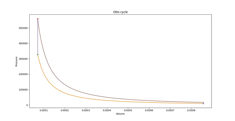
- The graph which we get is the ideal otto cycle p-v diagram. The actual otto cycle diagram is different but for the ease of calculation we generally use theideal diagram.