Week -2
Answer 1: Simulink model of Doorbell uisng Solenoid block.
Given condition is the switch should be closed for 2 seconds and then released. For this the model contains a pulse generator where it gives the output as 1 for every 2 seconds delay.
The solenoid block is used and powered using a battery block through a switch and the switch's control signal is fed from the pulse generator. Requred converters and references are used in this model. The movement of the plunger is sensed using a Ideal Translational Motion Sensor and the position output is seen using the scope.
The model for the above said description is as shown below and the same is attached as Solenoid.slx in the attachment.
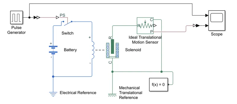
The battery volatge is kept at 12V as the solenoid block excitation voltage is 12V as well. The results obtained are as below.
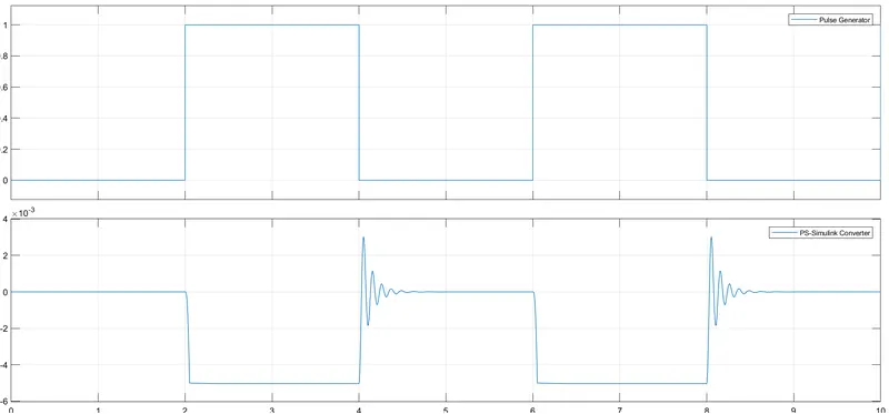
The graph above has two divisions. First division is the pulse generator output and as per the given condition the output is 1 for 2 seconds and output 0 for next 2 seconds. Second division of the graph is postion of plunger vs time. Whenever the switch is on for 2 seconds the plunger of the solenoid moves and the dispalcement can be seen in the graph. When the switch is off the plunger comes back to zero postion after sometime.
Answer 2: Using a thermistor to sense the temperature of the heater and controlling the fan.
Here the model is developed using a controlled temperature source fed by a signal builder. The controlled temperature source output i.e the temperature is sensed by the thermistor. The thermistor is placed in series with a additional resistor and connected to a battery. The voltage drop across the resistor varies as the temperature varies because as temperature varies the thermistor's resistance value changes and the voltage drop across the resistor varies. This variation is voltage drop is studied and a switch with a threshold of volatge drop at 25 deg C is configured in the Switch block.
The model below is developed based on the description above and the same is attached with the name Temp_Sense.slx
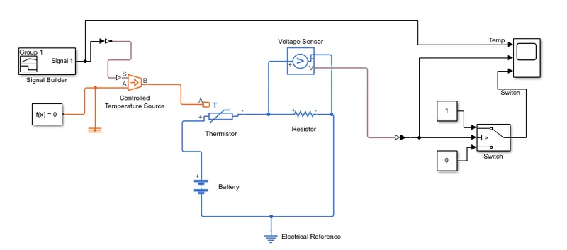
The Switch in the above model is the control input to the FAN based on given conditions.
The given conditions are ,
Temperature source: 20 °C(293.15K) from 0 to 10 seconds, 27 °C(300.15K) from 10 to 30 seconds, 23 °C(26.15K) from 30 to 50 seconds
Fan conditions: ON if the temperature above 25 °C, OFF otherwise
So, in this model the signal builder gives the temperature signal in Kelvin. According to the given conditions the Fan has to be on between 10 to 30 seconds of time duration, i.e the switch ouput should be 1 from 10 to 30 seconds of time period and the same can be seen in the graph taken from the scope which is as below,
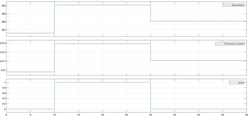
The above graph has 3 divisions. First divisoin is temperature vs time. Second division is Voltage drop vs time. Third division is Control signal/ Switch output vs time. So by seeing the graph it is can be seen that the model behaves as per given conditions, i.e the switch output is 1 in the duration of 10 to 30 seconds when the temperature is above 25 deg C.
The output of this switch can be given as input control to the Fan and it turns on when the temperature is above 25 deg C.