Week -2
1.
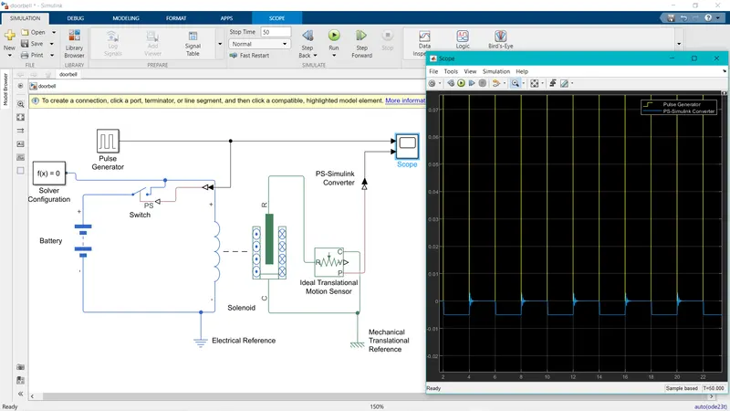
In this door bell model the main components that i have used is a solenoid block, battery, a controlled switch and a pulse generator.
Here the pulse generator is used to give the input to the switch to toggle it for on and off for 2sec.
The switch is externaly connected to the pulse generator, i have used battery supply for the power source.
The positive end of the solenoid is connected to the switch and battery and the negative end is connected to the electrical reference point with reference there is a solver configuration connected to the physical system.
In the solenoid blockset the port are is connected to the ideal translational motion sensor in order to measure the output of the plunger movement. The out signal is taken from the sensor and connected to a scope with the help of a PS-Simulink Converter. I have also connected the pulse generator signal to the scope in order to compare the output signal with respect to input.
Here in the plot we can see the pulse generated the Yellow colour pulse represents the input pulse generator signal and the blue colour pulse signal represents the output plunger movement the time is set for 2sec i.e for every 2sec the switch is closed and opened.
2.
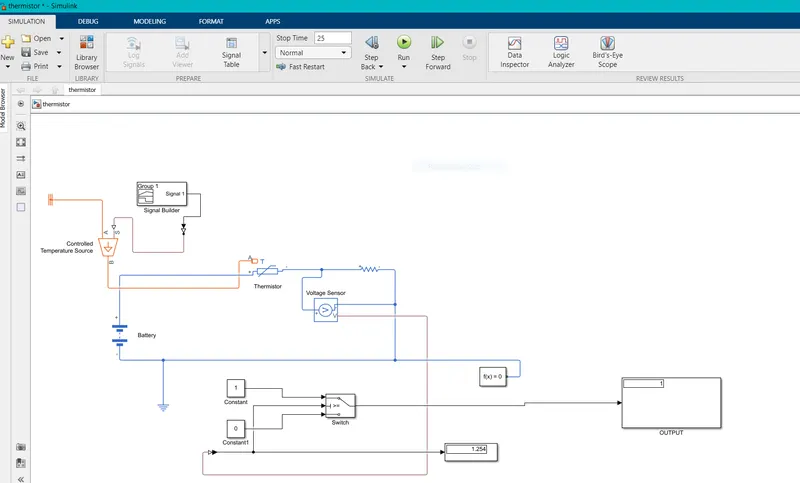
The components used in this model are
- Thermistor
- Signal builder
- controlled temperature source
- Resistor
- Voltage sensor
- Battery
- Switch
- Display
- Simulink-PS converter/ PS-simulink converter
- Solver configuration
As given in the condition (20 deg C from 0 to 10 sec, 27 deg C from 10 to 30, 23 deg C from 30to 50 sec), all these values are given as input to the signal builder block and is configured as per the condition.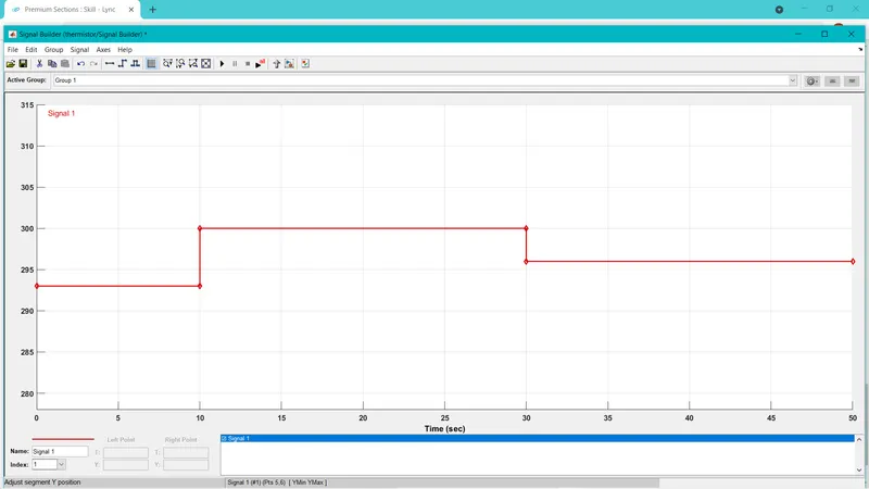
all these signals are sent to the thermistor between them we need to add a Controlled temperature source because the thermistor wiil not understand the signal from the signal builder block.
The output of the controlled temperature source is given as input to the thermister.
A voltage sensor is used across the resistor to measure the voltage as a threshould value for the condition.
To fullfill the condition of the fan i.e (ON if temperature is more than 25 deg C ,OFF otherwise)
so a threshold value is noted for temperature 25 Deg C and this threshold value is given to the Switch provided .
In the switch if the voltage value exceeds the threshold voltage the switch is turned ON i.e Logic 1 otherwise OFF Logic 0.
Here we can see in the output block the value is 1 i.e the fan is turned on because the time i have selected is between 0 to 30 the temperature is above 25 deg C
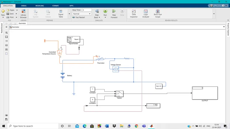
And here we can see the fan OFF condition because the time taken between 0 to 10 i.e the temperature is below 25 deg C