Week -2
1.Make a simulink model of doorbell using solenoid by using simulink
when the switch is closed the electromagnet receives electrical power from the battery and pulls the metal arm to hit the bell producing sound.
In simulink model the basic blocks that are used are solenoid, battery, pulse generator, simulink to pv system, switch, battery, ideal translational source.
solenoid is an inductance whose value depends on the plunger position.soleniod s arre usually found in the applications where automatically turn the application ON or OFF is required.
pulse generator is used as input signal, simulink to pv system is used to convert input signal to physical system, Ideal translational sensor block is used to sense the position of the plunger.
solver configuration is used to specify the solver parameters that model needs before the simulation.
pulse generator is connected to one side of switch through simulink to pv system, battery and solenoid is also connected to another side of the switch, one side of solenoid is connected to ideal translational motion sensor and is connected to scope through pv system to simulink.
intially there was a delay of 2 seconds in the system and the value is zero from zero to 2 seconds later the valu of plunger varies with interval of 2 seconds.
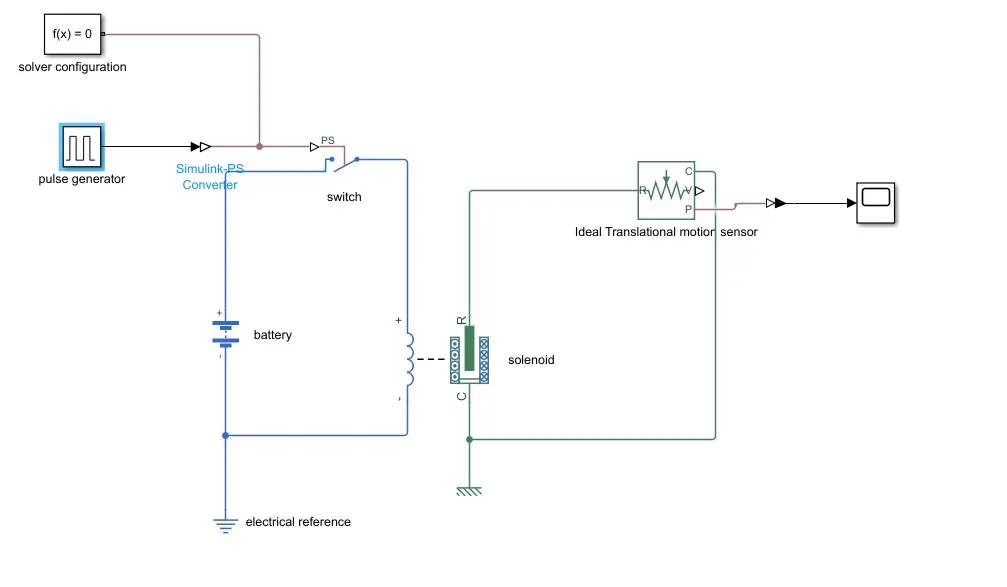
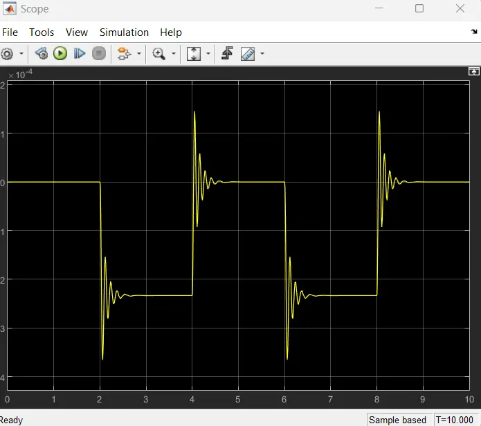
the above are the simulink model of the doorbell and its scope.
2. Use a thermistor to sense the temperature of a heater and turn on or turn off the fan according to the conditions
Fan is ON if the temperature is above 25 degree C otherwise turn OFF
the basic blocks that are used in this simulink model are thermistor, controlled temperature source, resistor, voltage sensor block, switch, signal editor
The controlled temperature source represents an ideal source of thermal energywhich maintain specified temperature difference scross the source
The signal editor is used to set the signal according to our requirement. voltage sensor block is used to sense the voltage
In this model signal editor block is connected to controlled temperature sensor through simulink to ps system, the other end of controlled temperature is connected to thermistor, thermistor is connected to resistor and voltage sensor is connected across the resistor, switch is connected to voltage block
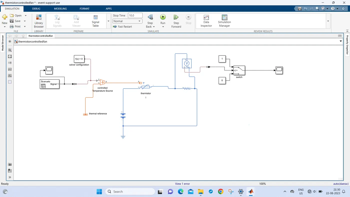

the above are the simulink model for the thermistor controlled fan, The fan is ON when the temperature is above 25 degree C otherwise it is turned OFF.