Week -2
SIMULINK Week -2 assignment
ABSTARCT
The report delineates about building the conventional Doorbell using solenoid block which is instrumental in the functioning of Doorbell in Simulink. Additionally, creating a scenario where the switch closes for every 2 seconds and study the mechanical movement of plunger. Furthermore, another Simulink model is built by using Thermistor Simulink-block to sense the temperature based on that fan is started to cool the system. The step-by-step Simulink blocks set up to generate the results by simulating the Simulink model.
THEORY
The following paragraphs gives a brief theory on Doorbell using solenoid, usage of thermistor for controlling the temperature and Simulink blocks used in the simulation.
DOORBELL USING SOLENOID
It is a mechanical or electronic bell that functions by means of an electromagnet. When an electric current is applied, it produces a repetitive buzzing, clanging or ringing sound.
The most important part of a Doorbell is its magnetic motor. The magnetic motor contains a conventional electromagnet. As it is well known fact that Electromagnets work on a rudimentary principle. An electromagnet is a setting in which a coil of wire is wrapped around magnetic material which yield magnetic field when electricity is passed through the coil. The larger the coiling of the wire, the higher the amplification of magnetic field. This magnetic field produces a substantial effect on any magnetic substance when brought in the vicinity of its magnetic field. This means that when an iron object is placed in this magnetic field, it will be attracted towards the magnetic field due to polar orientation generated by the electromagnetism.
As there would be magnetic field around a permanent magnet, the magnetic field of an electromagnet has a polar orientation a "north" end and a "south" end then it is attracted to iron objects. When you hold down a doorbell button, it closes an electrical circuit so that household current flows through the electromagnet through a transformer. The transformer is a simple device that takes the 120-volt household current and steps it down to a 10-volt current (see Inside a Power-Cube Transformer to find out how). This current is then passed through the electromagnet wire. The magnetic field of the electromagnet is put to work to drive some sort of a noisemaking apparatus. There are a plenty of different ways to configure the doorbell components in order to produce different sorts of noises.
The below is the picture depicts Doorbell configuration:
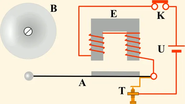
B-Door bell
E-Electromagnet
K-Switch
U-Battery
T- Spring
A- Soft Iron Armature
THERMISTOR: A thermistor is a thermally sensitive resistor that exhibits a precise and predictable change in resistance proportional to small changes in body temperature. How much its resistance will change is dependent upon its unique composition. Thermistors are part of a larger group of passive components and unlike their active component counterparts, passive devices are incapable of providing power gain, or amplification to a circuit.
There are two types of thermistors: NTC or Negative Temperature Coefficient thermistors, and PTC or Positive Temperature Coefficient thermistors. The difference is that NTC thermistors exhibit a DECREASE in resistance as body temperature increases, while PTC thermistors exhibit an INCREASE in resistance as body temperature increases.
Applications for NTC and PTC Thermistors include: Temperature Compensation, Temperature Measurement, Temperature Control and Inrush Current Limiting.
NTC Thermistors are non-linear, and as their name suggests, their resistance decreases as temperature increases. A phenomenon called self-heating may affect the resistance of an NTC thermistor. When current flows through the NTC thermistor, it absorbs the heat causing its own temperature to rise.
Positive Temperature Coefficient thermistors (PTC) offer a passive approach to limiting inrush current. By implementing a PTC thermistor, you’ll likely see a reduction in operating costs with higher reliability; without compromising protection. PTC thermistors experience a change in resistance if there is a change in the ambient temperature or the device self-heats because it absorbs incoming current. And, since limiting inrush current relies on the specified resistance of a PTC thermistor, making the right selection plays a crucial role in system protection.
Benefits of NTC and PTC Thermistors
NTC Thermistors are rugged, reliable, and stable, and they are equipped to handle extreme environmental conditions and noise immunity more so than other types of temperature sensors.
Compact size: Packaging options allow them to operate in small or tight spaces; thereby taking up less real estate on printed circuit boards.
Fast response time: The small dimensions allow for a quick response to change in temperature, which is important when immediate feedback is required.
Cost efficient: Not only are thermistors less expensive than other types of temperature sensors; if the purchased thermistor has the correct RT curve, no other calibration is necessary during installation or over its operational life.
Point match: The ability to obtain a specific resistance at a particular temperature.
Curve match: Interchangeable thermistors with the accuracy of +0.1˚C to + 0.2˚C.
SIMULINK BLOCKS USED
The following are the Simulink blocks used in the development of the Simulink-Doorbell model and Temperature control of fan is using Thermistor:
1. Pulse Generator: it generates square wave pulses at regular intervals. he Pulse Generator block generates square wave pulses at regular intervals. The parameters that define waveform are Amplitude, Pulse width, Period, Phase delay. The below diagram depicts how the parameters shape the waveform:
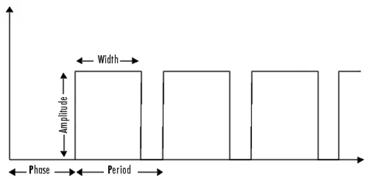
The below is the pulse generator diagram:
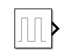
The block's Pulse type parameter allows you to specify whether the block's output is time-based, or sample based. If you select sample-based, the block computes its outputs at fixed intervals that you specify. If you select time-based, Simulink computes the block's outputs only at times when the output actually changes. This can result in fewer computations being required to compute the block's output over the simulation time period.
The pulse generator offers two modes: time-based and sample based. An important difference between the time-based and sample-based modes is that in time-based mode, the block output is based on simulation time, and in sample-based mode, the block output depends only on the simulation start, regardless of elapsed simulation time.
2. Scope: the basic function of scope is to display signals generated during a simulation. The Scope block displays its input with respect to simulation time. The Scope block can have multiple axes and all axes have a common time range with independenty-axes. The Scope allows you to adjust the amount of time and the range of input values displayed. The scope parameters can be modified during the simulation.
When you start a simulation, Simulink does not open Scope windows, although it does write data to connected Scopes. As a result, if you open a Scope after a simulation, the Scope's input signal or signals will be displayed.
If the signal is continuous, the Scope produces a point-to-point plot. If the signal is discrete, the Scope produces a stair-step plot.
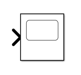
The Scope provides toolbar buttons that enable you to zoom in on displayed data, display all the data input to the Scope, preserve axis settings from one simulation to the next, limit data displayed, and save data to the workspace. The below is the picture depicting the Scope:
3. Simulink-PS Convertor: it basically converts input signal into physical signal. The Simulink-PS Converter block converts the input Simulink signal into a physical signal. Use this block to connect Simulink sources or other Simulink blocks to the inputs of a Physical Network diagram. The below is the diagram:
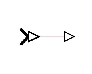
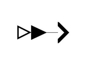
4. PS-Simulink Converter: it Converts physical signal into Simulink output signal. The PS-Simulink Converter block converts a physical signal into a Simulink output signal. Use this block to connect outputs of a Physical Network diagram to Simulink scopes or other Simulink blocks. The below is the diagram:
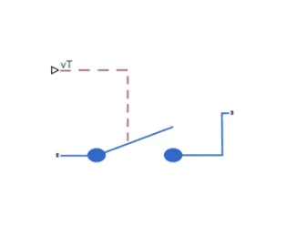
5. SPST SWITCH: it is Single pole single throw switch and a basic ON/OFF switch, that is utilized to connect or break the connection between two terminals. The power supply for the owl circuit is given by this switch. A simple PST switch is shown below. The application of SPST switch is light switch given below and it is also called as a toggle switch. This block supports both reflective and absorptive switches. The control signal is a Simulink®signal connected to the Vctl port of the block. The control signal specifies when the output port, Out, transmits the input signal at the input port, In. The below picture of the SPST switch:
When the switch is open, port p is connected to port n through a resistance with value equal to the reciprocal of the Open conductance parameter value otherwise, otherwise the switch is closed, port p is connected to port n through a resistance with value equal to the Closed resistance parameter value.
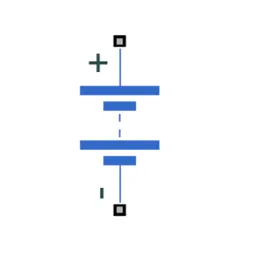
6. Battery: it is the power source to operate electrical equipment. If you select Infinite for the Battery charge capacity parameter, the block models the battery as a series internal resistance and a constant voltage source. If you select Finite for the Battery charge capacity parameter, the block models the battery as a series internal resistance plus a charge-dependent voltage source defined by:
V = Vnom*SOC/(1-beta*(1-SOC))
where SOC is the state of charge and Vnom is the nominal voltage. Coefficient beta is calculated to satisfy a user-defined data point [AH1,V1]. The below is the symbol of battery:
7. Electrical Reference: it nothing but connection to the ground. The electrical conserving ports of all the blocks that are directly connected to ground must be connected to an Electrical Reference block. A model with electrical elements must contain at least one Electrical Reference block. The below is picture depicts the Electrical Reference:
8. Solenoid: this block represents the electrical characteristics and generated force for the solenoid. Solenoid is the generic term for a coil of wire used as an electromagnet. It also refers to any device that converts electrical energy to mechanical energy using a solenoid. The device creates a magnetic field from electric current and uses the magnetic field to create linear motion. when electrically energized or de-energized, either shut off or allow fluid flow. The actuator takes the form of an electromagnet. When energized, a magnetic field builds up which pulls a plunger or pivoted armature against the action of a spring. When de-energized, the plunger or pivoted armature is returned to its original position by the spring action. The below is picture of solenoid:
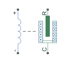
C- Mechanical translational conserving port associated with the case.
R- Mechanical translational conserving port associated with the plunger.
9. The Ideal Translational Motion Sensor: this block represents a device that converts an across variable measured between two mechanical translational nodes into a control signal proportional to velocity or position. You can specify the initial position (offset) as a block parameter. The sensor is ideal since it does not account for inertia, friction, delays, energy consumption, and so on.
Connections R and C are mechanical translational conserving ports that connect the block to the nodes whose motion is being monitored. Connections V and P is physical signal output ports for velocity and position, respectively.
The block positive direction is from port R to port C. This means that the velocity is measured as v = vR – vC, where vR, vC are the absolute velocities at ports R and C, respectively. The below is diagram of The Ideal Translational Motion Sensor:
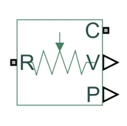
R- Rod (Positive Probe) Mechanical translational conserving port associated with the sensor positive probe.
V-Velocity in m/s, Physical signal output port for velocity.
C-Case reference probe. Mechanical translational conserving port associated with the sensor negative (reference) probe.
P-position in m, Physical signal output port for position.
10. Solver Configuration: this block specifies the global environment information and provides parameters for the solver that your model needs before you can begin simulation.
The below is picture depicts the Slover configuration:
A solver applies a numerical method to solve the set of ordinary differential equations that represent the model. Through this computation, it determines the time of the next simulation step. Each topologically distinct Simscape block diagram requires exactly one Solver Configuration block to be connected to it. The block has one conserving port. You can add this block anywhere on a physical network circuit by creating a branching point and connecting it to the only port of the Solver Configuration block.
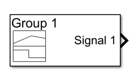
11. Signal Builder: it creates and generates interchangeable groups of signals whose waveforms are piecewise linear signal sources and use them in a model. One can quickly switch the signal groups into and out of a model to facilitate testing. In the Signal Builder window, create signals and define the output waveforms. The below is the symbol the Signal builder block:
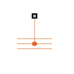
12. Thermal Reference: this block represents a thermal reference point, that is, a point with an absolute zero temperature, with respect to which all the temperatures in the system are determined.
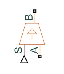
13. Controlled Temperature Source: this block represents an ideal source of thermal energy that is powerful enough to maintain specified temperature difference across the source regardless of the heat flow consumed by the system.
Connections A and B are thermal conserving ports corresponding to the source inlet and outlet, respectively. Port S is a physical signal port, through which the control signal that drives the source is applied. You can use the entire variety of Simulink signal sources to generate the desired heat flow variation profile. The temperature differential across the source is directly proportional to the signal at the control port S.
The block positive direction is from port A to port B. This means that the temperature differential is determined as TB – TA, where TB and TA are the temperatures at source ports. The below is the picture depicts:
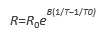
14. Thermistor: The Thermistor block represents an NTC thermistor using the B-parameter equation. The resistance at temperature T is
where:
R0 is the nominal resistance at the reference temperature T0.
B is the characteristic temperature constant.
The following equation describes the thermal behavior of the block:
where:
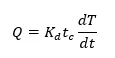
Q is the net heat flow into port A.
Kd is the Dissipation factor parameter value.
tc is the Thermal time constant parameter value.
dT/dt is the rate of change of the temperature.
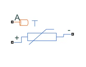
The below is the Thermistor picture:
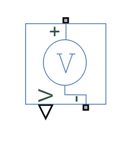
15. Voltage Sensor: this block represents an ideal voltage sensor, that is, a device that converts voltage measured between two points of an electrical circuit into a physical signal proportional to the voltage.
The connections + and – are electrical conserving ports through which the sensor is connected to the circuit. Connection V is a physical signal port that outputs the measurement result.
+ : Electrical conserving port associated with the sensor positive terminal.
- : Electrical conserving port associated with the sensor negative terminal.
V: Physical signal output port for voltage.
The below is picture represents:
16. Display: this block connects to a signal in model and displays its value during simulation. The appearance and format of the Display block can be configured to make intuitive sense for the value it displays. The Parameters of the Display block can be edited during simulation. The Display block can display complex, vector, and 2-D matrix signals. Use the Display block with other dashboard blocks to build an interactive dashboard of controls and indicators for your model. The below is the picture of Display Block:

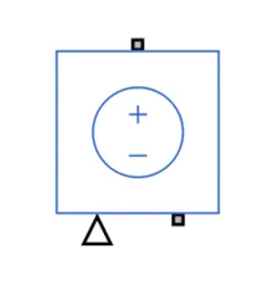
17. Controlled Voltage Source :The block represents an ideal voltage source that is powerful enough to maintain the specified voltage at its output regardless of the current passing through it. The output voltage is V = Vs, where Vs is the numerical value presented at the physical signal port. The below is the diagram that depicts Controlled Voltage Source:
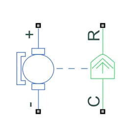
18. DC Motor: Converts input electrical energy into mechanical motion. The below is the picture of the DC motor. This block represents the electrical and torque characteristics of a DC motor. The block assumes that no electromagnetic energy is lost, and hence the back-emf and torque constants have the same numerical value when in SI units. Motor parameters can either be specified directly or derived from no-load speed and stall torque. If no information is available on armature inductance, this parameter can be set to some small non-zero value.
When a positive current flow from the electrical + to - ports, a positive torque acts from the mechanical C to R ports. Motor torque direction can be changed by altering the sign of the back-emf or torque constants. The below is the DC motors diagram:
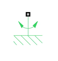
19. Mechanical Rotational Reference: this block represents a reference point, or frame, for all mechanical rotational ports. All rotational ports that are rigidly clamped to the frame (ground) must be connected to a Mechanical Rotational Reference block. The below is diagram that represents:
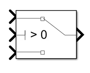
20. Switch: this block passes through the first input or the third input signal based on the value of the second input. The first and third inputs are data input. The second input is a control input. Specify the condition under which the block passes the first input by using the Criteria for passing first input and Threshold parameters. The symbol of the Switch is below shown:
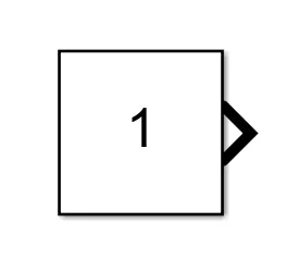
21. Constant: The Constant block generates a real or complex constant value signal. Use this block to provide a constant signal input. The block generates scalar, vector, or matrix output, depending on: The dimensionality of the Constant value parameter and the setting of the Interpret vector parameters as 1-D parameter. The below is symbol of the constant block:
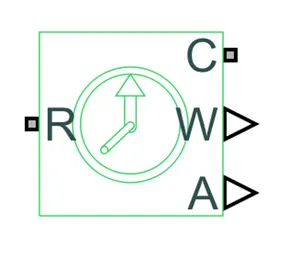
22. Ideal Rotational Motion Sensor: this block represents an ideal mechanical rotational motion sensor, that is, a device that converts an across variable measured between two mechanical rotational nodes into a control signal proportional to angular velocity or angle. You can specify the initial angular position (offset) as a block parameter.
The sensor is ideal since it does not account for inertia, friction, delays, energy consumption, and so on.
Connections R and C are mechanical rotational conserving ports that connect the block to the nodes whose motion is being monitored. Connections W and A are physical signal output ports for velocity and angular displacement, respectively.
The block positive direction is from port R to port C. This means that the velocity is measured as ω = ωR – ωC, where ωR, ωC are the absolute angular velocities at ports R and C, respectively.
STEP-BY-STEP DESCRIPTION OF SIMULINK BLOCKS USAGE:
DOORBELL USING SOLENOID
The following paragraphs illustrate about the step by step set up of the blocks in Simulink to develop a doorbell using solenoid and resulting to observe the physical movement of the plunger. Initially, entire Simulink model set up for the Doorbell using Solenoid is shown below:
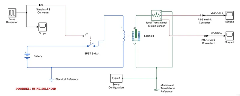
For this simulation, the following Simulink blocks are used namely : Pulse Generator, Scope, Simulink-PS convertor, SPST Switch, Battery, Electrical Reference, Mechanical Translational Reference, Solenoid, Ideal Translational Motion Sensor, PS-Simulink Convertor. The following are steps involved in building Simulink Model:
1. To start with, I need to provide signal to the system to for that I utilized the Pulse Generator block. The Pulse Generator block is brought from Simulink Browser Library. The below is the block dialogue box with input parameters:
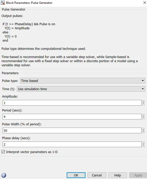
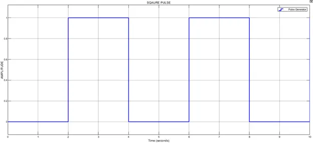
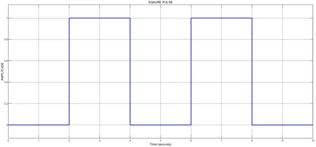
Basically, it’s time based pulse type, Time is based on the simulation time, Amplitude is 1, time period is 4 seconds, Pulse width provided is 50% of the time period and based on input, I have to delay the bell ring by 2 seconds that is provided in the Phase delay. So, from the Pulse Generator, I get a pulse of amplitude 1 and for duration of 2 seconds. This signal is converted into physical signal by using Simulink-PS convertor. I have connected Pulse generator to the Simulink-PS convertor and simultaneously I connected Pulse Generator to the Scope block to visualize pulse which I am inputting. By double clicking the scope block I could see my pulse, the below diagram represents:
2. Now, in order to provide power supply to the solenoid(which is essential for the doorbell configuration), I inducted the Battery from Simulink Browser Library. The below are the battery block default parameters:
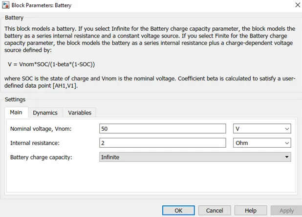
The battery given an output of 50 volts and has internal resistance of 2 ohms. Before its being connected to Solenoid, I incorporated switch. The battery -ve terminal is connected to the Electrical reference for grounding.
3. The SPST switch is Single Pole Single Throw switch is controlled by external signal vT. This switch plays important role, if the external voltage is greater than the Threshold voltage then current or voltage pass through solenoid. The below are the input parameters for the SPST switch:
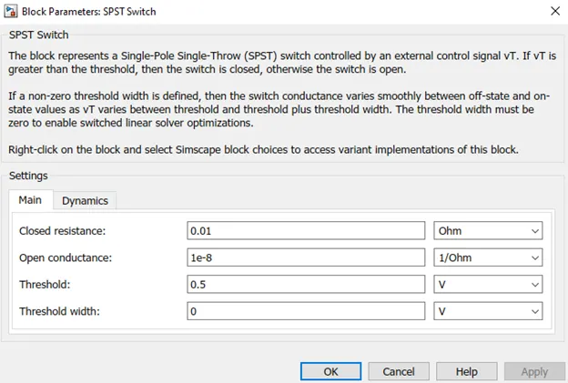
From the picture, it is observed that Threshold voltage is 0.5 Volts and Voltage provided by battery is 50 volts, so, the current pass through the switch to solenoid. The Battery +ve is connected to input port of switch, the converted physical signal coming from ‘Simulink-PS Convertor is connected to ‘vT’ terminal of switch.
4. The Solenoid is inducted into Simulink modelling space from Simulink Browser Library. The output terminal of SPST switch is connected to the Solenoid’s +ve terminal and Solenoids negative terminal is connected to Battery’s -Ve terminal. The below diagram shows the default input parameters for the Solenoid’s Magnetic force:
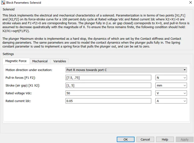
From the above diagram, the motion direction under excitation and travels from the port R to Port C, the force and stroke values are provided. The below are the Mechanical properties of solenoid:
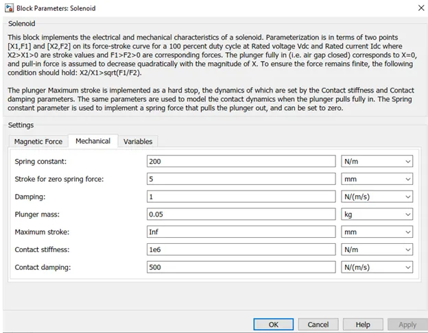
Based on the Spring constant, Stroke for zero spring force, damping, plunger mass, Maximum stroke, contact stiffness and Contact damping values, the Plunger velocity and Plunger displacement changes.
5. The Solenoid block consist of R and C ports that R for plunger and C for fixed point respectively. In order to get that Translational signals from the Solenoid, R-port has to be connected to the Ideal Translational Motion Sensor. C port of the Solenoid is connected to the Mechanical Translational Reference for rigidizing, similarly, -ve port of Solenoid is connected to Electrical reference to ground the electrical device.
6. The Ideal Translational Motion Sensor has R, C, V and P ports. The P- Port is for giving the position of the Plunger and it is connected to PS-Simulink convertor for change of Signal to Simulink signal to viewing in the results and finally connected to Scope block to plot the displacement with respect to the time. Simultaneously, The V-Port for outputting the velocity of the Plunger and it is connected to PS-Simulink convertor for change of Signal to Simulink signal to viewing in the results and finally connected to Scope block to plot the velocity with respect to the time.
7. Finally, to solve the entire Doorbell using Solenoid, the Simulink must be notified through the solver, for that, the Solver Configuration is inducted form Simulink Library Browser. The below is diagram that depicts Solver Configuration setup:
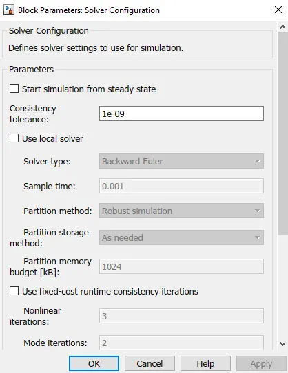
By adding this block to model setup, solver settings are defined for simulations to run. The simulation is solved. The Plots are visualized through the Scope Block.
THERMITSOR CONTROLLED FAN(DRIVEN BY DC MOTOR)
The following paragraphs illustrate about the step by step set up of the blocks in Simulink to develop a thermistor-controlled fan and observing the results of velocity and angular displacement of the fan related to DC motor operates when temperature rise above the threshold. The below is entire model setup:
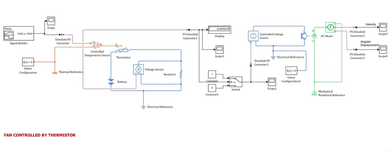
The above model setup consists of the following blocks for entire simulation to run: Pulse Generator, Scope, Simulink-PS convertor, SPST Switch, Battery, Electrical Reference, Mechanical Translational Reference, Solenoid, Ideal Translational Motion Sensor, PS-Simulink Convertor, Signal Builder, Thermal Reference, Controlled Temperature Source, Thermistor, Voltage Sensor, Display, Switch, Controlled Voltage Source, DC Motor, Mechanical Rotational Reference. The following are the steps involved in building Thermistor controlled fan:
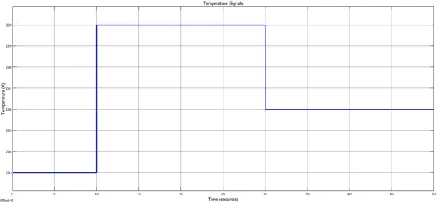
1. To start with, different temperature ranges are to be input so that the thermistor sense and based on temperatures the switch will operate to ON/OFF the fan. The different temperatures are generated through the Signal Builder Block. This block inducted into Simulink space from Simulink Library Browser. The following is the data of Temperature in Kelvin with respect to time.
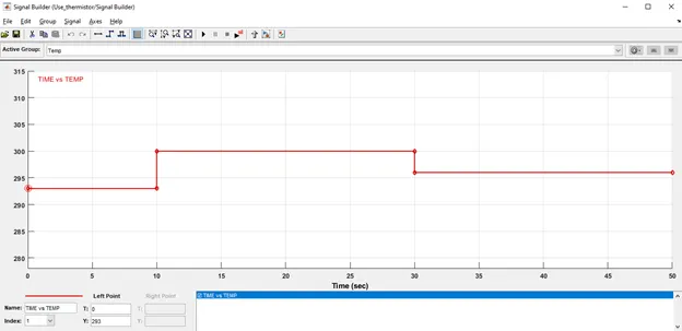
The above signal is built based on given input in degree Celsius. Temperature is 20(293K) degree Celsius for 0 to 10 seconds, 27(298K) degree Celsius for 10 to 30 seconds and 23(296K) degree Celsius for 30 to 50 seconds. The Fan should be ON for temperature above 25(298K)degree Celsius.
2. The Signal Builder is connected to Scope Block for viewing the signal. The below is signal shown in the diagram:
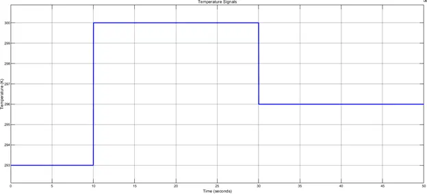
Then, in order to convert the Simulink signal to physical signal, I used to Simulink-PS Convertor. Further, it is connected to Controlled Temperature Source Block. This block is an ideal energy source in a thermal network that can maintain a controlled temperature difference regardless of the heat flow rate. The temperature difference is set by the physical signal port S. A positive temperature difference causes the temperature at port B to be greater than the temperature at port A. The port A is connected to Thermal Reference.
3. From the output of Controlled Temperature Source Block, that is port B is connected to Thermistor. Here, I am using NTC thermistor, whose resistance decreases as temperature increases. A phenomenon called self-heating may affect the resistance of an NTC thermistor. When current flows through the NTC thermistor, it absorbs the heat causing its own temperature to rise. The thermistor’s +ve terminal is connected to the battery +ve terminal as power supply must be provided. Now as the temperature changes the resistance of the Thermistor changes, but the total voltage drop remains same and equal to Battery voltage and hence the voltage drop across the resistor also changes. The voltage drop is measured with help of Voltage Sensor and PS-Simulink Convertor is connected to convert the Physical signal into Simulink signal. The Display block and Scope block are used to visualize the voltage drop across resistance and see the plot through the Scope.
4. Based on the Voltage obtained from the plot for Voltage with respective to time and correlating Temperature Vs time, the threshold voltage is determined and provided to the Switch. The Switch is triggered when temperature is greater than 25 degree Celsius. When the Switch triggers, it sends constant value 1 signal to Simulink-PS convertor to the Controlled Voltage Source. The same signal is sent to Scope to Visualize the plot.
5. Now the signal coming from Simulink-PS Convertor is sent to Controlled Voltage Source which is used to power the DC motor. Here, the dc motor considered to fan as it is rotational device. The +ve port of the Controlled Voltage Source is connected to the +ve port of DC Motor. The -ve of DC Motor port and -ve of the Controlled Voltage Source is connected to the Electrical Reference for earthing the charge.
6. When a positive current flow from the electrical + to - ports, a positive torque acts from the mechanical C to R ports. Motor torque direction can be changed by altering the sign of the back-emf or torque constants. R and C are both mechanical rotational conserving ports, and this naming convention is found throughout Simscape Electrical. The letter ‘R’ represent 'rotor' and C represents 'case'. Generally, the case is connected to a Mechanical Rotational Reference, rotor port-R is connected to Ideal Rotational Motions Sensor for knowing the velocity and angular displacement.
7. From Ideal Rotational Motions Sensor, Connections W and A are physical signal output ports for velocity and angular displacement, respectively. Now, these are converted into Simulink Signal by using PS-Simulink Convertor and then connected to Scope to see the Velocity and Angular Displacement with respect to Time. The C port is connected to Mechanical Rotational Reference. All rotational ports that are to be rigidly clamped to the frame (ground) must be connected to a Mechanical Rotational Reference block.
8. Finally, to solve the entire Model, the Simulink must be notified through the solver, for that, the Solver Configuration is inducted form Simulink Library Browser.
By adding this block to model setup, solver settings are defined for simulations to run. The simulation is solved. The Plots are visualized through the Scope Block. The simulation is made to run for 50 seconds.
OUTPUT
The following are the results obtained after running the simulation for DOORBELL USING SOLENOID and THERMITSOR CONTROLLED FAN(DRIVEN BY DC MOTOR). (DRIVEN by DC MOTOR).
DOORBELL USING SOLENOID
Based on the input provided for Pulse generator, the Period value is 4 and Pulse Width is 50 and Phase Delay is 2 and Amplitude by default is 1. From the inputs, analyzed as, initially the pulse will be 0 and there is phase delay for 2 seconds, so the pulse will start from 0 to 2 and take amplitude to 1 and gives a delay of 2 seconds and drops and these repeats for 10 seconds. The following is the output at the Scope:
Once the simulation is run, the following output is achieved through the Ideal Translational Motion Sensor and it is visualized via Scope. The below is the plot showing plunger position with respect to the time.
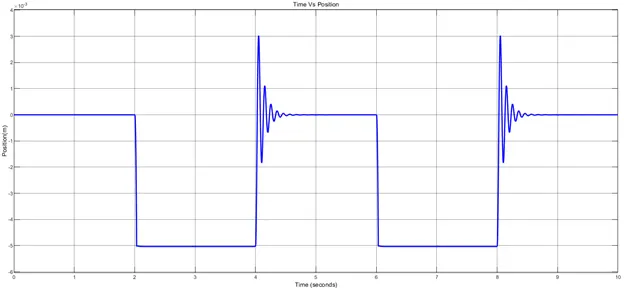
From the plot, initially Plunger is at its nominal position for phase delay of 2 seconds and when the pulse is generated the plunger moves by 5 mm that is shown in the plot and as there is 2 seconds delay the plunger goes to its nominal position and there is slight distortion due to electromagnetic interference. This cycle is repeated for 10 seconds of simulation time. During this the Plunger knocks bell to ring.
When the pulse becomes zero the plunger returns to its initial position and if the pulse goes up and down the plunger position also changes. In the plot, it is observed that during the plunger travel from its highest position to nominal position, there is distortion in the plot, this is due to recoil of the spring. This chattering observation can be reduced by decreasing the spring constant value and increasing the damping coefficient. The below figure represents the update values for the Solenoid block.
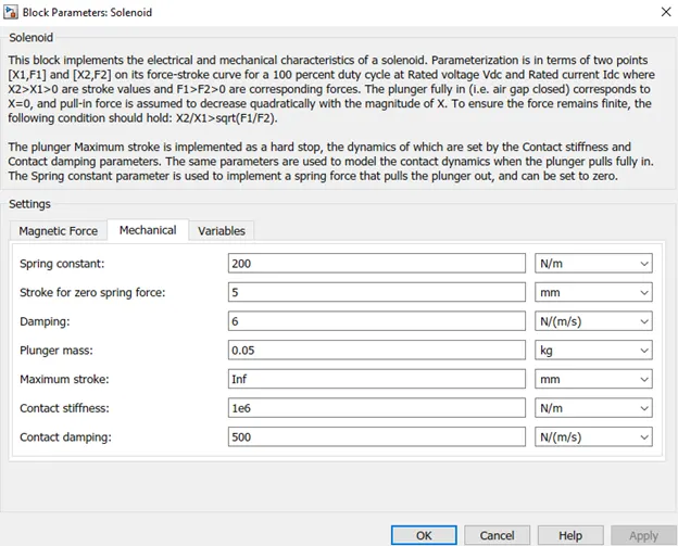
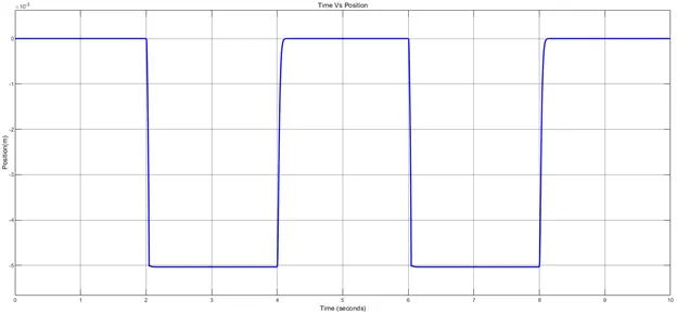
After updating Solenoid damping coefficient to 6, Final output is observed from the below plot where there no chattering in the plunger position movement.
Additionally, the Velocity plots of the plunger with respective to time is plotted, the following plot represents that:
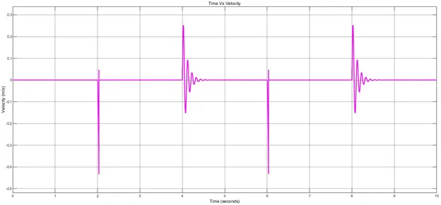
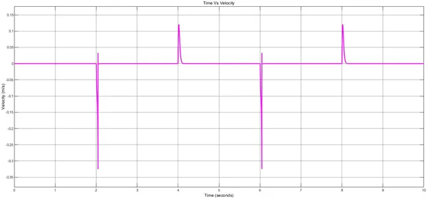
Based on updated damping coefficient, even the recoiling of the spring is not observed in the velocity plot. The Velocity plot for plunger seen below figure:
THERMITSOR CONTROLLED FAN(DRIVEN BY DC MOTOR)
The following are results generated after running Simulink model for Thermistor controlled fan. Initially, for sending the various temperature ranges to Controlled Temperature Source block, I used the Signal Builder Block. Once simulation is run, the following is observed in the Scope block connected to the Signal Builder Block, the below figure that represents temperature ranges with respect to time in seconds:
Once the Temperature ranges goes through the Controlled Temperature Source ,Thermistor and PS-Simulink Convertor, the following output is observed in terms of Voltage with respective to corresponding Temperatures. The following plots depicts that:
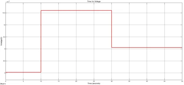
From the above plot, for time interval between 0 to 10 seconds at 293 K temperature, the voltage is 0.008 volts. For the time interval between 10 to 30 seconds at 300 K temperature, the voltage is 0.011 volts. For the time interval between 30 to 50 seconds at 296 K temperature, the voltage is 0.009059 volts.
Once the Threshold voltage 0.009059 is set in the Switch, based on the Constant Value is 1 is passed if temperature is above the 25 degree Celsius (298K) and then DC motor-fan ON(starts) to cool the system otherwise the Constant value 0 is passed to OFF the DC motor-fan. The following the Controlled output Voltage before entering into the Simulink-PS convertor.
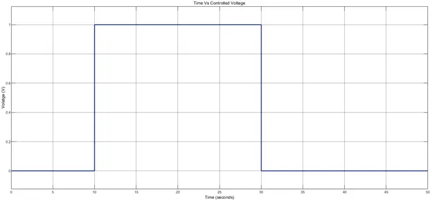
With the help of the Control Voltage Source, the DC Motor is run, and following Velocity and Angular velocity out put plots are generated through the Scopes respectively.
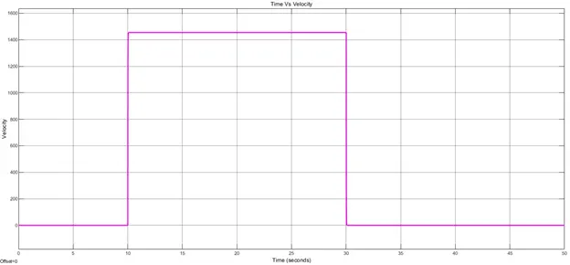
From the above plot, it is observed that the DC motor is ON for time interval between 10 to 30 seconds during which temperature is more than that of 298 K(25 degree Celsius). The below is the plot representing the Angular Displacement of DC-Motor(FAN):
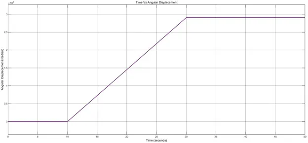
CONCLUSION
The solenoid is used to operate the Doorbell with time delay of 2 seconds and the plunger deflection observed through the Scope generated Position vs Time plot and working principle of solenoid is understood. Furthermore, the DC-Motor(Fan) is operated based on temperature constraints using Thermistor and switch. The operation of DC-motor is observed from the Velocity and Angular Displacement plots and working of NTC thermistor is studied.
References:
- http://crisp.southernct.edu/wp-content/uploads/2016/08/How-Does-a-Doorbell-work.pdf
- https://wonderopolis.org/wonder/how-does-a-doorbell-work
- https://upload.wikimedia.org/wikipedia/commons/9/95/Electric_Bell_animation.gif
- https://www.ck12.org/physics/solenoid/lesson/Electromagnetic-Devices-MS-PS/
- https://www.brighthubengineering.com/consumer-appliances-electronics/43864-how-does-a-door-bell-work/
- https://www.mathworks.com/help/simulink/slref/pulsegenerator.html
- https://www.mathworks.com/help/simulink/slref/scope.html
- https://www.mathworks.com/help/simulink/ug/scope-block-tasks.html
- https://www.mathworks.com/help/simulink/ug/scoped-simulink-function-blocks-in-models.html
- https://www.mathworks.com/help/physmod/simscape/ref/pssimulinkconverter.html
- https://www.mathworks.com/help/simrf/ref/spst.html
- https://www.mathworks.com/help/physmod/sps/ref/battery.html
- https://www.mathworks.com/help/physmod/sps/ref/solenoid.html
- https://www.mathworks.com/help/simulink/ug/displaying-block-outputs.html
- https://www.electrical4u.com/thermistor/
- https://www.omega.com/en-us/resources/thermistor
- https://www.ametherm.com/thermistor/what-is-a-thermistor/
- https://www.littelfuse.com/technical-resources/technical-centers/temperature-sensors/thermistor-info/what-is-a-thermistor.aspx
- https://www.ijert.org/research/simulation-of-thermistor-controlled-fan-using-matlab-IJERTV6IS030474.pdf
- https://ctms.engin.umich.edu/CTMS/index.php?aux=Activities_Lightbulb
- http://www.jetir.org/papers/JETIRA006167.pdf
- http://www.a-lab.ee/edu/sites/default/files/theses/Jevgeni%20Finajev_MSc_thesis.pdf