Week -2
Aim:- 1. A Simulink model of doorbell using solenoid block.
2. To use a thermistor to sense the temperature of a heater and turn on or turn off the fan as per the condition.
1. A Simulink model of doorbell using solenoid block.
Objective:
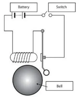
- When the switch is closed the electromagnet receives electric power from the battery and pulls the metal arm to hit the bell producing sound.
Theory:
- In the above arrangement, when the switch is closed the electromagnet receives electrical power from the battery and pulls the metal arm to hit the bell producing the sound. A situation where the switch is closed for 2 seconds and then released. And observe the physical movement of the plunger.
Simulink model of Doorbell:
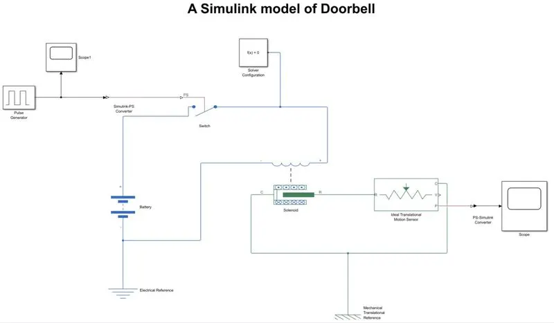
Explanation of Simulink:
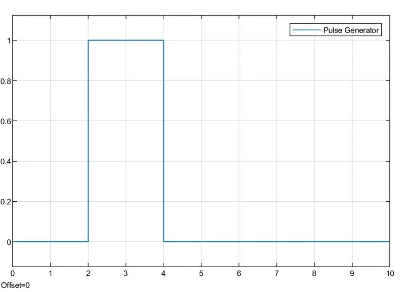
- The command is given by a pulse generator to the circuit. We had connected a scope to display the pulse which was generated by a pulse generator.
- Then we had to use a simulink PS converter to convert the input simulink signal into physical signal.
- Simulink PS converter is now connected to a switch which is opened and shut by pulse which is generated by pulse generator. The power to the circuit is given by the battery.
- The battery end terminal is connected to the electrical references.
- Solver configuration is given to solve configuration equations.
- A Solenoid converts electrical energy into mechanical work. One end of the solenoid converts with a switch and one is connected with electrical reference.
- The other end of the solenoid is connected with an ideal translational motion sensor.
- ideal translational motion sensor a device that converts an across variable measured between two mechanical translational nodes into a control signal proportional to acceleration, velocity, or position.
- And we had connected a mechanical translational reference with solenoid and ideal translational motion sensors.
- After that we had PS Simulink to convert the physical signal into Simulink signal.
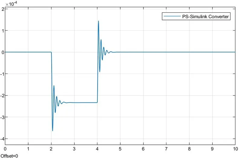
- Here, how we had got the result in the scope, as represented in the graphical form.
Result:
- Solenoid output
- Pulse generated output
2. To use a thermistor to sense the temperature of a heater and turn on or turn off the fan as per the condition.
Objective:
- Use a thermistor to sense the temperature.
- To turn on or turn off the fan as per given temperature coundistion.
Given conditions:
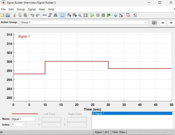
- Temperature source: 20c from 0 to 10 seconds.
- Temperature source: 27c from 10 to 30 seconds.
- Temperature source: 23c from 30 to 50 seconds.
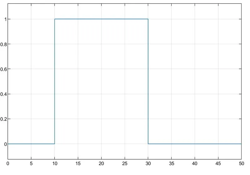
- Fan conditions: a fan should be on if temperature above 25c. and off otherwise.
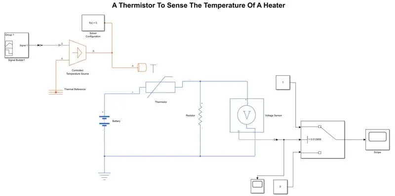
A simulink model of thermistor sensor
Explanation of simulink blocks
- Components:
- Signal builder
- Controlled temperature source
- Thermal reference
- Solver configuration
- Thermistor
- Resistor
- Battery
- Electrical reference
- Voltage sensor
- Constant
- Switch
- Simulink PS converter
- PS simulink converter
- Scope
- Signal builder is used to generate a Groupe signal to a Simulink block. To convert a Simulink PS converter to convert the input Simulink signal into physical signal.
- Then it is connected to a controlled temperature source, an ideal source of thermal energy that is powerful enough to maintain specified temperature difference across the source regardless of the heat flow consumed by the system.
- Other end is connected to a thermal reference.
- A solver configuration is attached to an ongoing circuit line to the thermistor.
- The thermistor therefore heats up, and its resistance decreases thereby increasing the voltage across the PWM reference pins.
- Supply is given by battery to the thermistor and the other end is connected with resistor and voltage as shown in the given figure.
- A voltage sensor is a device that is used to measure the voltage of an electrical circuit or system.
- To convert a physical signal to a Simulink signal we had attached a PS Simulink converter.
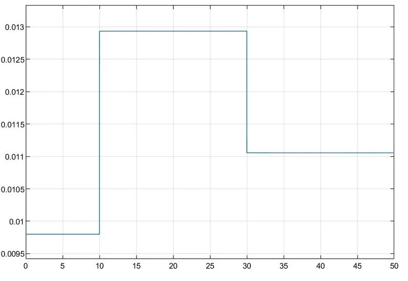
- To set a threshold value we had added a scope before the switch, after getting a maximum value of 27c we had set a threshold at max point to start a fan according to the max temperature.
- The constant value is provided to the switches to match the temperature conditions.
- A result is shown in the scope to show the output plot of the graph of the actual conditions.
Different conditions of time vs temperature
- T1 = 20c = 293.15k – 0 to 10 sec
- T2 = 27c = 300.15k – 10 to 30 sec
- T3 = 23c = 296.15k – 30 to 50 sec
Result:
Conclusion:
- A Threshold value is 0.012559Hz.
- From 0 – 10secound fan is off because the temperature is 20c or 293.15k.
- Which is below 23c or 296.15k, after 10 second it goes to 27c or 300.15k so the fan will turn ON because u2 is greater than the threshold.
- After 30 second fan will turn OFF because the temperature goes down.