Week -2
Aim
To make a simulink model of door bell using solenoid block and to create a situation where the switch is closed for 2 seconds and then released and observe the physical movement of plunger.
Solenoid is an electromagnet with a wire winding and a small metal piston inside it, when electric current flows through the wire, an electromagnetic field is generated which pulls the metal piston towards it ,ie when the switch is closed electromagnet recieves electrical power from the battery and pulls the metal arm to hit the bell producing sound.
Blocks used
- Pulse generator to provide input to the mechanism
- Battery
- Switch which is controlled by external physical signal
- Solenoid block
- Ideal translational motion sensor block to observe the plunger motion
- Scope to obtain the output
- P-S simulink converter as well as simulink p-s converter to convert physical signal to simulink and vice versa
- Electrical and mechanical reference block to provide ground reference
- Solver configuration
Procedure
- Pulse generator generates continuous square pulse and is used to provide physical signal for operating the switch
- Solenoid block and battery block are connected to each other via positive and neqative terminals.
- Switch block placed between battery and solenoid.
- A physical signal through ps port is provided in switch block for the switch to operate .
- Earthing of circuit is provided by connecting to electrical reference.
- C of solenoid block connected to mechanical reference.
- Ideal translation motion sensor sense the position of solenoid to produce output.
- P in the ideal translational sensor represents the position of plunger, here the mechanical process start at R and end at C.
- PS simulink converter convert physical value at port p to simulink value which is connected to scope , where the waveform is obtained.
The values provided to pulse generator are shown in figure1, here the delay seconds is made 2 and a pulse with amplitude 1 for a period of 4 seconds with a pulse width of 50 % is provided as an input to generate the input pulse.
Figure1: Block parameters of Pulse generator
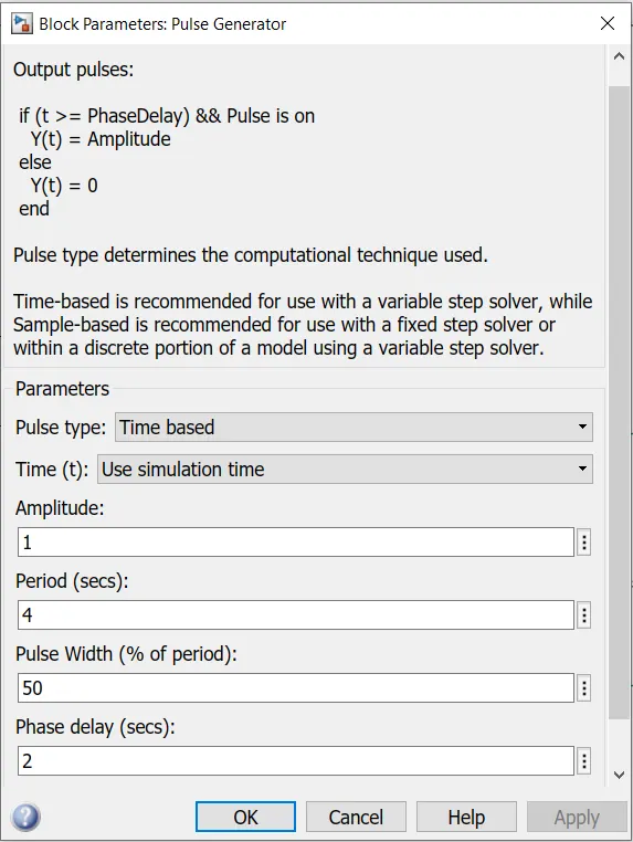
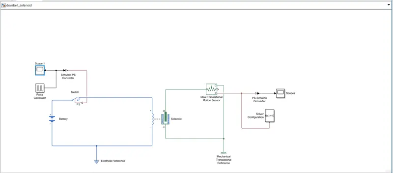
Figure 2 reperesent the simulation of entire system of doorbell using solenoid .
Figure 2: Simulink model of doorbell mechanism using solenoid.
Observations
- From the input waveform obtained we can say that the pulse is generated with a delay of 2 seconds to open and close the switch and theory behind the doorbell mechanism is understood through the challenge.
- From the output waveform obtained one could say that the bell sounds with a delay of 2 seconds.
Waveform results
Figure 3 : Waveform result of the pulse generated at the input ie the waveform of amplitude vs time is obtained at scope1
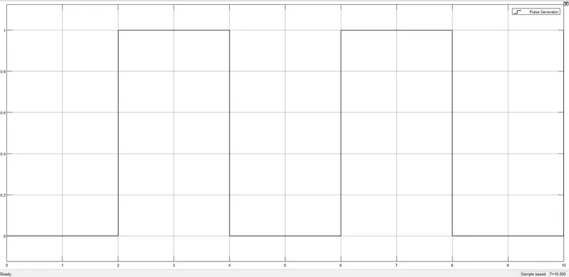
Figure 4 represent the physical movement of plunger, the physical signal is converted via PS simulink converter and the output is obtained at scope 2
Figure 4: Position of plunger vs time

Result
- Simulation of doorbell using solenoid is done and waveforms are obtained.
- Switch is closed for 2 seconds and released , a phase delay of 2 is provided in the pulse generator.
- The input amplitude is observed through pulse generator
- Position of plunger is observed in the scope through ideal translational connected to scopre 2
2)
Aim
To make the simulink model of thermistor to sense the temperature of a heater and turn on and off the fan as per the given conditions
Temperature source:
- 293K from 0-10s
- 300K from 10-30s
- 296K from 30 -50s
Fan condition : ON if the temperature above 298K , OFF otherwise
Thermistor
A type of resistor whose electrical resistance varies with change in temperature. Thermistor act as passive component in circuit.
Blocks used
- Signal builder to provide the input conditions.
- Controlled temperature source maintain a controlled temperature difference regardless of change in temperature rate.
- Thermistor
- Battery
- Electrical and mechanical reference
- Voltage sensor convert the voltage measured between electrical connection to physical signal.
- Physical signal from voltage sensor is converted using PS simulink converter and is provided as an input to the switch.
- Switch, controlled voltage source,scope and display
- DC motor used to analyse the workin of fan.
- Ideal rotational motion sensor, constant and solver configuration.
Procedure
- Input from signal builder is provided to controlled temperature source through a simulink PS converter
- The voltage sensor produces voltage according to the temperature sensed.
- Physical signal from voltage source is converted by ps simulink converter and is supplied to a switch
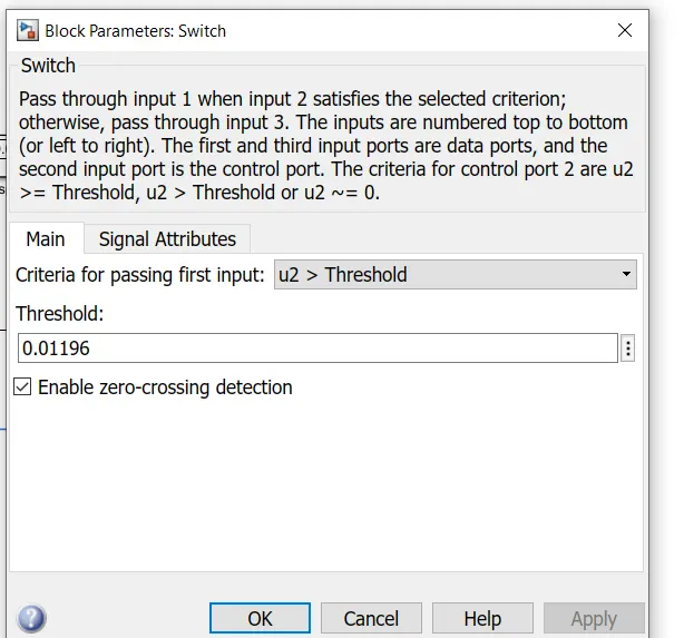
- The switch turns on when the value is above the threshold value inorder to turn on the fan
- When the temperature is above 298K , the fan turn on otherwise is in off condition
- DC motor ids used here inorder to analyse the turning on and off of the fan according to the temperature reference.
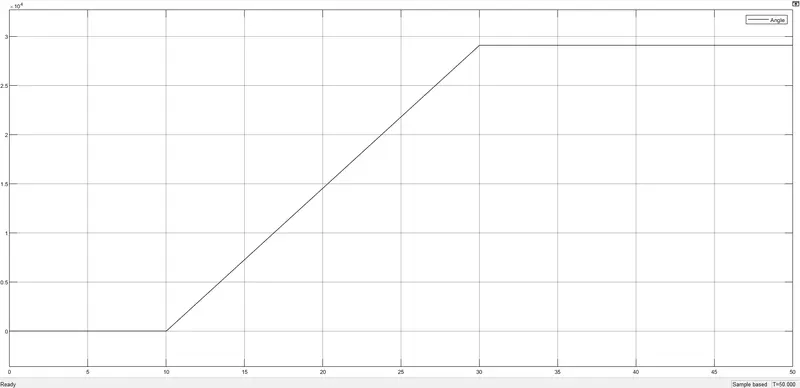
- Ideal rotational motion sensor provides the angular velocity and angle as the output which is displayed after converted by PS simulink converter through scope.
Figure 1 : Input to signal builder according to the temperature conditions
- 293K from 0-10s
- 300K from 10-30s
- 296K from 30 -50s
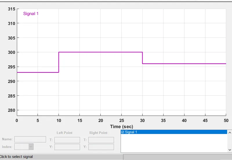
Figure 2: Simulink model of thermistor controlled fan
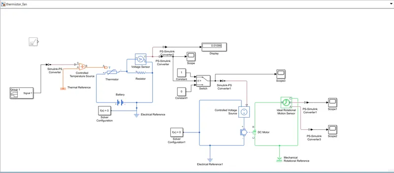
Figure 3: Block parameters of switch , the threshold value of switch is obtained to be 0.01196
Waveform Results and Observations
Figure 4 shows the converterd output from voltage sensor which is supplied to the switch.
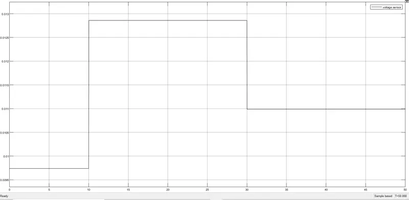
Figure 5 : According to the condition in this case the switch operates for the period 10-30 seconds, where the temperature is 300K which is above 298K and does not operate in the periods 0-10s and 30-50s because the temperature in these case is less than 298k.
Here the fan will turn on when temperature is 300K ie for 10-30s ,otherwise the fan is in off condition when temperature is 293K and 296K. Here the conditon is satisfied.
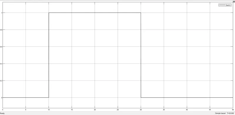
Figure 6: Shows the angular velocity obtained from ideal rotational mechanical sensor.

Figure7: Shows the angle obtained from ideal rotational mechanical sensor
Result
- Simulation of thermistor to sense the temperature of a heater and turn on and off the fan as per the given conditions is done.
Temperature source:
- 293K from 0-10s
- 300K from 10-30s
- 296K from 30 -50s
- The temperature of heater is sensed and from the waveform obtained we can say that the switch operates when the temperature is above 298K and causing the turn on of the fan.