Week -2
Aim:
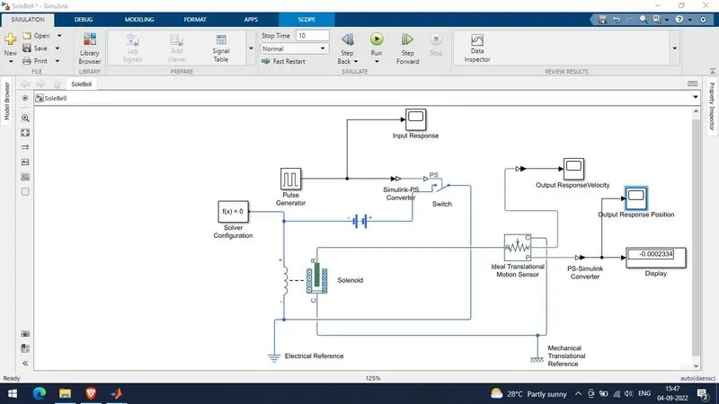
To Make a Simulink model of Doorbell using solenoid block using given conditions:
- Bell 2 second On.
- Bell 2 Second Off.
Apparatus:
- Solenoid.
- Pulse Generator.
- Switch.
- Battery.
- Solver Configuration.
- Ideal Translational Motion Sensor.
- Mechanical Translational reference.
- Electrical Reference.
- Scope.
Model Diagram:
Theory:
An elecrical conductor when wound in the from of a helix is called a Solenoid and when a current of electricity is passed through the turns of wire it possesses many of the characteristics of permanent bar magnet.
Working:
- We use a pulse generator block to give a pulse signal of 2 minutes on and 2 minutes off characteristic for total duration of 10 seconds.
- The generated pulse is fed to a switch through a Simulink-PS converter which converts Simulink signal to a physical signal.
- The switch controls the battery supply to the solenoid based on the ON-OFF pulse provided to it.
- An electrical reference is connected to the electrical circuitory which acts as ground to entire electrical sectioin.
- The Ideal Translational motion sensor is used to sense the movement of the plunger. The Plunger motion is a physical signal, Hence we use a PS - Simulink converter to get the ouputs in the scope. The physical motion is sensed by connecting R & C port of Solenoid to the R & C ports of Ideal Translationnal Motion Sensor.
- We are also using a Mechanical translational Reference that acts as a ground to the mechanical system.
Results & Conclusion:
- By observing position and velocity response through the scope we get to know that the Solenoid based bell is working as per the condition given in the question i.e., 2 Seconds ON & 2 seconds OFF with a settling time of 0.5 seconds for position as well as velocity of the plunger.
- Hence we have designed a doorbell using a Solenoid based system.
Aim:
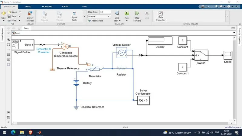
use a thermistor to sense the temperature of a heater & turn on or turn off the fan as per the given conditions:
=> t0 to t10 - 20° C or 293° K.
=> t10 to t30 - 27° C or 300° K.
=> t30 to t50 - 23° C or 296° K.
Apparatus:
- Signal Builder.
- Controlled Temperature source.
- Thermistor.
- Battery.
- Resistor.
- Voltage Sensor.
- Electrical Reference.
- Thermal Reference.
- Solver Configuration.
- Switch.
- Constants.
- Scope.
- Display.
Model Diagram:
Theory
Thermistors are thermally sensitive semiconductors resistors which show a decrease in resistance as temperature increases.
Working
- We have used a signal builder block to simulate the provided temperature conditions
=> t0 to t10 - 20° C or 293° K.
=> t10 to t30 - 27° C or 300° K.
=> t30 to t50 - 23° C or 296° K.
- The signal builder block output is fed to the controlled temperature sensor through a Simulink - PS converterwhich helps in maintaining a specific temperature.
- This controlled temperaure is exposed to the thermistor.
- The thermistor is connected to a resistor in series to which a voltage sensor is connected across this voltage sensor is the deciding point where the switch gets to know the threshold voltage using which the switch can be turned On or OFF.
- A 12 V battery is connected to drive the circuit.
- Solver Configuration bock is connected to this circuitory.
- The voltage sensor feedback is fed to the switch through PS - Simulink converter this helps to decide whether to switch On or Switch Off. The same response is displayed in the Scope.
Results & Conclusion:
- By observing the switch output through scope we understand that the thermistor based temperture sensitive switch outputs are as per the given conditions i.e.,
=> t0 to t10 - 20° C or 293° K.
=> t10 to t30 - 27° C or 300° K.
=> t30 to t50 - 23° C or 296° K.
- The switch remains OFF till the temperature reach 27° C or 300° K.
- It switch turns ON at t10 second till t30 second because temperature during this duration is 27° C or 300° K.
- The switch turns OFF at t30 till t50 second because the tempertaure during this duration is 23° C or 296° K.
- Hence we have designed a temperature controlled switch for a Fan using a thermistor.