Project
Aim:
To study, analyze the working of Baha All-Terrain-Vehicle (ATV) model using simulink, understanding the working of the same in two different models(with Dashboard, without dashboard) and preparing a detailed report expalining the model blocks and using two approaches.
Blocks Used:
- Signal Builder
- Generic Engine
- RPM Sensor
- Ideal Rotational Motion Sensors
- Variable Ratio Gear
- Simple Gear
- Wheels
- Double Shoe Break
- Vehicle Body/Chassis
- Break
- Integrator
- Scope
- Circular Gauge
- Knob
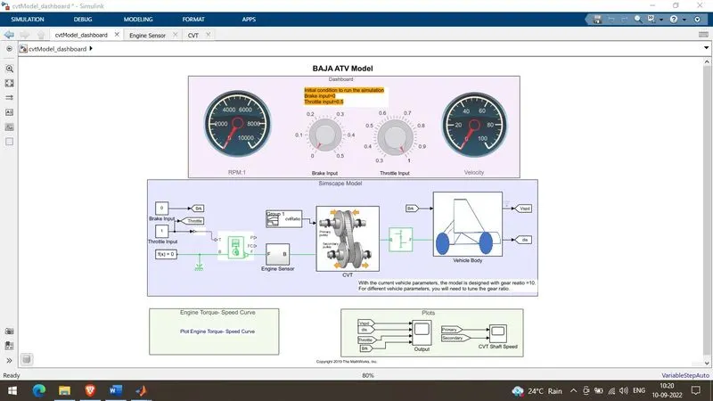
Model Diagram(With Dashboard):
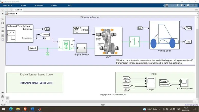
Model Diagram(Without Dashboard):
Theory:
- Baja is an all-terrain-vehicle design competetion which gives students an opportunity to design and develop their own all terrain vehicle. As the name itself suggest all terrain vehicle it is a robust vehicle which can run on any terrain such as soil, gravel, pebbels, mud, sand. We will be studying Baja All Terrain Vehicle (ATV) Model Provided in the question.
Working:
- The main input blocks are Brake input and Throttle input. These inputs are fed to the Generic Engine & Double Shoe Brake respectively. The Double Shoe Brake is connected to the rear wheels of the vehicle. The Break Input is connected to the Double Shoe Brake via a Gain block with a gain of 1000. Gain block helps amplify the brake pedal pressure as per the reqirement at the Double Shoe Brake and response time.
- We have two approaches here to feed the Brake input and Throttle input - first approach is through the Signal Builder Block and the second approach is through Knob Block of the dashboard.
- Main difference between these two approach is the type of input being fed. In first approach the input fed is predefined and cannnot be changed at the run time, whereas in the second case the inputs can be changed during runtime or dynamically and gives us realtime outputs simultaneously.
- As the Generic Engine is fed with Throttle Input the corresponding output is taken through the Engine Crank Shaft rotation(F). The crank shaft transmits power generated from the combustion inside the engine.
- Inorder to measure the generated power by the engine in the form of RPM, we use a RPM sensor to calculate and plot and the same is fed to the Continuously Variable Transmission(CVT) block along with scope and Circular Gauge to display it on Dashboard in case of Dasboard based model.
- Continuously Variable Transmission (CVT) based system doesn't use gears unlike any conventional transmission system instead it uses two shafts which are namely driver shaft (connected to engine) and driven shaft(connected to the wheels or axle). Both the shafts are designed using pulleys whose one side is movable and other side is fixed. As these movable sides of pulley moves the dia of shaft increases and decreases proportionately. This phenomena helps avoid gears and makes the system gearless. Instead of moving between the gears the dia changes corresponding to the gear ratio.
- Gear ratio is given as (Input speed)/(Output speed).
- The Engine Crank Shaft output is connected to the Variable Ratio Gear block input which is the Base drive shaft and the gear ratio which is fed using Signal builder block is also connected to the Variable Ratio Gear. These are all the sub blocks of Continuously Variable Transmission (CVT).
- The Continuously Variable Transmission (CVTs) output (F) Follower Pulley is fed to the input Base Pulley (B) of the Simple Gear Block and the Simple Gear Block output is fed to the rear wheels reverse axle ports.
- The reason for using the Simple Gear Block is for tuning the output which come from the Generic Engine through Continuously Variable Transmission (CVT) and sending it to the axle of the rear wheel drive All Terrain Vehicle(ATV).
- The Vehicle Body/Chassis are fed wih Normal reaction from the rear & front wheels, all four wheels are connected to the chassis using the Hub.
- The front wheels are not connected to the axle as it is rear wheel drive.
- Wind velocity and inclination angles are fed to the Vehicle body respectively.
- Vehicle velocity is fed to scope and also connected to Circular gauge to display on the Dashboard in case of dashboard based models.
- In these two models we are monitoring 7 parameters through scope and plot which are:
1. Torque - Speed Curve
2. Vehicle Speed.
3. Throttle.
4. Brake.
5. Primar CVT shaft speed.
6. Secondary CVT shaft speed.
Response using Model without Dashboard.
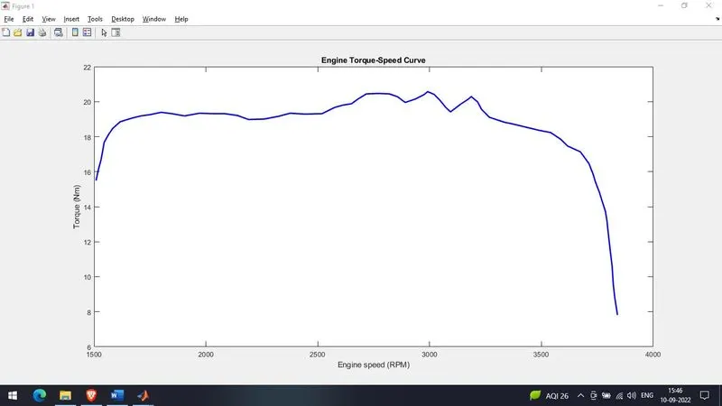
Fig: Engine Torque - Speed Curve
- The Speed, Torque values are fed from the MATLAB workspace window to the Generic Engine block to generate the output RPM accordingly. This plot behavior is generic to all Internal Combustion Engines(ICE).
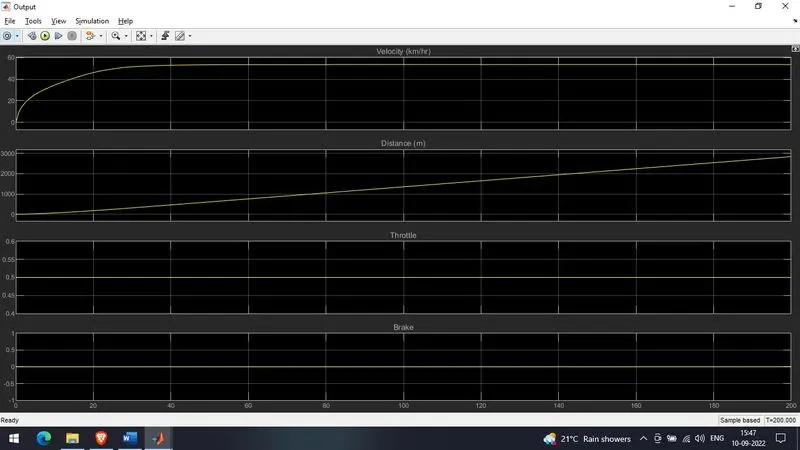
Fig: Velocity, Distance, Throttle & Brake Response Plots.
- Here we can observe from the plot that Brake Value = 0 & Throttle Value = 0.5 are constant through out the simulation.
- It is also noticed that there is a rapid increase in the velocity of the vehicle initially later it stabilizes as the engine reaches its constant RPM.
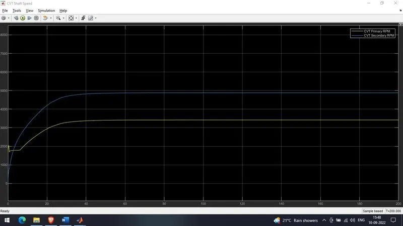
Fig: CVT Primary and Secondary Pulley RPM
- Here we can observe that the CVT Primary RPM looks similar to the Engine RPM as its diretly connected to the Generic Engine.
- It looks similar but the RPM values may vary as there are other factors contributing to it such as Inertia and it will have some losses with degradation in the RPM values.
Response using Model with Dashboard.
Case I: (Throttle -> 0.5; Brake-> 0)
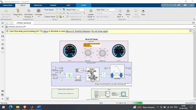
Fig: Model with Brake 0 & Throttle 0.5
- In this case we are keeping the Brake Value = 0 & Throttle Value = 0.5 constant throughout simulation, similar to the one without dashboard.
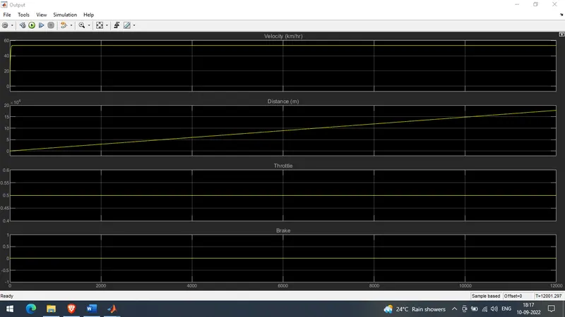
Fig: Velocity, Distance, Throttle & Brake Response Plots.
- Here we can observe from the plot that Brake Value = 0 & Throttle Value = 0.5 are constant through out the simulation.
- It is also noticed that there is a rapid increase in the velocity of the vehicle initially later it stabilizes as the engine reaches its constant RPM.
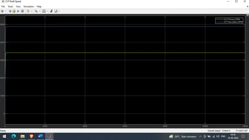
Fig: CVT Primary and Secondary Pulley RPM
- Here we can observe that the CVT Primary RPM looks similar to the Engine RPM as its diretly connected to the Generic Engine.
- It looks similar but the RPM values may vary as there are other factors contributing to it such as Inertia and it will have some losses with degradation in the RPM values.
Case II: (Throttle -> 0.5; Brake-> Varying)
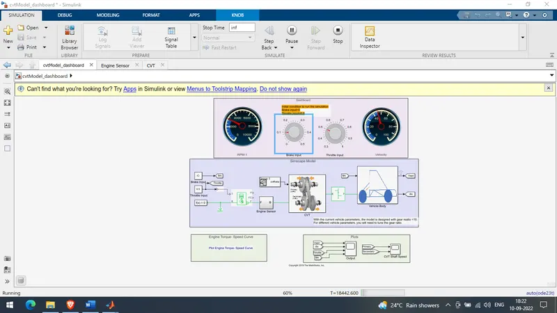
Fig: Model with Brake Varying & Throttle 0.5
- In this case we keep Throttle Value = 0.5 & Brake Value = varying throughout the simulation and observe the response in the scope..
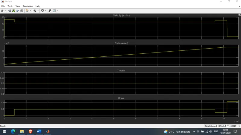
Fig: Velocity, Distance, Throttle & Brake Response Plots.
- Here in this case it is clearly seen that throttle remains constant throughout the simulation.
- As there is variation in braking we can find the changes reflected in the velocity of the vehicle and finally there comes a point when the vehicle velocity touches zero.
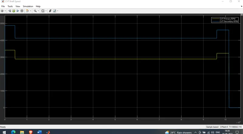
Fig: CVT Primary and Secondary Pulley RPM
- As there is continuous change in the braking pattern the CVT also tries to align itself according to the velocity of the vehicle as per the gear ration provided by default.
- Drop in both Primary and Secondary Shaft RPMs is observed & as the vehicle comes to stop relatively the CVT shaft RPm also comes down to zero.
Case III: (Throttle -> Varying; Brake-> 0)
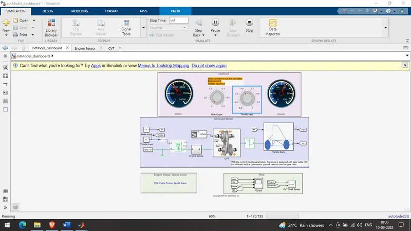
Fig: Model with Brake 0 & Throttle Varying
- In this case we are keeping the Brake Value = 0 & Varying the throttle Values, also we are observing the corresponding Vehicle Velocity, Throttle, Distance, Brake and Primary/Secondary Shaft RPM of CVT.
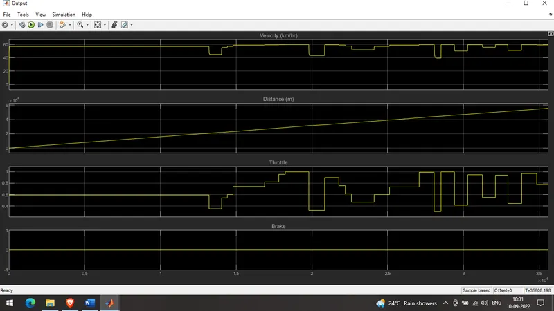
Fig: Velocity, Distance, Throttle & Brake Response Plots.
- As we can clearly see from the plot that the Brake value throughout the simulation is zero, throttle value is changed aggressively and corresponding changes are also observed in the velocity of the vehicle.
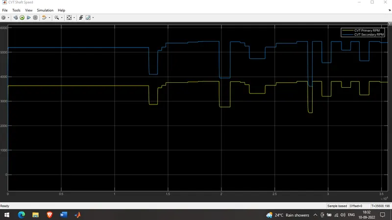
Fig: CVT Primary and Secondary Pulley RPM
- Here the result of aggressive acceleration and deceleration is noticed in the CVT shaft outputs the change in primary pulley and secondary pulley is clearly observed. As the primary pulley of the CVT is dirctly connected to the Generic Engine so each and every change in the Throttle value is directly reflected in the CVT.
- In these models instead of signal builder block for CVT ratio a Look up table is used.
Models with Lookup Tables:
- We also have models with lookup tables which help us simulate using the predefined values from previous studies or from the research values of currently available vehicles where as the dynamic system based models helps us simuate the values of our own interest and findout the corresponding results. Lookup tables may have some limitations
Conclusion & Result:
- The major differences between the Model with dashboard and without dashboard are:
- The model with dashboard allows us to change the inputs which are throttle and brake dynamically during runtime and gives us a realtime output based on the dynamic inputs, where as in case of model without dashboard the values will be predefined and outputs will be limited to the fed inputs and inputs cannot be varied during runtime.
- Both models have their own benefits like using dashboard we may find out a specific value of both inputs in which the behaviour might be not conventional or as per the expected output in that case we can use model without dashboard and feed the specific set of values found out using the dashboard model and give those models using Signal Generator blocks to carryout indepth analysis of the same.
- As of now the sytem seems to be an open loop system in terms of gear ratio and speed which are actually pre defined using lookup table. We can give the vehicle speed as feedback to the CVT and a controller to define CVT ratio based on the vehicle speed will be more realistic and dynamic and it will be more adaptive will act as closed loop system.
- Hence, A technical report after studying and analyzing the working of Baha All-Terrain-Vehicle (ATV) model using simulink for two different models(with Dashboard, without dashboard) is made.