Project 1 - Controlling a DC motor using PWM and monitoring its Running status
Aim:
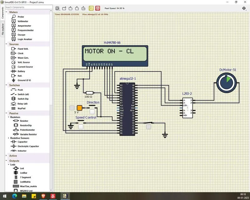
Implement a system on the simulator for controlling a DC motor using L293 motor driver, monitor its status and print the running status of motor on the LCD Display.
Circuit:
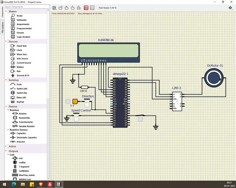
Code:
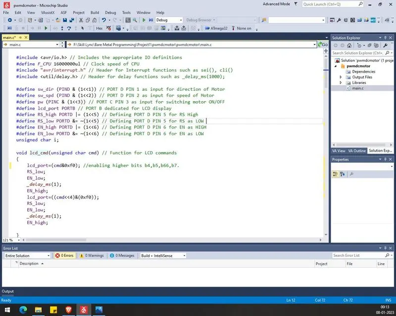
#include <avr/io.h> // Includes the appropriate IO definitions
#define F_CPU 16000000ul // Clock speed of CPU
#include "avr/interrupt.h" // Header for Interrupt functions such as sei(), cli()
#include <util/delay.h> // Header for delay functions such as _delay_ms(1000); #define sw_dir (PIND & (1<<1)) // PORT D PIN 1 as input for direction of Motor
#define sw_spd (PIND & (1<<2)) // PORT D PIN 2 as input for speed of Motor
#define pw (PINC & (1<<3)) // PORT C PIN 3 as input for switching motor ON/OFF
#define lcd_port PORTB // PORT B dedicated for LCD display
#define RS_high PORTD |= (1<<5) // Defining PORT D PIN 5 for RS High
#define RS_low PORTD &= ~(1<<5) // Defining PORT D PIN 5 for RS as LOW
#define EN_high PORTD |= (1<<6) // Defining PORT D PIN 6 for EN as HIGH
#define EN_low PORTD &= ~(1<<6) // Defining PORT D PIN 6 for EN as LOW
unsigned char i;
void lcd_cmd(unsigned char cmd) // Function for LCD commands
{
lcd_port=(cmd&0xf0); //enabling higher bits b4,b5,b66,b7. RS_low; EN_low; _delay_ms(1); EN_high; lcd_port=((cmd<<4)&(0xf0)); RS_low; EN_low; _delay_ms(1); EN_high; }
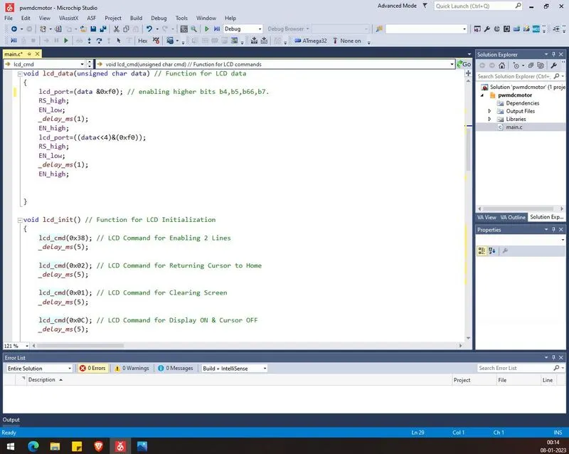
void lcd_data(unsigned char data) // Function for LCD data
{
lcd_port=(data &0xf0); // enabling higher bits b4,b5,b66,b7. RS_high; EN_low; _delay_ms(1); EN_high; lcd_port=((data<<4)&(0xf0)); RS_high; EN_low; _delay_ms(1); EN_high; }
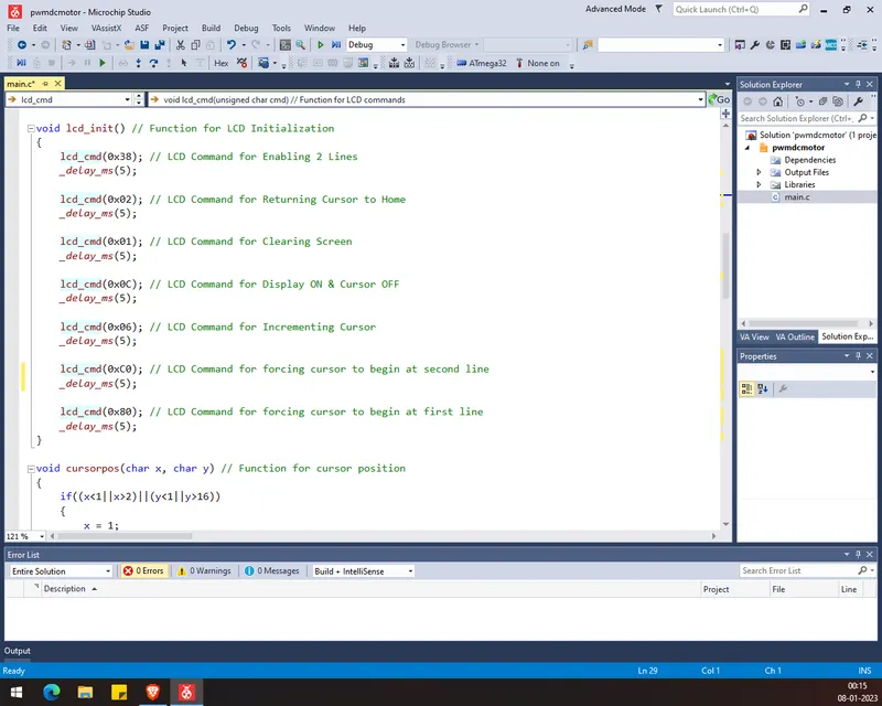
void lcd_init() // Function for LCD Initialization
{
lcd_cmd(0x38); // LCD Command for Enabling 2 Lines
_delay_ms(5);
lcd_cmd(0x02); // LCD Command for Returning Cursor to Home
_delay_ms(5);
lcd_cmd(0x01); // LCD Command for Clearing Screen
_delay_ms(5);
lcd_cmd(0x0C); // LCD Command for Display ON & Cursor OFF
_delay_ms(5);
lcd_cmd(0x06); // LCD Command for Incrementing Cursor
_delay_ms(5);
lcd_cmd(0xC0); // LCD Command for forcing cursor to begin at second line
_delay_ms(5);
lcd_cmd(0x80); // LCD Command for forcing cursor to begin at first line
_delay_ms(5);
}
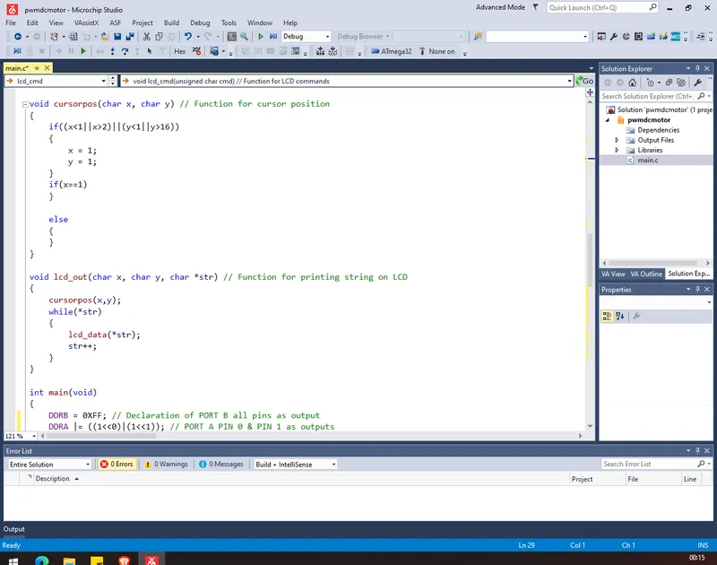
void cursorpos(char x, char y) // Function for cursor position
{
if((x<1||x>2)||(y<1||y>16))
{
x = 1;
y = 1;
}
if(x==1) { lcd_cmd(0x7F+y);
}
else
{ lcd_cmd(0xBF+y);
}
}
void lcd_out(char x, char y, char *str) // Function for printing string on LCD
{
cursorpos(x,y);
while(*str)
{
lcd_data(*str);
str++;
}
}
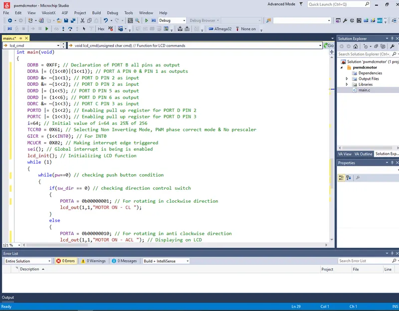
int main(void)
{
DDRB = 0XFF; // Declaration of PORT B all pins as output
DDRA |= ((1<<0)|(1<<1)); // PORT A PIN 0 & PIN 1 as outputs
DDRD &= ~(1<<1); // PORT D PIN 2 as input
DDRD &= ~(1<<2); // PORT D PIN 2 as input
DDRD |= (1<<5); // PORT D PIN 5 as output
DDRD |= (1<<6); // PORT D PIN 6 as output
DDRC &= ~(1<<3); // PORT C PIN 3 as input
PORTD |= (1<<2); // Enabling pull up register for PORT D PIN 2
PORTC |= (1<<3); // Enabling pull up register for PORT D PIN 3
i=64; // Initial value of i=64 as 25% of 256
TCCR0 = 0X61; // Selecting Non Inverting Mode, PWM phase correct mode & No prescaler
GICR = (1<<INT0); // For INT0
MCUCR = 0X02; // Making interrupt edge triggered
sei(); // Global interrupt is being is enabled
lcd_init(); // Initializing LCD function
while (1)
{
while(pw==0) // checking push button condition
{
if(sw_dir == 0) // checking direction control switch
{
PORTA = 0b00000001; // For rotating in clockwise direction
lcd_out(1,1,"MOTOR ON - CL ");
}
else
{
PORTA = 0b00000010; // For rotating in anti clockwise direction
lcd_out(1,1,"MOTOR ON - ACL "); // Displaying on LCD
}
OCR0 = i; // increasing i in ISR so corresponding value is being loaded into OCR0
}
PORTA = 0x00; // For stopping rotation
lcd_out(1,1,"MOTOR OFF"); // Displaying on LCD
}
}
ISR(INT0_vect) // Interrupt Service Routine
{
i = i+20; // increasing i value results in increasing PWM
}
Code Screenshot:
Output: